 Xinyan Wang1*
 Yichao Li2
- 1School of Automotive Engineering, Tianjin Vocational Institute, Tianjin, China
- 2Tianjin Yantuo Technology Co., LTD., Tianjin, China
Introduction: The rapid development of electric vehicle technology in the field of renewable energy has brought significant challenges to wireless charging systems. The efficiency of these systems is crucial for improving availability and sustainability. The main focus of the research is to develop an intelligent charging strategy that utilizes fuzzy logic to optimize the efficiency of wireless charging systems for electric vehicles.
Method: Introduce a model that combines fuzzy logic algorithm with automatic control system to improve the wireless charging process of electric vehicles. The model adopts dynamic tracking and adaptive control methods by analyzing the characteristics of static wireless charging systems. Utilizing primary phase shift control and secondary controllable rectifier regulation, combined with optimized fuzzy control algorithm.
Result and discussion: The experimental results show that when the secondary coil is stable, the model maintains a stable duty cycle of about 75.6% and a stable current of 5A. It was observed that when the mutual inductance values were set to 10, 15, and 20 uH, the efficiency of the primary coil before applying control decreased with increasing resistance.
Conclusion: The proposed system has shown great potential for application in real-world electric vehicle charging systems, demonstrating good applicability and feasibility in controlling the charging process and tracking the optimal efficiency point. The integration of fuzzy logic enhances the system’s ability to adapt to different operating conditions, which may lead to wider implementation and improved operational efficiency.
1 Introduction
New energy vehicles have become a more widely used new type of vehicle. At the same time, electric vehicles have become the main target for promoting new energy vehicles due to their mature technology and better maintenance efficiency (Aatabe et al., 2021). One of the core technologies for electric vehicles is the high-efficiency Permanent Magnet Motors (PMMs), of which reduced rare earth PMMs are gradually becoming the mainstream choice for electric vehicle power systems due to their high energy efficiency, small size, light weight and high torque density. With the increasing performance requirements of new energy vehicles, reduced rare earth PM motors need to pay more attention to cost reduction, material substitution and sustainable development while maintaining high efficiency. The stable supply, cost, and environmental impact of rare earth materials are the main issues that the current electric vehicle industry needs to face. As one of the world’s largest electric vehicle markets, China’s rapid development in battery technology and electric vehicle manufacturing has not only led the global market, but also made remarkable achievements in technical architecture and technological breakthroughs. The rapid rise of China’s electric vehicle industry is attributed to its strong manufacturing foundation, huge market demand, and active policy support from the government. Especially in terms of battery technology, electric vehicle batteries made in China have occupied an important position in the international market due to their high energy density, long life and low cost. In recent years, the promotion of electric vehicles has become an important initiative for the development of new energy vehicles in the country, but the performance and safety of the car has also become an important issue affecting promotion (Xu et al., 2021). Wireless energy transmission technology is the core technology of wireless charging for electric vehicles, which has been applied in many fields (Nasab et al., 2023). Although most electric vehicles still rely on wired charging, the loss of charging efficiency and the inconvenience of frequent unplugging operations are still important factors limiting its widespread promotion (Nasab et al., 2024). Therefore, how to optimize the charging control process of electric vehicles, as well as how to determine the optimal charging efficiency point, is a key problem to be solved (Ahin, 2020). Meanwhile, the current wireless charging technology for electric vehicles mainly focuses on several aspects such as efficiency optimization, maximum power transmission, and dynamic charging (Mirza et al., 2021a). In addition, due to the air gap in the original and secondary coupling mechanisms, it is difficult to align the original and secondary coils when stopping, which will affect the power and efficiency of the system. Among them, the transmission efficiency of the system is one of the key issues in promoting the wireless charging system for electric vehicles. Based on this, an optimized scheme for the wireless charging system of electric vehicles is proposed, which can automatically control the charging process and accurately confirm the optimal efficiency point of charging. The new approach designs a completely new system and uses a fuzzy control algorithm to enhance the system performance. This not only focuses on improving charging efficiency, but also aims to simplify the system circuit design and reduce heat generation during operation to reduce costs and improve the overall reliability of the system. It is expected to provide a more efficient and reliable solution for wireless charging technology of electric vehicles. This study consists of four parts. The first part provides a brief overview. The second part is to design the system scheme and build a system model. The third part verifies the feasibility of the system through experiments. The fourth part summarizes the entire study.
2 Related works
Fuzzy logic algorithms not only perform well in the automotive industry, but are also widely used in other industries. Optimal efficiency tracking is an important application of this algorithm. Badoud et al. found in their research on solar photovoltaic systems that traditional algorithms couldn't track the optimal power in the system. Therefore, a new fuzzy logic algorithm controller was proposed to track and control the system. The new controller could track and find the optimal efficiency point in the system. The experimental results showed that the stability and robustness of the new algorithm controller were much higher than those of traditional algorithm controllers (Badoud et al., 2021). Bhukya and Nandiraju found that traditional algorithms couldn't fully track the optimal power point due to the randomness and intermittency of photovoltaic systems. Therefore, an optimization algorithm model based on fuzzy logic algorithm was proposed, which used the grasshopper optimization algorithm as the membership function. The experimental results showed that the new algorithm model could track and optimize the optimal power. The efficiency far exceeded that of traditional algorithms (Bhukya and Nandiraju, 2020). Currently, electric vehicles are developing rapidly. However, the field is facing various problems. Vanitha et al. believed that achieving automatic charging control for electric vehicles was a challenge. Therefore, an intelligent charging system based on the deep learning and machine learning was proposed. The system could intelligently identify the number of charging ports in the charging station, reducing the waiting time for charging. The experimental results showed that this algorithm for intelligent recognition could shorten the charging time of electric vehicles and control the vehicle more efficiently (Vanitha et al., 2020). Han et al. believed that there were many uncertainties when charging electric vehicles. Therefore, a link prediction model was proposed to control the charging status of electric vehicles at various stages. The new model could predict the cars in different parking lots at different time periods, calculate the charging station load, and control car charging. The experimental results showed that the predicted car charging state could be well controlled, verifying the feasibility of the model (Han et al., 2020).
El-Samahy et al. analyzed the charging state of electric vehicles. Fuzzy logic was used to control deviation signals. The algorithm was used to improve the frequency stability of the electric vehicle power grid. The experimental results showed that the fuzzy logic controller could automatically control the charging status of electric vehicles (El-Samahy et al., 2020). Kumar and Sharma believed that electric vehicles could participate in various fields related to renewable energy. The development and application of predictive controllers were applied in reality. Therefore, an MPC-HHO algorithm based on electric vehicles was proposed. This algorithm could predict the frequency and oscillation of electric vehicles. The experimental results indicated that the algorithm was feasible and effective for predicting electric vehicles (Kumar and Sharma, 2021). Zhang et al. believed that electric vehicles generated enormous speed and torque when driven by electric motors. This was extremely difficult for electric vehicle control. Therefore, a model coupled transmission based on particle swarm optimization algorithm was proposed for synchronous control. The experimental results indicated that the new transmission could eliminate the impact of the synchronizer on vehicle speed and torque, and improve the control ability of electric vehicles (Zhang L. et al., 2020a).
In summary, the research in the field of electric vehicles is currently in the basic experimental research stage. Many studies still cannot achieve automatic control during the charging stage of electric vehicles. At the same time, the research on the optimal efficiency point of electric vehicles is not yet perfect. Therefore, the study will focus on the optimal efficiency points of electric vehicles and integrate fuzzy algorithms to achieve automatic charging control for electric vehicles.
3 Optimal efficiency point membership and electric vehicle charging stage control integrating fuzzy logic
This chapter mainly designs the charging control system of electric vehicles that incorporates fuzzy logic. Firstly, the design scheme is explored to achieve the optimal efficiency of the system control scheme. Then, the charging stage of the electric vehicle is analyzed to establish an automatic control system for the charging stage.
3.1 Design of optimal efficiency point system control scheme for electric vehicles
Wireless Power Transfer (WPT) technology for electric vehicles is currently the core of wireless charging for electric vehicles. The MC-WPT system is the main system device of this technology (Wang et al., 2021a; Li et al., 2021). To improve the efficiency of the MC-WPT system and achieve the optimal efficiency point of the vehicle, different power topologies and control methods in electric vehicles are analyzed. In practical applications, the leakage inductance of the electromagnetic circuit in the MC-WPT system is too large, resulting in a lot of reactive power. Therefore, if the coil is not subjected to resonance compensation, it will result in a decrease in efficiency and not meet the requirements for use. There are currently three main types of resonant compensation for MC-WPT systems, namely, SS type, LCL-S type, and LCL-LCL type. The secondary edge reflection impedance of SS topology is shown in Eq. 1 (Kavya and Jayalalitha, 2021).
In Eq. 1,
In Eq. 2,
The parameters in Eq. 3 are consistent with the above parameters.
All parameters in Eq. 4 are consistent with the above parameters.
In Eq. 5, to ensure that the parameters can be reasonably configured for the coupled structure, the capacitance and inductance of the original side are resonated, so that the resonance frequency is the same.
In Eq. 6, the value representation of the parameters is the same as the above equation. The LCC-LCC resonant topology composition structure is consistent with the LCC-S type, but the expressions of capacitance and inductance are different. All three different topologies have advantages and disadvantages. The topology coil current of LCC-S and LCC-LCC types is stable, which are independent of the circuit load. However, the circuit structure is relatively complex. The number of resonant stages and harmonic frequency will increase the impact. This makes it difficult to design the system, while increasing the consumption of the system (Yang, 2022; Zhang X. et al., 2023a). In the wireless charging system for electric vehicles, the parking of electric vehicles is affected by the coupling structure, resulting in changes in the parking position. Therefore, composite resonance will make the structure of the tram more complex.
Frequency is independent of load in the SS type structural system. The power and efficiency of trams are higher, and the established model is simpler. Therefore, in the optimization design of the tram system, SS type resonance is usually used for system construction. The structural framework of the electric vehicle coupling structure system constructed by the SS type resonant topology is shown in Figure 1.
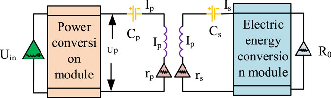
Figure 1. Schematic diagram of tram coupling structure.
The topology of the tram MC-WPT system in Figure 1 consists of two modules, the power change module and the electrical energy conversion module. The ratio of system output to input power at this time is shown in Eq. 7.
In Eq. 7,
In Eq. 8, the parameters are consistent with the above parameters. The total efficiency is used to calculate the optimal efficiency point of the load for the secondary resistance, as shown in Eq. 9 (Shao et al., 2023).
In Eq. 9, parameter calculation can achieve the lowest efficiency value by changing the impedance of the secondary side. It is also a commonly used optimal efficiency point tracking method in the system. In the MC-WPT system, both output and input efficiency are determined by the efficiency of the primary and secondary edges. Therefore, in the design of the system, the maximum system efficiency can be achieved by changing the equivalent efficiency or resistance of the secondary or primary edges. The optimal efficiency point of electric vehicles is achieved through changes in electrical energy and power, as well as mutual cooperation. The primary edge in the system cannot protect the system through current and voltage information. Therefore, information mutual inductance is applied to the primary and secondary edges (Zhang et al., 2021; Yang et al., 2024; Zhao et al., 2024).
According to the efficiency analysis of system best practices, there are two best practices. One method is direct control, which changes the impedance of the secondary side by changing the electrical energy to achieve the optimal impedance and load. The transmitted data is changed to receive the secondary voltage on the primary side, thereby achieving target control.
Another method is to indirectly control the electrical energy system. When the system parameters have been determined, the electrical energy conversion device of the secondary side is controlled. The primary side receives the current from the secondary side for system control. For electric vehicles, the parking position affects the coefficient of system coupling. Therefore, the selected impedance value cannot be directly calculated (Lyu et al., 2024). Therefore, the observation method is used for calculation to ensure the actual value of the original edge by controlling the impedance value of the secondary edge. Then the wireless signal is input to calculate the impedance of the secondary side. The comparison of system control methods is shown in Table 1.
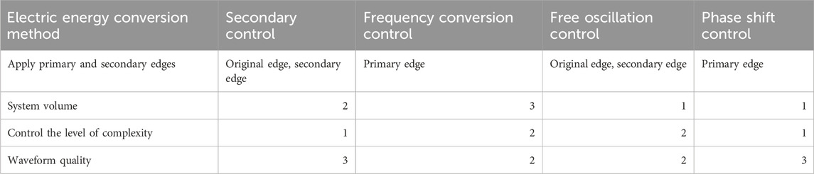
Table 1. Comparison of system control methods.
In Table 1, different power control methods have different system edges, resulting in different waveforms and data. If the level in the table is high, the system parameters will be better at this time. The battery in the tram system will generate impedance to the charging state parameters of the tram. Therefore, using direct tracking methods directly is not suitable for system data. When the conduction ratio of the secondary side switch is
In Eq. 10,
In Eq. 11,
In Eq. 12, the parameter expression is consistent with the above parameter equation expression. After ignoring the loss of system switches, the result is as shown in Eq. 13 (Shen et al., 2024).
In Eq. 13,
3.2 Optimal efficiency point membership based on fuzzy logic and system construction for various charging stages of electric vehicles
Fuzzy control algorithm is currently the main method used to solve nonlinear surface and control problems. The simple operation process and strong aluminum rod performance make it the optimal algorithm for the current electric vehicle optimal efficiency point confirmation system. The basic algorithm flow is shown in Figure 2.

Figure 2. The basic algorithm process of electric vehicles.
In Figure 2, firstly, the fixed value and the input variable deviation of the fuzzy controller are inputted. The input parameters include desired speed, temperature, or other parameters that need to be maintained by the electric vehicle system, etc., which are inputted into the fuzzy controller before executing the algorithm’s mechanism composition. The controller receives the input data, including error or deviation from the desired value. Finally, the mechanism composition of the algorithm is fed into the controlled object. The final output is the value u of the controlled variables, some of which are reintroduced into the initial state of the system by the sensors. Sensors measure the actual performance of controlled objects and provide feedback to the controller, thereby creating a feedback loop. Variable judgment is determined by the controlled object of the algorithm. If it can be fully controlled, the result is output. If it cannot be fully controlled, the algorithm is input again (Guo and Hu, 2023). The design and use of the fuzzy controller are determined by the operation and experience of the controlled object. The input and output data are summarized. Afterwards, a fuzzy algorithm controller is formed to input and output variables. Finally, the fuzzy subset and membership function of the fuzzy controller is selected. The main process is shown in Figure 3.

Figure 3. The main process of fuzzy controller and membership subset.
In Figure 3, the main process of the fuzzy controller requires analysis and confirmation of the system. Firstly, the physical quantities of the inputs and outputs are confirmed. The confirmation of the physical quantities can help the fuzzy controller to determine the required parameters and functions. Secondly, the controller structure is confirmed, which is determined to improve the understanding of the controller and make it easier and faster to use the controller. Then, the membership function of the fuzzy subset is determined. Finally, the controller rules are established. The controller parameters are simulated to determine whether they meet the standards. If they meet the standards, the controller design is completed. If they do not meet the standards, the parameters are adjusted before simulation judgment.
The membership function in fuzzy control algorithms is an algorithm function that converts clear variable values into fuzzy variables. The subset changes of fuzzy algorithms are selected based on the actual situation of the membership function. The different values of the membership function have little impact on the current system parameter changes. Therefore, choosing a membership function usually consists of some simpler functions (Luo et al., 2023).
In the design of fuzzy subsets, the loss value of the system switch is determined by the controller. However, as the sensitivity of the controller increases, the switch loss value of the system decreases. When the minimum value appears, a low resolution membership function can be used to determine it. Therefore, the function distribution is symmetric. When the minimum input point is determined, the membership function value appears relatively steep. The overall shows significant changes (Bo et al., 2023; Liu et al., 2023). In the optimal efficiency point system of electric vehicles, the original and secondary side lines are usually buried underground. The uncertainty of human operation makes it difficult to accurately discharge the coil, which leads to the uncertainty of coil coupling and changes in the mutual inductance value M. The current charging methods for electric vehicles have three stages, reserved charging, constant current charging, and constant voltage charging. During the reserved charging stage, the system will increase the current and voltage of the battery, but the impedance will increase. Due to the increase in output power of the charging system, the coil control can only perform constant current control on the secondary side.
During the constant current charging stage of electric vehicles, the battery voltage increases. At this point, the system output power is approximately constant. The system will adjust system efficiency based on the collaboration between the original and secondary edges. The constant voltage charging stage of electric vehicles is the stage where the system voltage is controlled to rise. The battery voltage impedance increases with the increase of output power. In the Battery Management System (BMS) of the three charging stages, the primary and secondary signals of the vehicle are transmitted and controlled through wireless signals. When the charging signal is emitted throughout the entire system, the system will judge the current and voltage signals. Signal transmission is achieved by controlling the primary and secondary circuits of the entire controller. The secondary controller outputs current and voltage through the control algorithm. The original edge uses fuzzy algorithms for power variation and adjustment. The main process of the secondary controller is shown in Figure 4.
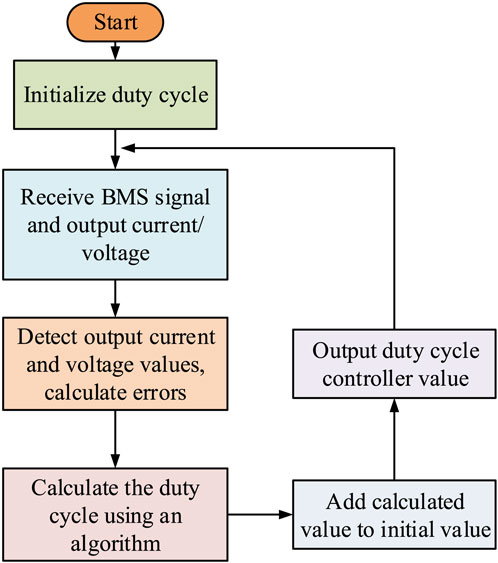
Figure 4. Main flow of secondary controller.
The control process of the secondary side in Figure 4 initializes the duty cycle first. Then the voltage and current data of the BMS signal are output, the output data is detected, and the error value is calculated. Afterwards, the duty cycle is calculated using an algorithm, which adds or subtracts the calculated duty cycle and the initialized duty cycle. Finally, the controller value for the duty cycle is output. The current and voltage of the BMS signal based on the final value are set. The entire process is controlled in a loop. Automobile in constant voltage or current, fuzzy algorithm control object is different. The parameters are used to control these two stages, which may lead to slow or too fast charging during the adjustment process, and cause damage to the car. Therefore, it is necessary to use different parameters for control at different stages.
After implementing fuzzy algorithm and optimal efficiency point tracking control, a controller is added to the system for system construction. There are two ways to implement fuzzy algorithms. One method is to use a hardware fuzzy controller, and another is software. The hardware controller is more convenient, which has a faster speed. The disadvantage is that it requires variable processing (Amir et al., 2023; Zhang G. et al., 2023b; Chobe et al., 2023). Therefore, for the fuzzy algorithm of optimal efficiency point system control, the process is shown in Figure 5.
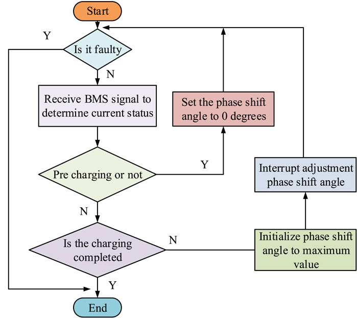
Figure 5. Fuzzy algorithm optimal efficiency point system control process.
In Figure 5, the system fault is first judged. If there is a fault, the system is shut down and ends directly. If there is no fault, the system receives electric vehicle signals normally to determine the charging status of the electric vehicle. Whether to perform pre charging is judged. If it is, the phase shift angle in the converter is set to 0. Then whether it is in a faulty charging state is determined. If not, the current charging state is determined. If it is in the end state, the process will terminate directly. If not, the phase shift angle is initialized to the maximum value, the phase shift angle is adjusted, and then whether it is in the fault charging state is determined. The magnitude of the phase shift angle determines the current charging state, the tram load, and the mutual inductance. During the charging process of an electric vehicle, either the current or the voltage is kept constant, and a change in the phase shift angle will cause a change in the output current on the primary side. To maintain the stability of the output current or voltage, the secondary side controller will adjust the duty cycle of the controllable rectifier. Therefore, although the input power fluctuates, it is possible to wait until the input and output power is stabilized by means of a timed interrupt. In this way, based on the sampled values of the stabilized input currents and voltages, the next phase shift angle adjustment can be calculated more accurately (Barman et al., 2023; Zhou et al., 2023). To increase the reliability of the control, the system compares the input power with the preset output power values. If the input power is found to be less than the preset output power after a period of waiting, this indicates that the output power has not reached the desired target. At this time, it is necessary to reduce the phase shift angle to meet the output requirements of the system. In addition, a maximum phase shift angle needs to be set to ensure that the phase shift angle is controlled within an appropriate range (Acharige et al., 2023; Vladimir and Iurii, 2023).
4 Analysis of automobile optimal efficiency point affiliation and automatic control of each charging stage
The different systems and charging states of electric vehicles in different forms are compared to obtain a more perfect optimal efficiency point and control of electric vehicle charging state. The experimental parameters are shown in Table 2. The simulation parameters are shown in Table 3.

Table 2. Experimental parameters.

Table 3. Experimental simulation parameters.
In Tables 2, 3, all parameters are consistent with the parameter expressions in the previous chapter. Different types of topology compensation are compared. The results are shown in Figure 6.
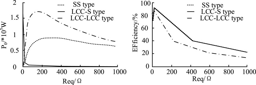
Figure 6. Comparison of three types of topology.
In Figure 6, the LCC-S type topology increased with the increase of impedance value. The output power decreased with the increase of impedance value and finally dropped to 0w. The SS topology increased with the impedance value. The output power gradually increased and began to decrease at the highest point. The highest point value at this time was 0.85*105 W. The trend of LCC-LCC topology and SS topology was consistent. However, the output power value was higher, with a maximum output power of 1.73*105 W. In Figure 6, all three topologies had optimal efficiency points. The efficiency change value first increased and then decreased with the increase of impedance. Among the three topologies, the SS type and LCC-S type had the highest optimal efficiency point of 93%. The optimal efficiency point of LCC-LCC topology was only 89%. Among the three topologies, the SS type was considered more suitable for system construction. The duty cycle represents the percentage of charging time in the total power on time. A higher duty cycle indicates a longer charging time. Therefore, controlling the duty cycle can effectively control the charging stage of electric vehicles. The algorithm control and system parameter calculation are both controlled by the secondary edge controller. The relationship between the secondary circuit and the duty cycle is shown in Figure 7.
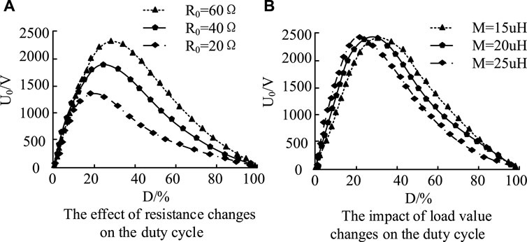
Figure 7. Relationship between secondary duty cycle and voltage change. (A) The effect of resistance changes on the duty cycle. (B) The impact of load value changes on the duty cycle.
Figure 7 shows the changes in output voltage and duty cycle of the secondary side. When the duty cycle increased, the output voltage value first rose at the highest point and then decreased. Finally, when the duty cycle was 100%, the output voltage dropped to 0 V. The highest voltage point of different resistors varied when the primary resistance of different secondary edges changed. When the resistance was 20, the duty cycle at the highest voltage value was 19.2%. When the resistance was 40, the duty cycle at the highest voltage value was 25.2%. When the resistance was 60, the duty cycle at the highest voltage value was 29.2%. The variation of mutual inductance value varied with the variation of voltage. In Figure 7, when the highest voltage value occurs and the mutual inductance value is 15 uH, the maximum duty cycle is 31%. The duty cycle for voltage peaking at a mutual inductance value of 20uH was 25%. The duty cycle at the highest point of voltage was 21% for a mutual inductance value of 25uH. From the two graphs, high voltage and lower duty cycle are beneficial for controlling the charging stage of electric vehicles, but low mutual inductance results in higher duty cycle. Therefore, the most suitable secondary circuit parameters are a resistance of 40 Ω and a mutual inductance of 20uH. The phase shift angle of the primary coil is set to 0. The simulation results of the charging stage model are shown in Figure 8.
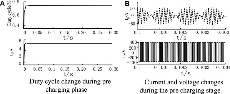
Figure 8. Simulation results of charging stage. (A) Duty cycle change during pre charging phase. (B) Current and voltage changes during the pre charging stage.
In Figure 8, the secondary current is controlled to stabilize the current. The primary output exercise and voltage waveform are observed. In Figure 8A, the duty cycle of the secondary controller was stable at around 75.6%, and the current was stable at 5A. In Figure 8B, the secondary current had low-frequency fluctuations, which may be due to the fact that the secondary controller can control the entire system’s switch. When the secondary impedance value decreases, the primary impedance value increases. This reduces the amplitude of the secondary current. When the input and output voltage value is set to 50V, the mutual inductance load changes after optimizing the primary coil are shown in Figure 9.
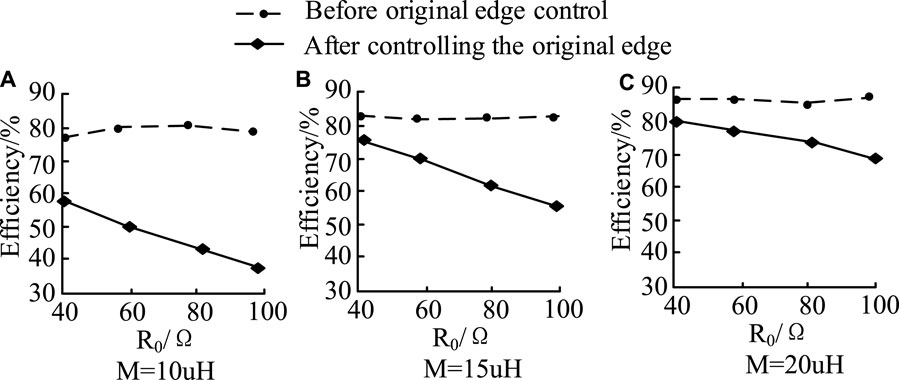
Figure 9. Mutual inductance and load changes before and after the control of the primary coil. (A) M = 10 uH, (B) M = 15 uH, (C) M = 20 uH.
In Figure 9, when the mutual inductance values were 10uH, 15uH, and 20uH, the efficiency change of the primary coil before control decreased with the increase of resistance. After controlling the primary coil, the efficiency changes almost unchanged as the resistance increases. Because when there is only secondary control, the change in efficiency is only related to the duty cycle of the secondary coil. After adding the primary coil, the overall efficiency change was determined by two parameters. After controlling the voltage, the parameters remained almost unchanged. Therefore, efficiency remained almost unchanged at the highest point. However, as the load increased, the efficiency of the coil correspondingly increases by 5% for every 5uH increase in load. The simulation results during the charging phase with a load value of 20uH are shown in Figure 10.
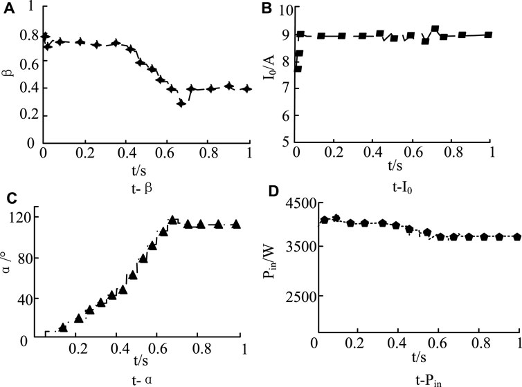
Figure 10. Simulation results of a load value of 20uH during the charging phase. (A) t-β, (B) t-I0, (C) t-α, (D) t-Pin.
In Figure 10A, the load value of the parameter decreased first and then briefly increased with time, and finally tended to stabilize, which may be due to the phase angle tends to a stable state in Figure 10C. In Figure 10B, the change of current with the increase of time first appeared a brief increase, and then tended to a relatively stable state, which may be the reason for the sudden increase of current and then stabilize the input after just plugging in the power supply in the charging phase. In Figure 10C, the change in phase angle increased slowly with time and then tended to a relatively stable state. The short time after stabilization indicates that the phase angle changes more rapidly during the charging phase. In Figure 10D, the input power showed a decreasing trend with the increase of time. Compared with Figure 10C, the value of the power change began to stabilize after the phase angle was gradually stabilized. It indicates that the phase angle is able to control the input power of the car in the charging stage. To compare the effects of different methods on the charging process of electric vehicles, the study is compared with the same car environment to test the efficiency changes of the car during the three stages of constant current, constant voltage, and charging completion. Then it is compared with the fuzzy C-means clustering, Genetic Algorithm, Particle Swarm Optimization and Fuzzy Sliding Mode Control, as shown in Table 4.
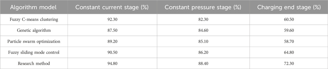
Table 4. Comparison of the effects of different methods and algorithms.
From Table 4, the research method showed high charging efficiency at different stages of the charging process, and the charging efficiency of the research method reached 94.80% in the constant current process, which was close to the optimal efficiency value of 95% in the constant current state. In the constant voltage process, the efficiency value of the research method was 88.40%, which was significantly better than other methods. Its efficiency value basically reaches 90% of the optimal efficiency value in general. At the end of the charging stage, the efficiency value of the research method was 72.30%. It shows that the method is more effective in charging the car with less energy loss at the end of the charging stage. The algorithmic criteria and content description of the fuzzy algorithm are shown in Table 5.
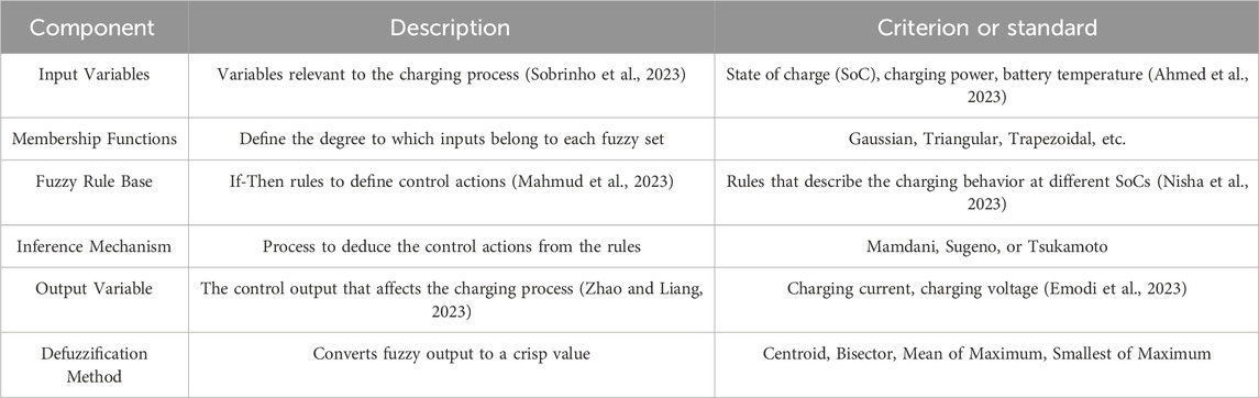
Table 5. Algorithmic judgment criteria and guidelines.
Several control models commonly used in automobiles are compared with the research method, including PID controller, genetic algorithm and particle swarm optimization algorithm for comparative testing. The simulation parameters in different cases are kept the same, and the test temperature of the car is kept the same. The charging time is about 9 h, as shown in Table 6.
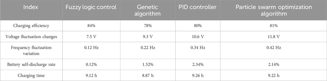
Table 6. Comparison of car parameters of different methods.
From Table 6, the fuzzy control method used in the study showed better performance in car charging control under the same conditions. The charging efficiency of the car was the highest among the four methods at 84%, which was a 6% improvement than the lowest genetic algorithm control. The charging voltage amplitude change value was also relatively low, only at 7.5 V. The self-discharge efficiency and charging time are the least among the several models, which shows that the method used in the study has the best control effect on car charging.
5 Conclusion
This research is to control the different charging stages of electric vehicles and control their automatic charging. The optimal efficiency point of the electric vehicle was firstly designed as a scheme. Then the fuzzy logic algorithm was integrated to achieve the optimal efficiency point and charging control during the charging stage of electric vehicles. From the experimental results, among the three topology compensation types, the optimal efficiency point of SS type and LCC-S type were both highest at 93%, while the optimal efficiency point of LCC-LCC type topology was only 89%, and the highest electric power of SS type was 0.85*105 W, which was considered more suitable for system construction. The maximum duty cycle of the system was 31% at a mutual inductance value of 15uH. When the secondary coil stabilized, the duty cycle stabilized at about 75.6%, and the current stabilized at 5A. At mutual inductance values of 10, 15, and 20 uH, respectively, the efficiency change of the coil was correspondingly increased by 5% for every 5uH load growth. Many data in the experiment can reflect the changes in the charging status of electric vehicles, so the control system can track and control electric vehicles. Although the experiment has achieved a lot of results, the research still has problems. Since the experimental data is only for the simulation experiment, the real data will be explored subsequently. Secondly, the coils in the research are the secondary side coils. There is less research on the primary side coils, which will continue to be explored in the future.
Data availability statement
The original contributions presented in the study are included in the article/Supplementary Material, further inquiries can be directed to the corresponding author.
Author contributions
XW: Conceptualization, Data curation, Resources, Supervision, Validation, Writing–original draft. YL: Formal Analysis, Investigation, Methodology, Project administration, Writing–review and editing.
Funding
The author(s) declare that financial support was received for the research, authorship, and/or publication of this article. The research is supported by Tianjin Vocational University Education Reform Project: Exploration and Practice of New Form's Teaching Materials integrating Post Course Competition and Certification. Project number: JGZX2023010.
Conflict of interest
Author YL was employed by Tianjin Yantuo Technology Co., LTD.
The remaining author declares that the research was conducted in the absence of any commercial or financial relationships that could be construed as a potential conflict of interest.
Publisher’s note
All claims expressed in this article are solely those of the authors and do not necessarily represent those of their affiliated organizations, or those of the publisher, the editors and the reviewers. Any product that may be evaluated in this article, or claim that may be made by its manufacturer, is not guaranteed or endorsed by the publisher.
References
Aatabe, M., Guezar, F. E., Vargas, A. N., and Hassane, B. (2021). A novel stochastic maximum power point tracking control for off-grid standalone photovoltaic systems with unpredictable load demand. Energy 235 (10), 2–13.
Acharige, S. S., Haque, M. E., Arif, M. T., Hosseinzadeh, N., Hasan, K. N., and Oo, A. M. T. (2023). Review of electric vehicle charging technologies, standards, architectures, and converter configurations. IEEE Access 14 (6), 41218–41255. doi:10.1109/access.2023.3267164
Ahin, M. E. (2020). A photovoltaic powered electrolysis converter system with maximum power point tracking control. Int. J. Hydrogen Energy 45 (16), 9293–9304. doi:10.1016/j.ijhydene.2020.01.162
Ahmed, I., Rehan, M., Basit, A., Tufail, M., and Hong, K. S. (2023). Neuro-fuzzy and networks-based data driven model for multi-charging scenarios of plug-in-electric vehicles. IEEE Access 11 (6), 87150–87165. doi:10.1109/access.2023.3303963
Amir, M., Zaheeruddin, H. A., Bakhsh, F. I., Kurukuru, V. B., and Sedighizadeh, M. (2023). Intelligent energy management scheme-based coordinated control for reducing peak load in grid-connected photovoltaic-powered electric vehicle charging stations. IET Generation, Transm. Distribution 15 (10). doi:10.1049/gtd2.12772
Badoud, A. E., Ayat, Y., and Mekhilef, S. (2021). Development and experimental validation of novel robust MPPT controller based on bond graph and fuzzy logic for PV system under variable weather conditions. Int. Trans. Electr. Energy Syst. 31 (11), 1–20. doi:10.1002/2050-7038.13091
Barman, P., Dutta, L., Bordoloi, S., Kalita, A., Buragohain, P., Bharali, S., et al. (2023). Renewable energy integration with electric vehicle technology: a review of the existing smart charging approaches. Renew. Sustain. Energy Rev. 183 (9), 113518–113519. doi:10.1016/j.rser.2023.113518
Bhukya, L., and Nandiraju, S. (2020). A novel photovoltaic maximum power point tracking technique based on grasshopper optimized fuzzy logic approach. Int. J. Hydrogen Energy 45 (16), 9416–9427. doi:10.1016/j.ijhydene.2020.01.219
Bo, C., Jiangping, H., and Bijoy, G. (2023). Finite-time observer based tracking control of heterogeneous multi-AUV systems with partial measurements and intermittent communication. Sci. CHINA Inf. Sci., doi:10.1007/s11432-023-3903-6
Chobe, P. S., Padale, D. B., Pardeshi, D. B., Borawake, N. M., and William, P. (2023). “Deployment of framework for charging electric vehicle based on various topologies,” in 2023 International Conference on Artificial Intelligence and Knowledge Discovery in Concurrent Engineering (ICECONF), Chennai, India, January, 2023, 1–4. doi:10.1109/ICECONF57129.2023.10084062
David, D. M., Codorniu, R. T., Giral, R., and Vazquez, S. L. (2021). Evaluation of particle swarm optimization techniques applied to maximum power point tracking in photovoltaic systems. Int. J. Circuit Theory Appl. 49 (7), 1849–1867. doi:10.1002/cta.2978
El-Samahy, A. A., Elzoghby, H. M., Harby, M. E. M., and Elsamahy, A. A. (2020). Microgrid frequency stability enhancement through controlling electric vehicles batteries based on fuzzy logic controller. Int. Rev. Automatic Control 13 (5), 214–223. doi:10.15866/ireaco.v13i5.19379
Emodi, N. V., Akuru, U. B., Dioha, M. O., Adoba, P., Kuhudzai, R. J., and Bamisile, O. (2023). The role of Internet of Things on electric vehicle charging infrastructure and consumer experience. Energies 16 (10), 4248–4249. doi:10.3390/en16104248
Fang, Y., Luo, B., ZhaoST-Sigma, T., He, D., Jiang, B., and Liu, Q. (2022). ST-SIGMA: spatio-temporal semantics and interaction graph aggregation for multi-agent perception and trajectory forecasting. CAAI Trans. Intell. Technol. 7 (4), 744–757. doi:10.1049/cit2.12145
Guo, C., and Hu, J. (2023). Time base generator based practical predefined-time stabilization of high-order systems with unknown disturbance. IEEE Trans. Circuits Syst. II Express Briefs 70, 2670–2674. doi:10.1109/TCSII.2023.3242856
Han, X., Wei, Z., Hong, Z., and Zhao, S. (2020). Ordered charge control considering the uncertainty of charging load of electric vehicles based on Markov chain. Renew. Energy 161 (10), 419–434. doi:10.1016/j.renene.2020.07.013
Kavya, M., and Jayalalitha, S. (2021). A novel coarse and fine control algorithm to improve Maximum Power Point Tracking (MPPT) efficiency in photovoltaic system. ISA Trans. 121 (5), 180–190. doi:10.1016/j.isatra.2021.03.036
Kumar, V., and Sharma, V. (2021). Electric vehicle integrated MPC scheme for concurrent control of voltage and frequency in power system network. Wind Eng. 46 (2), 529–544. doi:10.1177/0309524x211036424
Li, K., Saravanan, S., and Sivakumaran, T. S. (2021). A hybrid technique used in grid integration of photovoltaic system for maximum power point tracking with multilevel inverter. Trans. Inst. Meas. Control 43 (1), 215–227. doi:10.1177/0142331220964101
Liu, Z., Wu, Y., and Feng, J. (2023). Competition between battery switching and charging in electric vehicle: considering anticipated regret. Environ. Dev. Sustain., doi:10.1007/s10668-023-03592-4
Lu, Y., Tan, C., Ge, W., Zhao, Y., and Wang, G. (2023). Adaptive disturbance observer-based improved super-twisting sliding mode control for electromagnetic direct-drive pump. Smart Mater. Struct. 32 (1), 017001. doi:10.1088/1361-665X/aca84e
Luo, R., Peng, Z., Hu, J., and Ghosh, B. K. (2023). Adaptive optimal control of affine nonlinear systems via identifier–critic neural network approximation with relaxed PE conditions. Neural Netw. 167, 588–600. doi:10.1016/j.neunet.2023.08.044
Lyu, W., Hu, Y., Liu, J., Chen, K., Liu, P., Deng, J., et al. (2024). Impact of battery electric vehicle usage on air quality in three Chinese first-tier cities. Sci. Rep. 14 (1), 21. doi:10.1038/s41598-023-50745-6
Mahmud, I., Medha, M. B., and Hasanuzzaman, M. (2023). Global challenges of electric vehicle charging systems and its future prospects: a review. Res. Transp. Bus. Manag. 49 (5), 101011–101012. doi:10.1016/j.rtbm.2023.101011
Mirza, A. F., Mansoor, M., Zhan, K., and Qiang, L. (2021a). High-efficiency swarm intelligent maximum power point tracking control techniques for varying temperature and irradiance. Energy 228 (1), 120602–120631. doi:10.1016/j.energy.2021.120602
Mirza, A. F., Mansoor, M., Zhan, K., and Qiang, L. (2021b). High-efficiency swarm intelligent maximum power point tracking control techniques for varying temperature and irradiance. Energy 228 (1), 120602–120632. doi:10.1016/j.energy.2021.120602
Nasab, M. A., Al-Shibli, W. K., Zand, M., Ehsan-maleki, B., and Padmanaban, S. (2024). Charging management of electric vehicles with the presence of renewable resources. Renew. Energy Focus 48, 100536. doi:10.1016/j.ref.2023.100536
Nasab, M. A., Zand, M., Dashtaki, A. A., Nasab, M. A., Padmanaban, S., Blaabjerg, F., et al. (2023). Uncertainty compensation with coordinated control of EVs and DER systems in smart grids. Sol. Energy 263, 111920. doi:10.1016/j.solener.2023.111920
Nisha, K. S., Gaonkar, D. N., and Jayalakshmi, N. S. (2023). Operation and control of multiple electric vehicle load profiles in bipolar microgrid with photovoltaic and battery energy systems. J. Energy Storage 57 (7), 106261–106262. doi:10.1016/j.est.2022.106261
Shao, B., Xiao, Q., Xiong, L., Wang, L., Yang, Y., Chen, Z., et al. (2023). Power coupling analysis and improved decoupling control for the VSC connected to a weak AC grid. Int. J. Electr. Power & Energy Syst. 145, 108645. doi:10.1016/j.ijepes.2022.108645
Shen, Y., Xie, J., He, T., Yao, L., and Xiao, Y. (2024). CEEMD-fuzzy control energy management of hybrid energy storage systems in electric vehicles. IEEE Trans. Energy Convers. 39 (1), 555–566. doi:10.1109/TEC.2023.3306804
Sobrinho, D. M., Almada, J. B., Tofoli, F. L., Leão, R. P. S., and Sampaio, R. F. (2023). Distributed control based on the consensus algorithm for the efficient charging of electric vehicles. Electr. Power Syst. Res. 218 (5), 109231–109232. doi:10.1016/j.epsr.2023.109231
Vanitha, V., Resmi, R., and Reddy, K. N. S. V. (2020). Machine learning-based charge scheduling of electric vehicles with minimum waiting time. Comput. Intell. 37 (3), 1047–1055. doi:10.1111/coin.12333
Vladimir, P., and Iurii, P. (2023). Supercapacitor energy storages in hybrid power supplies for frequency-controlled electric drives: review of topologies and automatic control systems. Energies 16 (7), 3287–3288. doi:10.3390/en16073287
Wang, J., Liu, Q., and Jing, S. (2021a). Vehicle-Mounted photovoltaic system energy management in intelligent transportation systems: a maximum power point tracking control. Complexity 2021 (5), 1–9. doi:10.1155/2021/5578972
Wang, J., Liu, Q., and Jing, S. (2021b). Vehicle-mounted photovoltaic system energy management in intelligent transportation systems: a maximum power point tracking control. Complexity 2021 (6), 1–9. doi:10.1155/2021/5578972
Wang, Y., Chen, P., Yong, J., Xu, W., Xu, S., and Liu, K. (2022). A comprehensive investigation on the selection of high-pass harmonic filters. IEEE Trans. Power Deliv. 37 (5), 4212–4226. doi:10.1109/TPWRD.2022.3147835
Wang, Y., Xia, F., Wang, Y., and Xiao, X. (2023). Harmonic transfer function based single-input single-output impedance modeling of LCCHVDC systems. J. Mod. Power Syst. Clean Energy. doi:10.35833/MPCE.2023.000093
Xu, J., Zhao, Y., Zhan, Y., and Yang, Y. (2021). Maximum power point tracking control for mechanical rectification wave energy converter. IET Renew. Power Gener. 15 (14), 3138–3150. doi:10.1049/rpg2.12213
Yang, C., Wu, Z., Li, X., and Fars, A. (2024). Risk-constrained stochastic scheduling for energy hub: integrating renewables, demand response, and electric vehicles. Energy 288, 129680. doi:10.1016/j.energy.2023.129680
Yang, M. (2022). Research on vehicle automatic driving target perception technology based on improved MSRPN algorithm. J. Comput. Cognitive Eng. 1 (3), 147–151. doi:10.47852/bonviewjcce20514
Zhang, G., Dai, M., Zhao, S., and Zhu, X. (2023b). Orderly automatic real-time charging scheduling scenario strategy for electric vehicles considering renewable energy consumption. Energy Rep. 9 (6), 72–84. doi:10.1016/j.egyr.2022.11.164
Zhang, K., Ye, T., Yan, Z., Song, B., and Hu, A. P. (2020b). Obtaining maximum efficiency of inductive power-transfer system by impedance matching based on boost converter. IEEE Trans. Transp. Electrification 6 (2), 488–496. doi:10.1109/tte.2020.2987487
Zhang, L., Guo, X., Yang, L., Peng, Y., and Qi, B. (2020a). Active synchronising control of dual-mode coupling transmission for electric vehicles. Int. J. Veh. Des. 2020 (1/4), 75–96. doi:10.1504/IJVD.2020.113921
Zhang, X., Lu, Z., Yuan, X., Wang, Y., and Shen, X. (2021). L2-Gain adaptive robust control for hybrid energy storage system in electric vehicles. IEEE Trans. Power Electron. 36 (6), 7319–7332. doi:10.1109/tpel.2020.3041653
Zhang, X., Wang, Y., Yuan, X., Shen, Y., and Lu, Z. (2023a). Adaptive dynamic surface control with disturbance observers for battery/supercapacitor-based hybrid energy sources in electric vehicles. IEEE Trans. Transp. Electrification 9 (4), 5165–5181. doi:10.1109/tte.2022.3194034
Zhang, X., Wang, Z., and Lu, Z. (2022). Multi-objective load dispatch for microgrid with electric vehicles using modified gravitational search and particle swarm optimization algorithm. Appl. Energy 306, 118018. doi:10.1016/j.apenergy.2021.118018
Zhao, L., Qu, S., Xu, H., Wei, Z., and Zhang, C. (2024). Energy-efficient trajectory design for secure SWIPT systems assisted by UAV-IRS. Veh. Commun. 45, 100725. doi:10.1016/j.vehcom.2023.100725
Zhao, X., and Liang, G. (2023). Optimizing electric vehicle charging schedules and energy management in smart grids using an integrated GA-GRU-RL approach. Front. Energy Res. 11 (6), 1268513–1268514. doi:10.3389/fenrg.2023.1268513
Keywords: electric vehicles, optimal efficiency point membership, automatic control, fuzzy logic, intelligent charging
Citation: Wang X and Li Y (2024) Optimal efficiency point membership incorporating fuzzy logic and automatic control of various charging stages for electric vehicles. Front. Mech. Eng 10:1390341. doi: 10.3389/fmech.2024.1390341
Received: 23 February 2024; Accepted: 10 April 2024;
Published: 24 May 2024.
Edited by:
Adel Razek, UMR8507 Laboratoire Génie électrique et électronique de Paris (GeePs), FranceReviewed by:
Lei Zhang, Beijing Institute of Technology, ChinaFlah Aymen, École Nationale d’Ingénieurs de Gabès, Tunisia
Morteza Azimi Nasab, Eastern Norway Research Institute, Norway
Copyright © 2024 Wang and Li. This is an open-access article distributed under the terms of the Creative Commons Attribution License (CC BY). The use, distribution or reproduction in other forums is permitted, provided the original author(s) and the copyright owner(s) are credited and that the original publication in this journal is cited, in accordance with accepted academic practice. No use, distribution or reproduction is permitted which does not comply with these terms.
*Correspondence: Xinyan Wang, d3h5dGp6eWR4QDE2My5jb20=