- Aerospace Research Institute, Ministry of Science, Research, and Technology, Tehran, Iran
This paper presents a comprehensive review of the studies and research conducted on flow separation control on lifting surfaces. In this paper, two critical parameters, namely, the momentum coefficient and excitation frequency, that significantly impact flow separation control are analyzed in detail. Through a comprehensive literature review, experimental and numerical studies are examined in order to gain insight into the underlying mechanisms of momentum injection and excitation frequency on the shear layer and wake dynamics and to quantify the impact of these parameters on the flow separation control. Effective flow control on lifting surfaces can modify the streamlines and pressure distribution, thereby increasing their aerodynamic efficiency. This paper focuses on the control of flow separation on airfoils, with particular attention paid to the benefits of such control, including lift enhancement, drag reduction, aerodynamic efficiency enhancement, performance enhancement, and other important features. This paper presents a review of studies that have employed blowing actuators, as well as zero net mass flux, plasma, and acoustic actuators, in order to provide an appropriate historical context for recent developments. The findings of this review paper will contribute to a better understanding of the optimal conditions for efficient flow separation control on lifting surfaces using unsteady excitation, which can have significant implications for improving the performance and efficiency of various aerodynamic applications. This paper aims to elucidate and emphasize the positive and negative aspects of existing research, while also suggesting new interesting areas for future investigation.
1 Introduction
1.1 Flow separation phenomenon
In general, flow separation refers to the detachment of fluid flow from a solid surface, commonly referred to as a wall. The velocity of viscous fluid particles in the boundary layer adjacent to the wall decreases due to friction and shear stress exerted by the wall. On the other hand, when a viscous fluid flow encounters an adverse pressure gradient, it tends to separate. Thus, if the flow velocity undergoes a significant deceleration due to the presence of an adverse pressure gradient, the momentum of the fluid particles is concurrently reduced by both the wall shear stress and the adverse pressure gradient. From an energy perspective, the kinetic energy gained from converting potential energy in the favorable pressure gradient region is diminished by the effects of viscosity in the boundary layer. In the region with an adverse pressure gradient, the remaining kinetic energy is converted into potential energy. However, this energy is insufficient to overcome the pressure forces, causing the movement of fluid particles near the wall to eventually cease. At this point, the viscous layer separates from the surface at a specific point (or line), and the streamlines closest to the surface separate from the wall, creating a rotational flow region near the surface. In this case, it is said that the boundary layer is separated. During the occurrence of flow separation, there is a sudden thickening of the rotational flow region close to the wall, and the normal velocity component increases to the extent that the approximations used for the boundary layer are no longer valid.
The phenomenon of flow separation is of great importance in the operation of a wide range of technological systems, including air, land, and sea vehicles, turbomachines, diffusers, and other important systems involved with fluid flow. Flow separation on the lifting surface typically occurs just prior to or at the point of maximum loading, with a significant impact on the optimal performance of the device (Gad-el-Hak, 2006). To provide further clarification, during the take-off phase of an aircraft, when the aircraft is still at low speeds, it is necessary to maximize lift by increasing the angle of attack of the wing. Elevating the angle of attack enhances the production of lift, enabling the aircraft to achieve liftoff at lower airspeeds and maximum loading. However, it is essential to exercise caution, as exceeding a certain angle of attack threshold can trigger a stall. A stall occurs when the angle of attack exceeds a critical threshold, resulting in airflow separation and the disruption of lift generation, which may result in a loss of altitude or the loss of aircraft control.
In general, the flow topology, which includes the occurrence of flow separation around an aerodynamic body or any other surface, is determined by boundary conditions such as surface geometry, Reynolds number, and Mach number. Therefore, when designing such devices, engineers optimize the effective parameters to avoid flow separation or postpone it as much as possible to increase system efficiency. For instance, delaying flow separation can reduce the pressure drag of a bluff body, increase the circulation and lift of a wing at a high angle of attack, and improve the pressure recovery of the diffuser (Gad-el-Hak, 2006). Due to significant energy losses caused by the separation of the boundary layer, the performance of numerous practical devices can be constrained by the location where separation occurs. Consequently, the utilization of flow separation control technology represents an efficient solution in many fluid dynamics applications, whereby the consumption of energy is reduced and the performance of the system is enhanced.
The field of aviation offers considerable potential for the application of flow separation control methods. Pioneering researchers in the field of aviation have investigated and employed a variety of boundary layer control methods with the objective of enhancing lift. Airfoils with conventional profiles experience significant aerodynamic performance degradation at low Reynolds numbers when Re < 1 × 10⁶, due to laminar boundary layer separation near the leading edge (Lissaman, 1983). Compared to high Reynolds number flows, airfoils with low Reynolds numbers experience flow separation at a lower angle of attack, even at zero angle of attack (Yarusevych et al., 2009). Downstream of the separation point, two states may occur. In the first case, the shear layer of the separated flow can reattach to the airfoil surface downstream of the separation point, creating a closed recirculation region in the time-averaged sense. This region is known as laminar separation bubble (LSB). In the second case, the flow may remain separated, which is known as stall. For flows with high Reynolds numbers, stall conditions occur after the turbulent flow separates. Compared to the airflow that remains attached to the airfoil surface along the chord, both of these phenomena typically result in a decrease in lift and an increase in drag on the airfoil. These adverse effects are more pronounced during stall and post-stall conditions, leading to high energy consumption in the aviation industry. In this regard, extensive research has been conducted on implementing boundary layer control strategies to promote flow reattachment on the airfoil surface and mitigate the unfavorable effects caused by post-stall conditions. These studies investigated the fundamental concepts underlying flow separation control and introduced various methods of momentum transfer using active and passive actuators, along with the factors influencing these methods.
The objective of this article is to present a comprehensive review of the studies and research conducted on flow separation control on lifting surfaces, with a particular focus on airfoils. Furthermore, two critical parameters that have a significant impact on flow separation control will be analyzed in detail. The main emphasis of this paper is to investigate the impact of momentum coefficient and excitation frequency as actuation parameters on flow separation control using unsteady excitation. In this study, the effective excitation frequency and the effective momentum coefficient are reported based on the objective of enhancing lift, reducing drag, or a combination of both in the pertinent research. Firstly, a concise overview of the different active separation control methods, namely, steady and unsteady, along with their respective advantages and disadvantages, is presented. Subsequently, this article reviews experimental and numerical simulation findings from recent years that highlight and emphasize the influence of the momentum coefficient and excitation frequency on active separation control. Finally, the latest developments in this field and potential applications are discussed, along with the challenges that arise from a control system perspective. Furthermore, suggestions for future research and development are provided.
1.2 Flow control
Numerous definitions have been proposed for flow control, exhibiting apparent differences, yet ultimately sharing the same concept. Fiedler and Fernholz (Fiedler and Fernholz, 1990) presented a comprehensive definition, stating that flow control is a process or operation through which certain flow properties are controlled and directed in a desired manner, based on user requirements. Among the various types of shear flow control methods available, flow separation control, historically referred to as boundary layer control, stands out as the oldest and most economically significant. Flatt’s definition (Flatt, 1961) of controlling wall-bounded flows encompasses any mechanism or process that alters the behavior of the boundary layer from its natural state. Prandtl’s introduction of boundary layer theory, accompanied by a description of several experiments involving boundary layer control, positions Prandtl as a pioneer in the field of flow control. Indeed, the earliest recognition of the potential to modify flow by influencing the boundary layer can be attributed to Prandtl’s early work (Gad-el-Hak, 2006). Since then, flow control technology has been systematically researched and studied, leading to a deeper understanding of the determining parameters for the effectiveness and efficiency of flow control.
The ability to manipulate the flow pattern of the boundary layer in a desired manner holds significant practical importance across various industries. In general, methods of boundary layer control aim to either delay or accelerate the transition of the boundary layer. These actions, respectively, inhibit or enhance the generation of turbulence within the flow. This process effectively promotes or prevents flow separation, resulting in notable outcomes and achievements. Notable achievements in boundary layer flow control include the reduction of drag, augmentation of lift, enhancement of heat transfer in fluids, improved mixing, noise reduction, and the mitigation of flow-induced disturbances.
Flow control technologies can be categorized into passive and active methods. Passive control methods involve manipulating the flow without introducing external energy, relying solely on the redistribution of energy and momentum to achieve the desired flow characteristic. These methods typically impose minimal additional weight on the main system. Examples of industrially used passive flow separation control methods include vortex generators on Boeing aircraft wings, blown flaps on older generation supersonic fighters, leading edge extensions, and the implementation of strakes on newer generation airplanes. However, one drawback of passive methods is their reduced efficiency when flow conditions change, such as increasing Reynolds number or altering the angle of attack on wings and blades, which can even negatively impact overall system efficiency. On the other hand, active control methods involve the addition of energy through a control actuator. This approach utilizes an external energy source to introduce high-momentum fluid into the flow or extract low-momentum fluid from it. In essence, the active flow control method entails the exchange of energy, mass, or other auxiliary forces between the environment and the fluid. Compared to passive control, active control offers greater efficiency in flow control as it can be deactivated when not needed. Nevertheless, the implementation of active control necessitates additional weight and energy consumption.
In both active and passive control methods, various physical mechanisms are employed to achieve the desired effect, depending on the type of control. In the context of separation control, the primary challenge is to add momentum to the region close to the wall, given the applied pressure field. This is accomplished by transferring momentum from regions of the flow that are distant from the wall, where momentum is still abundant, to regions near the wall with lower momentum. Alternatively, momentum and power can be directly injected from the propulsion system. The most well-known technique for controlling flow separation is to add momentum in the near-wall region in a manner that is either active, such as tangential blowing or wall jets, or passive, such as vortex generators at different scales, as illustrated in Figure 1.
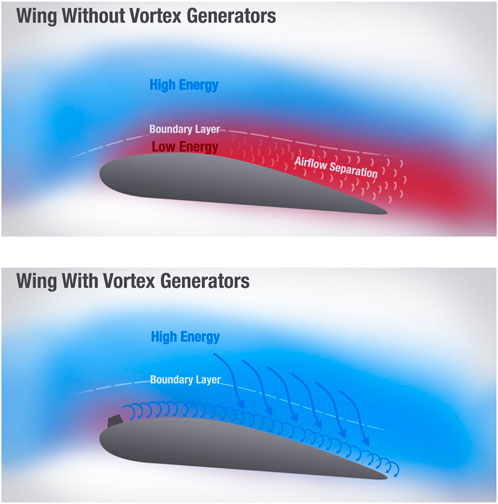
Figure 1. Flow separation control using a vortex generator on an airfoil (Udris, 2024).
Active flow control methods can be categorized based on whether there is a net mass flux accompanied by an input of energy and momentum, as well as whether this addition occurs in a steady or unsteady manner. In the field of aviation, pioneering researchers have identified steady suction and blowing as the most commonly employed boundary layer control methods. In the case of boundary layer suction, the removal of low-momentum fluid creates a sink on the aerodynamic surface, which accelerates the flow towards the suction location and promotes a more stable boundary layer (Schlichting and Gersten, 2016). Here, both the effect of removing the low-momentum fluid and accelerating the flow are desirable in delaying the separation. In a flight test conducted by Hunter and Johnson (Hunter and Johnson, 1954), leading edge suction was utilized to eliminate flow separation occurring on a thin airfoil. Raspet (Raspet, 1951; Raspet, 1952), conducted experiments through distributed suction to control the transition of the laminar boundary layer and separation of the turbulent boundary layer. Remarkably, he was able to maintain the laminar boundary layer for over 95% of the wing chord of a TG-3A glider. Furthermore, Cornish (Cornish, 1953) employed distributed suction on the wing of a TG-3A glider and successfully increased the maximum lift coefficient from 1.38 to 2.28. In the subsequent step, this approach was employed on the L-21 motor plane, resulting in a notable enhancement of the maximum lift coefficient to 3.98 (Raspet et al., 1956).
In the case of steady blowing, an air jet, which is typically oriented tangentially or at an angle to the local curvature of the surface, injects high-momentum fluid directly into the boundary layer. This jet injects high-momentum fluid directly into the boundary layer, thereby augmenting the mixing rate of the fluid near and away from the wall and re-energizing the boundary layer (Jones et al., 2006). The combination of tangential steady blowing with the implementation of a Coanda surface, as exemplified by the design of a circular trailing edge of an airfoil in Figure 2, results in an increase in both the virtual chord length and the chamber of the airfoil. Consequently, this configuration yields a substantial boost in lift (Kweder et al., 2010; Kweder et al., 2014; Du et al., 2022).
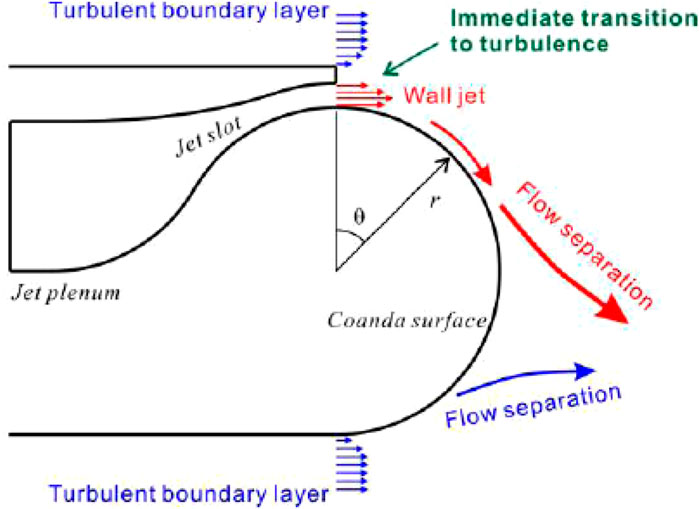
Figure 2. The concept of circulation control and Coanda effect influence on the airfoil’s trailing edge and streamlines (Nishino et al., 2010).
In the 1920s, concepts of boundary layer control were investigated by aeronautical engineers for lift enhancement. Baumann (Betz and Lachmann, 1961) obtained a patent for utilizing air jets emanating from wing slots for flow separation control and lift augmentation. The first documented instance of employing a steady air jet to enhance the lift in the United States was reported by Knight and Bamber in 1929 (Knight and Bamber, 1929). Their investigation focused on the impact of air jet slot geometry, slot location and jet flow rate on lift enhancement. The experimental findings revealed a remarkable 151% increase in aerodynamic efficiency, as measured by the lift-to-drag ratio, for a two-dimensional airfoil. A concise overview of the development of boundary layer control through steady suction and blowing techniques can be found in reference (Joslin and Miller, 2009).
Currently, due to the high power and momentum requirements in the steady flow control method, the boundary layer control by the unsteady technique has been widely considered. This approach involves the application of suction and blowing, or solely blowing, in an oscillating or pulsed condition. The technique of unsteady excitation flow control exploits the phenomenon of natural flow instability, which has the potential to reduce mass flux and enhance efficiency. In contrast to steady blowing, where the momentum content and the entrainment rate of the air jets are the primary factors influencing flow control effectiveness, unsteady excitation, typically pulsed blowing, generates vortical structures that play a pivotal role. These vortices augment the mixing rate throughout the flow field, facilitating the transfer of momentum from regions of high-momentum fluid to low-momentum fluid. Research conducted by the NASA Langley comparing steady and unsteady excitation reveals that the unsteady excitation is two orders of magnitude more efficient than the steady excitation in achieving equivalent aerodynamic benefits (Sellers et al., 2002). Over several years, researchers have demonstrated that the application of local unsteady excitation on the aerodynamic surface can lead to flow reattachment and enhance aerodynamic performance (Seifert et al., 1996; Greenblatt and Wygnanski, 2000). These studies experimentally verify the effectiveness of periodic excitation on an airfoil in delaying boundary layer separation. Furthermore, studies have demonstrated that the periodic application of suction and blowing of air through a narrow slot, extending along the wing span, can effectively enhance the mixing of the shear layer and facilitate the momentum transfer between wall-near and wall-distant fluid. By employing this approach, it effectively mitigates or postpones the occurrence of boundary layer separation. Consequently, this method increases overall lift by shifting the separation point downstream and towards the trailing edge of the airfoil.
Seifert et al. (2004) stated in their research that the unsteady active control of flow separation relies on exploiting the flow’s inherent instabilities that require a relatively small amplitude of excitation. Disturbances should strategically be amplified in regions prone to separation. Effective excitation frequencies consistently generate several vortices within the controlled region, irrespective of the Reynolds number. Unsteady excitation expedites and regulates the formation of large coherent structures, thereby facilitating the transfer of high-momentum fluid toward the surface. Despite the inherent unsteadiness of this process, it exhibits a stabilizing and regulating effect on flows susceptible to separation. Seifert et al. (2004) additionally emphasized that periodic excitation outperforms steady excitation in terms of performance benefits, eliminating unexpected flow responses that are undesirable from a control point of view. Moreover, it effectively mitigates separation-related effects such as vortex shedding and buffeting, either significantly reducing their impact or eliminating them altogether.
Seifert et al. (1996) conducted experiments demonstrating that oscillatory blowing, as opposed to steady blowing, has a more pronounced impact on controlling separation and enhancing the maximum lift coefficient of a NACA 0015 airfoil. Furthermore, their research findings indicated that introducing the jet upstream of the separation point yields a more effective separation control. Similar observations were made by Greenblatt and Wignansky (Greenblatt and Wygnanski, 2000). Bernardini et al. (2014) demonstrated that the performance of an airfoil can be enhanced by employing wall-normal pulsed jets, by amplifying the inherent instabilities of the flow. In fact, in this technique, the inherent instability is exploited to achieve the desired results. They elucidated that these pulsed jets introduce disturbances to the flow corresponding to higher-order harmonics of the excitation frequency. Consequently, specific harmonics, amplified by the natural Kelvin-Helmholtz instability, facilitate the momentum absorption and transfer, and reattachment of the flow. Numerous experimental investigations have consistently shown that unsteady excitation methods are more efficient and effective in utilizing energy from the actuators. Consequently, unsteady excitation methods are often preferred in various experiments, despite requiring a more complex drive system compared to their steady counterparts. This is due to the necessity of incorporating a mechanism capable of generating unsteady flow, which is a requisite for many experiments.
As previously stated, one of the principal advantages of active flow control, in comparison to passive methods, is its adaptability and flexibility to adjust based on varying flow conditions. This adaptability is facilitated by sensor systems that are capable of providing real-time information from either the flow field or the surface flow. The utilization of a closed-loop flow control system enables users to implement specific corrections in order to achieve the desired fluid flow through control actuators. Consequently, active flow control necessitates the implementation of an actuation system capable of delivering energy, momentum, or mass flow in the desired form and quantity. Moreover, the integration of these actuators with the main system should be feasible while meeting size and weight requirements. When considering active flow control for commercial applications, it is crucial to design actuators that possess suitable power, energy conversion efficiency, cost-effectiveness, maintainability, and reliability. Furthermore, compliance with system requirements and limitations significantly influences the design of active flow control. Therefore, the design of an active flow control system always involves parameters that directly impact the effectiveness of the control effort.
2 Effective parameters in flow separation control on the surface
The most prevalent form of flow separation control mechanism employed on a surface is the utilization of fluidic actuators that employ steady and unsteady flow injection or suction. These actuators can be categorized based on their size, ranging from macro to micro jets. They can administer fluid injection continuously at a constant flow rate or periodically and pulsed to the surface. Therefore, various parameters are involved in the design of such control systems that impact their efficiency. These parameters encompass the geometric characteristics of the actuators, such as the shape and dimensions of the jet outlet slot, the location and orientation of the jet injection relative to the target surface, as well as the physical attributes of the actuators, including the actuation amplitude or momentum coefficient, jet velocity, and actuation frequency. Furthermore, flow conditions introduce a distinct set of parameters to the system design, typically encompassing similarity parameters, Mach number, and Reynolds number. The objective of this research is to investigate two key parameters in the design of fluidic actuators: the momentum coefficient or actuation amplitude, and the actuation frequency. These parameters have a significant impact on the effectiveness of the control effort. The study will provide a comprehensive review of the existing research conducted on these two parameters.
2.1 Actuation amplitude or momentum coefficient Cμ
In the context of flow control research, the actuation amplitude represents a valuable metric for the evaluation of the efficacy of suction and blowing flow control techniques. This amplitude directly contributes to enhancing the system’s efficiency. The actuation amplitude is generally presented in normalized form. It is quantified by the momentum coefficient Cμ, as depicted in Equation 1 in its general form.
Based on this equation, the momentum coefficient Cμ can be defined as the ratio between the momentum flux generated by the flow control system J and the momentum flux of the oncoming flow, represented by the product of the freestream dynamic pressure q∞ and a reference area Aref. The precise formulation of the momentum coefficient is established by Poisson-Quinton (Joslin and Miller, 2009) in Equation 2.
In the given equation, the variables qm and Vj represent the mass flow rate and jet velocity, respectively. These variables are normalized by the dynamic pressure q∞ and the reference area Aref, respectively. The following paragraphs outline the methodology employed to determine the actuation amplitude of some unsteady flow control actuators.
Synthetic jet actuators primarily depend on two operating conditions to determine their actuation amplitude: the actuation frequency and the stroke length of the synthetic jet driver. The strain of the piezoelectric diaphragm, and consequently the driver’s stroke length, is adjusted by applying a voltage potential across the piezoelectric material. Once the actuation frequency is selected, the amplitude is solely determined by the voltage input to the piezoelectric material. In optimal systems, the fluidic amplitude correlates with the input voltage, although calibration is necessary to accurately assess the performance of each actuator. This calibration typically involves measuring the phase-averaged jet velocity at the centerline of the synthetic jet orifice using a hotwire anemometer. To comprehensively quantify the fluidic amplitude of a synthetic jet actuator, it is crucial to fully map the exit velocity profile (Smith and Gregory, 2001; Holman et al., 2005). However, for calibration purposes, assuming a plug-flow exit profile with an amplitude equivalent to the measured centerline velocity is acceptable (Shuster and Douglas, 2007). By analyzing this data, two critical benchmarks of actuator effectiveness can be determined for a specific flow control application: the blowing coefficient Cb and the momentum coefficient Cμ. The blowing ratio Cb represents a valuable metric for scaling the amplitude of a synthetic jet in accordance with the prevailing freestream conditions. This ratio is defined by Equation 3, in which Vj represents the average jet exit velocity over the blowing portion of the synthetic jet cycle, as calculated by Equation 4.
Where vj(t) is the jet exit velocity as a function of time and T is period. While the blowing coefficient is a significant measurement, it is not enough to fully evaluate the effectiveness of a synthetic jet actuator by itself. A metric that takes into account the orifice cross-sectional area is also needed to truly compare the efficiency of similar actuators. Therefore, it can be argued that the local momentum measurement added to the system is more appropriate. As a result, the time-averaged momentum coefficient Cμ is commonly used and is defined as Equation 5. The time-averaged momentum for synthetic jet actuator can be calculated as the integral of the momentum added during the expulsion phase of the synthetic jet cycle averaged over the entire period of the cycle. The numerator of the fraction in Equation 2 for synthetic jets is derived from the Equation 5:
In the context of employing solenoid valves as an actuator to produce pulsed jets, it is possible to adjust the amplitude or momentum coefficient Cμ of the pulsed jets by varying the pressure within the compressed air duct. The mass flow rate and jet velocity can be regulated by pressure regulators. Furthermore, the momentum coefficient can be determined from Equation 2 using anemometry, or calculated using a flow meter and jet’s cross-section area.
The actuation amplitude of plasma actuators can be adjusted by the input voltage applied to the actuator (Taleghani et al., 2012). The output actuation amplitude of the plasma actuator can typically be determined by measuring the velocity of the produced microjet or by measuring the momentum of the jet (Taleghani et al., 2018). Experimental results indicate that the dominant frequency of the flow vortices generated by the plasma actuators precisely corresponds to the excitation frequency of the input electric wave (Taleghani et al., 2018). In addition to voltage amplitude, other geometric and electrical parameters play a significant role in determining the amplitude of plasma actuator output excitation (Taleghani et al., 2012; Taleghani et al., 2018; Mohammadi and Taleghani, 2014; Salmasi et al., 2013; Mirzaei et al., 2012). After measuring the velocity profile of the generated microjet in a quiescent environment, the numerator of the fraction in Equation 2 is determined by Equation 6. In Equation 6, Aj represents the cross-section area of the microjet.
The amplitude of acoustic excitation in flow control methods refers to the magnitude or strength of the acoustic signals generated by the actuator to influence the fluid flow. This amplitude can be measured in various ways, including through sound pressure level (in decibels, dB), microphone recordings, or vibration measurements. The amplitude of acoustic excitation plays a crucial role in determining the effectiveness of flow control methods, as it directly impacts the intensity of the acoustic forces exerted on the fluid flow.
It is important to note that while the momentum coefficient is commonly used to quantify the actuation amplitude, it is not an appropriate parameter for comparing the benefits of flow control across different parameter settings and configurations (Stal nov and Seifert, 2010). The momentum coefficient Cμ is calculated by multiplying the mass flow rate and the velocity of mass propagation, which leads to the formation of the jet momentum flux J, as indicated in the numerator of Equation 1. This definition of Cμ reveals that numerous combinations of mass flow rate and jet velocity can yield the same value for the momentum coefficient. To address this crucial distinction between the two quantities, the parameter of jet velocity ratio VR or blowing ratio (as previously mentioned), is employed. This is defined in Equation 7.
The jet velocity ratio VR, represents the ratio of the velocity of the air jet exiting the actuator Vjet to the reference velocity Vref. The reference velocity can be the local Vx, the impingement velocity, or the freestream flow velocity V∞ of the controlled flow. Consequently, the magnitude of the air jet velocities emitted from the active flow control system is expressed through the velocity ratio or blowing ratio.
Experimental results obtained from flow control on a two-dimensional airfoil with a plain flap indicate that, when exciting the flow with the same momentum coefficient, employing a higher jet velocity ratio yields superior outcomes compared to conditions where the mass flow rate is higher and the jet velocity ratio is lower (Thomas, 1962). In the context of flow injection, it can be demonstrated that a positive effect on the flow can be achieved by ensuring that the velocity ratio of the actuation exceeds unity. (Greenblatt and Wygnanski, 2000). Otherwise, the momentum content of the boundary layer may be decreased, leading to an increased likelihood of flow separation. This detrimental effect adversely impacts aerodynamic performance (Bauer et al., 2010; Mueller-Vahl et al., 2013).
The blowing ratio has been commonly employed in studies investigating two-dimensional flow control as a means to measure the actuation amplitude, instead of the momentum coefficient. In general, for both objectives of flow control, namely, delaying flow separation or reattachment of separated flow, it has been observed that increasing the actuation amplitude or blowing ratio beyond a certain threshold limit (i.e., introducing additional input momentum) has a diminishing effect on the attached flow. This phenomenon is well-documented through the saturation of the increase in lift coefficient, as demonstrated by Packard et al. (2013) for the steady normal blowing actuation on a NACA 643-618 airfoil at two different Reynolds numbers as depicted in Figure 3. Furthermore, Packard et al. research (Packard et al., 2013) has demonstrated that the optimal blowing ratio varies in flows with different Reynolds numbers. By comparing Figures 3A,B, it is evident that at an angle of attack α = 20°, a blowing ratio BR of approximately 1 has negligible impact on the lift coefficient in the low Reynolds number flow (6.4 × 10⁴), thus failing to improve the aerodynamic characteristics. Conversely, in the high Reynolds number flow (4 × 10⁶), the blowing ratio BR ≈ 1 enhances the lift coefficient and approaches its peak performance. Consequently, it can be inferred that maintaining a constant blowing ratio for different Reynolds numbers is not ideal. The physics of flow around lifting surfaces undergoes significant changes with variations in the Reynolds number. As a result, the optimal values of flow control parameters, such as the blowing ratio, will also vary in accordance with these alterations in freestream flow characteristics.
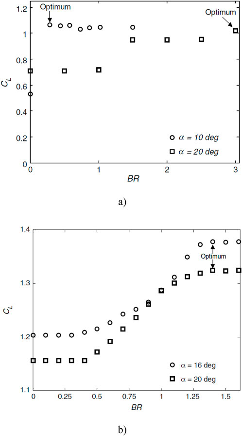
Figure 3. Variation of Lift coefficient with different blowing ratio (A) at angle of attack of 10° and 20° and Re = 6.4 × 10⁴ (B) at angle of attack of 16° and 20° and Re = 4×10⁶ (Packard et al., 2013).
In various studies, the momentum coefficient Cμ has been identified as a crucial parameter in determining the effectiveness of active flow control. It has been observed that increasing the momentum coefficient leads to enhanced control benefits. According to the research conducted by Jones and Englar (2003) on high-lift systems, actuation with a low momentum coefficient typically indicates separation control (boundary layer control), while actuation with a high momentum coefficient suggests circulation control. Their study focused on the development and testing of two-dimensional airfoil design for potential general aviation use. This model was based on 17% supercritical-type section with a circular trailing edge as a Coanda surface. They utilized dual-slot blowing on a Coanda surface for high-lift operations in both the steady state and the pulsed modes. Testing was conducted at Reynolds number of approximately 5 × 10⁵ in the wind tunnel, focusing on high lift, cruise, and mass flow optimization modes. In Jones and Englar (2003) study, the lift performance characteristics of the model in high-lift mode demonstrate the difference between separation control (boundary layer control) and super-circulation, as illustrated in Figure 4. When the jet blows with low momentum coefficients, it entrains the outer flow, causing the boundary layer to attach to the Coanda surface and turn the local streamlines (see Figure 5A). As the blowing level increases, the separation point moves around the Coanda surface towards the maximum x/C of the airfoil (i.e., x/C = 1) as shown in Figure 5B. This results in the higher momentum jet entraining with the oncoming low momentum flow from the under-surface flow field. The jet penetration creates a virtual or pneumatic flap that turns the streamlines. Increasing the blowing results in more jet penetration and entrainment, leading to greater streamline turning beyond the maximum x/C, Figure 5C. The magnitude of the jet momentum governs the penetration into the trailing edge flow field once the separation is fixed. As momentum increases, the penetration depth (length) also increases, leading to increased streamline turning and circulation. This increased circulation causes the leading edge stagnation point to move aft along the lower surface, resulting in an increase in the leading edge suction pressure and lift enhancement.
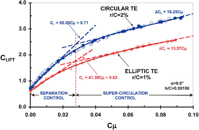
Figure 4. Effect of momentum coefficient on lift coefficient and transition from separation control (boundary layer control) to circulation control (Jones and Englar, 2003).

Figure 5. CFD simulation of the jet penetration around a Coanda surface for different momentum coefficientsCµ =, (A) 0.013, (B) 0.021, (C) 0.031 (Jones and Englar, 2003).
From a phenomenological perspective, the threshold momentum coefficient that distinguishes these two regimes, separation control (boundary layer control) and super-circulation, is the momentum coefficient that just suffices to suppress flow separation completely. Experimental findings indicate that the threshold momentum coefficient falls within the range of 3% < Cμ < 5% (Greenblatt and Wygnanski, 2000). As depicted in Figure 4, the transition between these two regimes is gradual and is accompanied by a decrease in actuation efficiency, as indicated by the dCL/dCμ ratio.
The experimental results demonstrate that optimal flow control benefits, in terms of drag reduction and lift enhancement, are achieved when a specific momentum coefficient is attained. Across various systems, there exists a saturation point where the control benefits reach a plateau, and further changes in aerodynamic coefficients are not observed. This saturation occurs when the momentum coefficient surpasses a threshold value. The threshold value represents the required momentum coefficient to establish a fully attached flow on the surface. The specific threshold value of the momentum coefficient is influenced by other actuation parameters, such as the actuation frequency F+ and the actuator’s location (Feero et al., 2017). In the case of a low-Reynolds airfoil with actuator operating within a moderate range of momentum coefficient, prior to the onset of saturation, the lift coefficient increases while the drag coefficient decreases. This beneficial effect is attributed to the formation of a laminar separation bubble on the suction wing’s surface, as evidenced by the pressure distribution on the airfoil’s suction surface. However, once the momentum coefficient reaches a threshold value, the flow becomes fully attached to the surface. Beyond this point, further increases in the momentum coefficient do not yield improvements in the airfoil’s lift and drag coefficients.
The saturation of the drag coefficient has also been observed in experiments conducted by Feero et al. (2015), as illustrated in Figure 6. These experiments involved unsteady excitation using a synthetic jet on a NACA 0025 airfoil at a Reynolds number of 1 × 10⁵ and an angle of attack of 10°. Figure 6 shows the impact of increasing the momentum coefficient Cμ on the flow pattern around the airfoil under the influence of excitation with dimensionless frequency of 58. As illustrated in Figure 6B, the boundary layer remains separated from the surface when Cμ < 0.34%. Consequently, the drag coefficient experiences minimal changes. However, when the momentum coefficient is increased to Cμ = 0.34% as depicted in Figure 6C, the boundary layer becomes attached to the surface, resulting in a narrow wake. This configuration leads to a significant reduction of approximately 45% in the drag coefficient. Conversely, a marginal reduction in the drag coefficient is observed when the momentum coefficient is further increased to Cμ = 3.72%. This small change in the drag coefficient for higher values of Cμ can be attributed to the flow already being attached, with only reduced spatial scale structures as illustrated in Figure 6D. These findings highlight that the effectiveness of control actuation in reducing airfoil drag basically relies on surpassing the threshold value of Cμ.
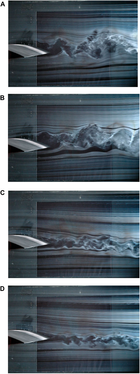
Figure 6. Flow visualization in near wake of the airfoil and investigating the effect of different momentum coefficients on the changes in the flow structure under the influence of unsteady excitation, (A) basic model Cμ = 0, (B) Cμ = 0.12%, (C) Cμ = 0.34%, (D) Cμ = 3.72% (Feero et al., 2015).
Munday and Taira (2018) utilized the modified momentum coefficient parameter as a metric to assess the effectiveness of flow control. Their study focused on numerically investigating the impact of momentum injection on mitigating flow separation on a NACA 0012 airfoil operating at an angle of attack of 9° and Reynolds number of Re = 2.3 × 10⁴. Under these conditions, the airfoil experienced a significant separation, resulting in the detachment of the shear layer from the leading edge and the formation of large spanwise vortices. The breakdown of these vortices resulted in the generation of turbulent flow downstream. In this study, momentum is incorporated into the separated flow in two distinct forms through the use of swirling jets: wall-normal momentum and angular momentum. The investigation and analysis have focused on assessing the effects of different combinations of actuator inputs on the flow field and surface vorticity fluxes. The experiments revealed that the injection of wall-normal momentum resulted in a reduction in flow separation. Furthermore, the addition of angular momentum injection, in conjunction with wall-normal momentum injection, led to an enhanced reduction in flow separation. Accordingly, the modified momentum coefficient, as defined in Equation 8, was employed in this article. In this context, the correction function S, as described in Equation 9, represents the ratio of the velocity in the angular momentum mode
In the investigation conducted by Munday and Taira (2018), the responses of the flowfield and the surface vorticity fluxes to a range of actuation input combinations were examined in detail in order to evaluate the value of the modified momentum coefficient S. An illustrative example of the research findings is presented in Figure 7. The results illustrate the effectiveness of combining wall-normal and angular momentum in controlling flow separation and eliminating it along the suction surface of the airfoil. Figure 7 depicts the lift and drag forces as a function of Cμ*. Moreover, this figure presents time-averaged flow visualisations utilizing the time-averaged zero streamwise velocity ūx = 0 isosurface, colored with spanwise Reynolds stress τxy. In Figure 7, three broad classifications of flow can be identified with different colors. These categories include separated flow for Cμ* ≤ 1.5%, transitional flow for 1.5% < Cμ* ≤ 2%, and reattached flow for 2% < Cμ*. For low values of Cμ* ≤ 1.5%, as shown by the blue region in Figure 7, the flow remains separated and the time-averaged recirculation region has approximately the same size as in the baseline case. The control injection modifies the shear layer around the leading edge, yet this is insufficient to achieve reattachment. Conversely, values of Cμ* ≤ 1.5% result in a detrimental impact on the flow, leading to a decrease in lift in comparison to the baseline case (as indicated by the dashed lines). The second region, indicated in green in Figure 7, depicts transitional flow cases for 1.5% < Cμ* ≤ 2%, wherein the lift and drag coefficients exhibit a notable increase and decrease, respectively. In this region, the control input modifies the separated flow, which remains separated behind the actuators. Variations in the modified momentum coefficient between 1.5% < Cμ* ≤ 2% show different effects on the flow and lift. The variation of lift and drag in this region illustrates that the flow becomes sensitive to changes in the control input within transitional region. The third region, defined by the modified momentum coefficient of 2% < Cμ*, is represented by the yellow area in Figure 7. In this region, the controlled flow downstream of the actuators is reattached. This results in enhanced aerodynamic performance. Furthermore, the greatest enhancements in lift and reductions in drag are observed in this region, which is characterized by reattachment. However, it is important to note that excessively high values of S should be avoided; for cases where S > 1.5%, a significant increase in the lift coefficient is observed, but it is accompanied by unstable behavior due to dynamic stall.
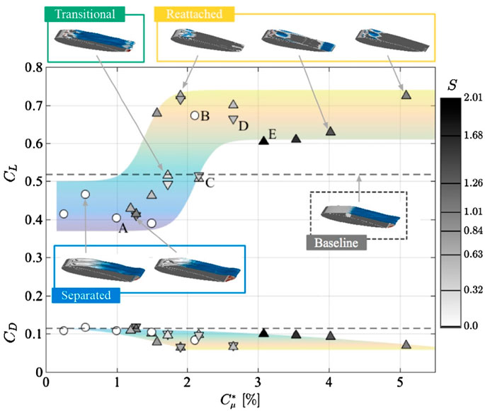
Figure 7. The effect of modified momentum coefficient on lift (top) and drag (bottom) coefficients. Values without flow control are indicated by dashed lines. Controlled cases include: injection of wall-normal momentum with pure blowing (○), injection of angular momentum with corotating (∇) and injection of angular momentum with counter-rotating (Δ) (Munday and Taira, 2018).
2.2 Dimensionless frequency or reduced frequency F+
One of the crucial design parameters for the control actuator in situations involving unsteady oscillatory or pulsed excitations is the excitation frequency. Numerous studies have represented the excitation frequency as the dimensionless frequency F+, which is defined in a manner similar to the Strouhal number, as shown in Equation 10.
The dimensionless frequency serves to adjust the physical time scale of the excitation, whereby the excitation frequency f is made dimensionless by incorporating the characteristic velocity uref and length scale lref. Typically, the incidence velocity or freestream velocity is considered as the characteristic velocity uref. In the case of airfoils, the length scale lref is defined as the length of the airfoil chord. Some studies have determined the length scale lref for calculating F+ based on the length of the separation region. In the context of an airfoil, when separation occurs at the leading edge, the length scale lref is equal in both cases, and selecting the chord length of the airfoil facilitates comparison with other experimental results.
To achieve optimal flow separation control, experiments have identified different dimensionless frequency bands F+ as the most effective values, depending on the underlying physical mechanism of flow control. For improved performance of the control system, when the excitation amplitude reaches a threshold value, the actuator should operate at an appropriate excitation frequency. The unsteady actuator produces varying effects on the flow depending on the time scale and frequency of excitation.
A comprehensive analysis of airfoil flow control studies conducted by Greenblatt and Wygnanski (Greenblatt and Wygnanski, 2000; Wygnanski, 2000) reveals that, in the majority of cases, the optimal dimensionless frequency F+ for controlling flow separation in poststall conditions falls within the range of 0.3 ≤ F+ ≤ 4. Their findings also indicate that this range applies to excited shear layer and deflected flap. However, alternative research, particularly the work of Glezer et al. (Smith et al., 1998; Amitay et al., 2024), suggests that higher magnitude dimensionless frequencies, such as F+ = 10 or 20, can also effectively control separated flow. The wide range of effective frequencies in flow separation control can be attributed to factors such as surface curvature, upstream conditions, boundary layer conditions, excitation methods, and the utilization of different momentum coefficient values (Cμ > Cμ,min) (Greenblatt and Wygnanski, 2003). Seifert et al. conducted experiments to examine the impact of dimensionless frequency F+ on the increase in lift coefficient for a NACA 0015 flapped airfoil across a wide range of Reynolds numbers and two different excitation locations (Seifert et al., 1996). The results of their research are presented in Figure 8. One case depicted in the figure pertains to airfoil tests at angles of attack ranging from 16° to 22° in the poststall regime, conducted at the leading edge of the excitation. The second experiment involves testing the airfoil at a zero angle of attack and a deflection flap angle of 20°. In this case, the control actuation is carried out on the shoulder of the flap. The figure demonstrates that, for both experiments, the effective excitation frequency for this airfoil falls within the range of 0.5 ≤ F+ ≤ 1. Another study (Seifert and Pack, 1999) also concluded that the effective excitation frequency for high Reynolds number flow lies within the range of 0.5 ≤ F+ ≤ 1. Furthermore, the research conducted by Hecklau et al. (Hecklau et al., 2011; Hecklau et al., 2013) indicates that in scenarios where large-scale disturbances directly transport high-momentum fluid within the boundary layer in low Reynolds flow, the minimum excitation frequency required to prevent the onset of flow separation between each controlled pulse is approximately F+ ≈ 0.5.
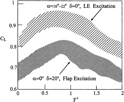
Figure 8. The lift response of a NACA 0015 airfoil to periodic excitation at either the leading edge or flap shoulder at different frequencies for Cμ = 0.08% and 1.5 × 10⁵ ≤ Re ≤ 6 × 10⁵ (Seifert et al., 1996).
The effectiveness of separation control typically relies on the receptivity of the mean flow to the external excitation. In this technique, the characteristic timescale of flow physics and its instabilities play a significant role. Previous research has demonstrated that enhancing flow instabilities can be an effective approach to control separation (Wu et al., 1998). When dealing with a separated flow, the excitation frequency can be adjusted based on the frequency of natural instabilities in the shear layer. Consequently, disturbances introduced by the active flow control system within the medium range have undergone by maximum amplification until they reach the model’s trailing edge, therefore providing the highest mixing rate. As a result, the mixing rate along the shear layer experiences a substantial increase, leading to the highest mixing ratio (Wygnanski, 2000). In this technique, a greater amount of momentum is transferred to the flow near the surface.
Several studies (Wu et al., 1998; Kotapati et al., 2010; Mccullough and Gault, 1951; Chang, 1976), provide a comprehensive analysis of the natural frequencies of flow on an airfoil, which play a crucial role in determining the excitation frequency. For flow over a thin airfoil at a certain Reynolds number, three natural frequencies can be observed depending on the angle of attack. At a low angle of attack, the flow over the airfoil remains attached to the surface despite an adverse pressure gradient. Consequently, the dominant phenomenon in the flow is wake instability, and the frequency of these instabilities can be referred to as the wake frequency fwake. As the angle of attack increases, separation may occur near the leading edge due to the adverse pressure gradient. However, the separated shear layer may reattach before reaching the trailing edge. In such cases, three natural frequencies are present: the roll-up frequency of vortices in the shear layer fsl, the frequency of fluctuations caused by unsteady flow in the separation bubble fsep, and the frequency of fluctuations caused by unsteady flow in the wake fwake. At high angles of attack, where separation is significant and post-stall flow dominates, the flow behaves similarly to passing through a bluff body. In post-stall conditions, two primary instabilities are observed: the roll-up of vortices in the separated shear layer fsl and the release of large-scale vortices in the wake fwake and the fluctuations caused by the unsteady flow (Wu et al., 1998). These instabilities typically correspond to dimensionless frequencies fsl+ ≈ 10 (Boutilier and Yarusevych, 2012a; Boutilier and Yarusevych, 2012b) and fwake+ ≈ 1 (Buchmann et al., 2013), respectively. Here, the dimensionless frequency is defined as f+ = fc/U∞, where f is the frequency of instability in separated flow and c is the chord length.
The reported effective dimensionless frequency band is largely limited to F+ = O (1) in cases where the control mechanism relies on the resonance of inherent perturbations in flow instabilities. For example, exciting the separated shear layer at frequencies close to F+ = 1, taking advantage of the wake instability with a frequency of fwake+ ≈ 1 (representing the frequency of shedding of large-scale vortical structures into the wake) has proven to be effective. In the excitation mode with frequency F+ = O (1), large vortical structures are formed, which are subsequently transferred downstream near the airfoil surface. This process induces unsteady reattachment and time-periodic variation in the flow circulation on the airfoil (Amitay and Glezer, 2002a; Amitay and Glezer, 2002b). The study conducted by Amitay and Glezer (2002b) examined the impact of separation control across a broad range of F+. However, in this particular research, the frequency range of separated flow during stall conditions was not explicitly defined. Therefore, results have not been identified when the control mechanism targets flow instabilities.
Yarusevych and Kotsonis (2017) investigated the effect of controlling the separation bubble phenomenon on a NACA 0012 airfoil for flow with Reynolds number Re = 1.3 × 10⁵, in actuation frequencies 2 ≤ F+ ≤ 10 and F+ = 100. The results of this study demonstrated that the most significant reduction in the size of the separation bubble was achieved at the excitation frequency of F+ = 6, which corresponds to enhanced fluctuations of the separated shear layer. Wu et al. (1998) conducted two-dimensional simulations on a NACA-0012 airfoil in turbulent flow under post-stall conditions, with a Reynolds number of 5 × 10⁵ and angles of attack ranging from 18° to 35°. Wu et al. (1991) put forth the idea that the fundamental principle behind the post-stall lift enhancement due to unsteady controls involves a series of interconnected mechanisms: vortex layer instability, receptivity, resonance, and nonlinear streaming. The diverse response spectrum of the shear layer to disturbances leads to varying resonant states when exposed to different actuation frequencies. These different resonant states play a crucial role in determining the lift and drag characteristics of the object. Their findings revealed that the effective dimensionless frequency F+ is in the range of 0.3–2.0 times the frequency of the wake (0.3–2.0 fwake). Specifically, when the excitation frequency was set at one and two times the natural frequency of the wake (f/fwake = 1.0, 2.0), the lift-to-drag ratio increased by 49.2% and 46.7%, respectively, at an angle of attack of 25°, where harmonic resonance of vortex shedding occurred. Notably, the maximum lift increase observed in these experiments was 73.2%, which was achieved in the subharmonic resonance at half the natural frequency of vortex shedding in the wake (f/fwake = 0.5).
In a separate study (Duvigneau and Visonneau, 2006), researchers simulated the two-dimensional flow over a NACA-0015 airfoil at Re = 8.96 × 10⁵ and angles of attack ranging from 12° to 24°. They proposed an optimization method to maximize the lift coefficient at various angles of attack by modifying the design parameters, including the excitation frequency, velocity ratio, pitch angle. Their research indicated that the optimal dimensionless frequency F+ was approximately 0.8 for angles of attack between 14° and 20°, while a much smaller value of F+ = 0.25 was obtained for an angle of attack of 22°. They concluded that the optimal average lift is achieved at F+ = 0.85 across the entire range of angle of attack variations. A similar study was conducted by You and Moin (2008) using the LES method for an angle of attack of 16.6°. It was concluded that applying control excitation with a dimensionless frequency of F+ = 1.284 resulted in a 70% increase in lift. Experimental studies have also been conducted on flow separation control on the NACA-0015 airfoil (Buchmann et al., 2013; Tuck and Soria, 2008) at a Reynolds number of 3 × 10⁴ and an angle of attack of 18°. The results of this research indicated that the optimal excitation frequencies for achieving maximum lift were F+ = 0.65 and F+ = 1.3, which correspond to the wake frequency fwake and its harmonic 2fwake, respectively. Other studies have reported the optimal frequencies for an unsteady control system to reattach the flow to the deflected flap surface as F+ ≈ 1.5 (Darabi and Wyganski, 2004) and F+ ≈ 1.3 (Nishri and Wygnanski, 1998).
In situations where the flow on the airfoil experiences separation near the leading edge, the application of an appropriate control method can facilitate the reattachment of the separated flow to the surface. At the optimum frequency, the flow reattaches to the surface with the lowest momentum coefficient Cµ. The optimum frequency for the reattachment of the flow to a straight surface occurs at dimensionless frequency of F+ = 1. Once the flow is reattached due to the effective operation of the control system, it forms a large bubble. The size of this bubble may decrease as the frequency increases. Injecting flow with a frequency higher than the natural frequencies of the flow primarily enhances the turbulent kinetic energy of the boundary layer by introducing small-scale vortical structures (Zander and Nitsche, 2013). However, injecting flow at excessively high frequencies leads to flow separation at the trailing edge, as the dimensionless frequency F+ becomes so high that the applied fluctuations are dissipated before reaching the flap’s trailing edge. Therefore, the excitation frequency must be sufficiently high to prevent flow separation from the surface between two consecutive pulses (Hecklau et al., 2011). Previous studies indicate that in cases where there is a separated flow with reattachment to the surface, the most effective frequency range shifts to higher values within the range of 3 < F+ < 4 in order to avoid flow re-separation (Nishri and Wygnanski, 1998).
Raju et al. (2008) conducted a numerical simulation of the NACA-4418 airfoil at a Reynolds number of 4 × 10⁴ and an angle of attack of 18°. In the absence of control, the flow over the airfoil exhibits a separation bubble near the leading edge, leading to stall. Under these conditions, the uncontrolled flow is characterized by three natural frequencies: the shear layer frequency fsl, the separation bubble frequency fsep, and the wake frequency fwake. The simulation results indicate that applying synthetic jet excitation near the frequency of oscillations caused by the unsteady flow in the separation bubble fsep+∼ O (1) (based on chord length) effectively reduces the size of the separation bubble and improves the lift-to-drag ratio. However, employing a higher excitation frequency, on the order of magnitude of the roll-up of vortices in the shear layer fsl+ ∼ O (10) (based on chord length), for controlling the separation is not beneficial. This is because in such cases, the vortices in the shear layer merge into a larger vortex, intensifying the separation phenomenon. The occurrence of inefficient excitation at high frequencies, resulting from the merging of Kelvin-Helmholtz vortices, has been observed by Kotapati et al. (2010) in the context of flow over a flat plate with an elliptical leading edge and a blunt trailing edge.
However, contrasting findings were reported by Amitay et al. (2001) based on their experimental results. The results demonstrate the presence of two distinct regimes of dimensionless frequency that lead to an elevation in the lift to pressure drag ratio as shown in Figure 9. The first regime occurs when the excitation frequency equals with the frequency of large-scale vortex shedding in the wake fwake, falling within the range of F+ ≤ 4. The second regime occurs when the excitation frequency surpasses the frequency of vortex shedding in the wake fwake by one or more orders of magnitude, specifically within the range of F+ ≥ 10.
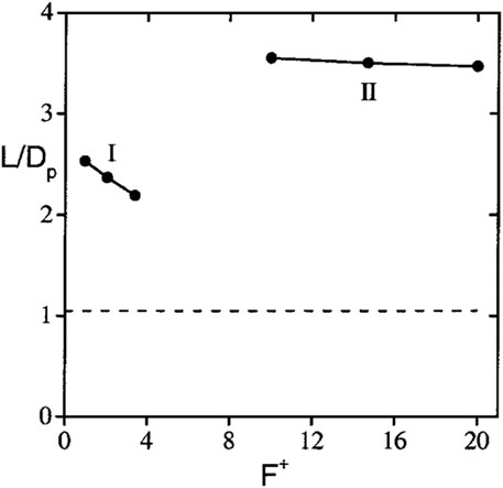
Figure 9. Variation of the lift to pressure drag ratio with F+, uncontrolled value shown as dashed line (Amitay et al., 2001).
Glezer et al. (2005) demonstrated that excitation at low frequencies within the range of the natural shedding frequency, and excitation at high frequencies, at least an order of magnitude higher than the frequency of natural instabilities, yield distinct effects on the shear layer. The separated flow on the airfoil before excitation is shown in Figures 12A. When the excitation frequencies approach the natural vortex shedding frequency, the separated shear layer undergoes deflection towards the surface. At this time, a sequence of vortices can be observed that are advected downstream along the airfoil surface. These vortices persist up to the trailing edge of the airfoil, and their strength increases as they move downstream due to the potential coupling between the excitation frequency and the natural shedding frequency of the vortices in the flow (Figures 10, 11, 12B–E) (Glezer et al., 2005; Abdolahipour, 2023; Zhang and Ravi, 2015).
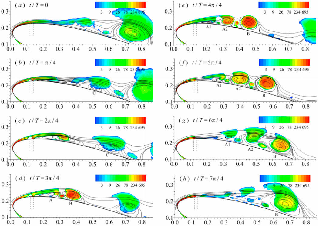
Figure 10. Evolutions of phase-averaged streamlines and Q criteria for excitation case with F+ = 0.5. The vertical dotted line shows the location of the actuator (Zhang and Ravi, 2015).
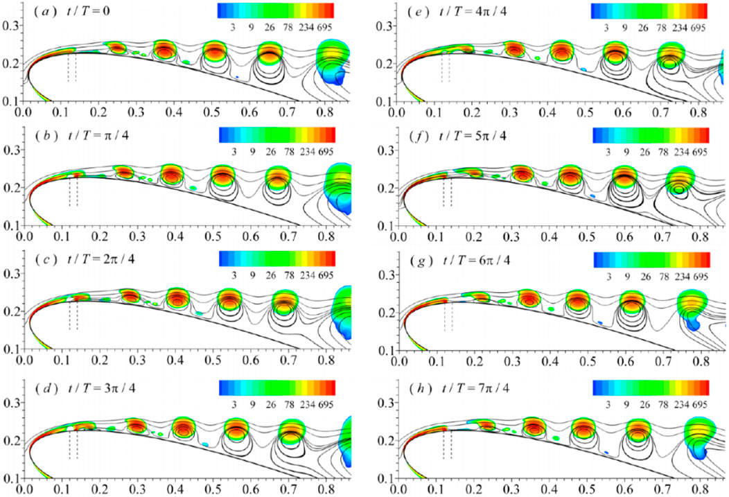
Figure 11. Evolutions of phase-averaged streamlines and Q criteria for excitation case with F+ = 4. The vertical dotted line shows the location of the actuator (Zhang and Ravi, 2015).
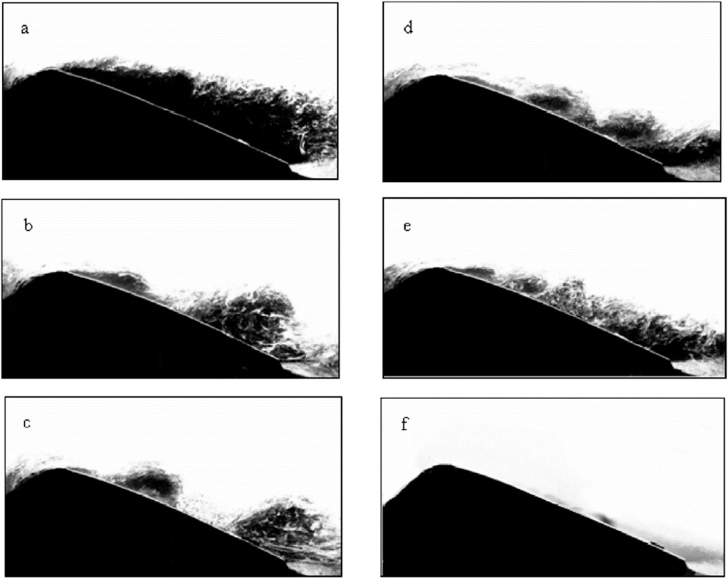
Figure 12. Visualization of the phase averaged flow on the airfoil surface at the angle of attack of 15°: (A) basic model and controlled model with dimensionless frequency F+ = (B) 0.7, (C) 1.1, (D) 2.05, (E) 3.3, and (F) 10 (Glezer et al., 2005).
On the other hand, at dimensionless frequencies at least an order of magnitude higher than the natural frequency, the flow remains completely attached to the airfoil surface, with no discernible presence of large-scale coherent structures (Figures 12F) (Glezer et al., 2005; Abdolahipour, 2023; Zhang and Ravi, 2015). Glezer et al. (2005) have presented a different approach to controlling separation on lifting surfaces through high-frequency actuation. This approach underscores the fluidic modification of the aerodynamic shape of the surface, with the objective of altering the streamwise pressure gradient to achieve either partial or complete elimination of flow separation. Actuation is achieved through the establishment of an interaction domain between the actuation jet and the crossflow upstream of the separation, which can be viewed as a virtual alteration in surface shape. In this technique, the characteristic wavelength of excitation is at least an order of magnitude smaller than the corresponding length scale in the flow. Moreover, the excitation frequency is sufficiently high to ensure that the interaction between the excitation and the crossflow remains essentially time-invariant on the global timescale of the flow. Overall, various experiments have demonstrated flow reattachment in stall conditions and improved airfoil performance for excitation frequencies at both the scale of F+ = O (1) and the larger scale of F+ = O (10) (Feero et al., 2015; Glezer, 2011).
Further investigation into the various aspects of these two control approaches in the flow field has revealed that low-frequency excitation induces separated shear-layer flow oscillations. These flow oscillations establish a robust coupling with the wake, resulting in significant oscillations of the separation point during each excitation cycle. Consequently, these oscillations give rise to unstable aerodynamic forces. On the other hand, when the excitation frequency reaches a sufficiently high level, a small interaction region forms upstream of the separation region, causing displacement of the passing flow. These alterations create a favorable local pressure gradient, leading to the formation of a thinner and more stable boundary layer downstream of the interaction region. Ultimately, these modifications result in a significant delay in flow separation. As depicted in Figure 13, low-frequency excitation results in significant fluctuations in circulation, consequently causing fluctuations in aerodynamic forces. Conversely, when high-frequency excitation is applied, circulation undergoes a brief transition period before reaching a quasi-steady state. Consequently, the aerodynamic forces generated in this state exhibit relatively time invariant (Abdolahipour, 2023). These findings highlight a fundamental distinction between low-frequency and high-frequency excitation approaches. In the case of high-frequency excitation, the excitation becomes decoupled from the unsteady frequencies of the base flow. As a result, the resulting aerodynamic forces remain practically time invariant on a scale that is comparable to the characteristic timescale of the base flow, and overall flow fluctuations are attenuated, and possibly even damped.
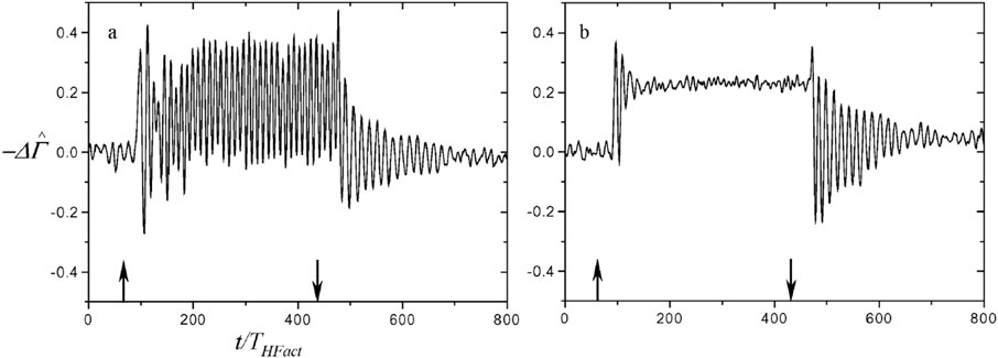
Figure 13. The increase in phase-averaged circulation under the influence of excitation by the control actuator with the excitation frequency a) F+ = 0.24 b) F+ = 2.5 (Time is dimensionless based on the period of THFact. The arrows show the time when the actuator is turned on and off) (Glezer et al., 2005).
In recent research (Abdolahipour et al., 2022a; Abdolahipour et al., 2022b; Abdolahipour et al., 2021), a novel method has been employed to take advantage of the benefits of both low and high excitation frequencies using a vortex generator jet actuator (VGJ). This method involves modifying the waveform of the excitation signal through the introduction of burst modulation. In the literature, burst modulation of an actuator signal refers to the controlled switching on and off of the actuator for predetermined periods. In this study, the burst modulated signal is achieved by combining two square-wave signals: a high-frequency square-wave containing the base frequency fc and a low-frequency square-wave containing the burst frequency fm, called carrier signal and modulating signal, respectively. Figure 14 illustrates the schematic representation of the signal burst modulation. This combination enables the incorporation of both high and low excitation frequencies within a single actuator driving signal. For instance, it becomes possible to simultaneously set the frequency of flow shear layer instability, wake instability, or a frequency at least an order of magnitude larger within one excitation signal. In the context of flow control, both high and low frequencies can approximately correspond to the first-subharmonic, harmonic, and first-superharmonic of the natural vortex shedding frequency in the uncontrolled flow.
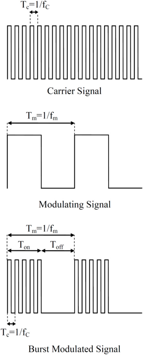
Figure 14. Schematic of the signal burst modulation (Abdolahipour et al., 2022b).
A noteworthy attribute of this signal modulation method for the generation of modulated pulse jet MPJ is its capacity to reduce air consumption by approximately 50% in comparison to a simple pulsed jet SPJ over a specific portion of the flow control period, while still producing equivalent or even greater control benefits, as illustrated in Figure 15.
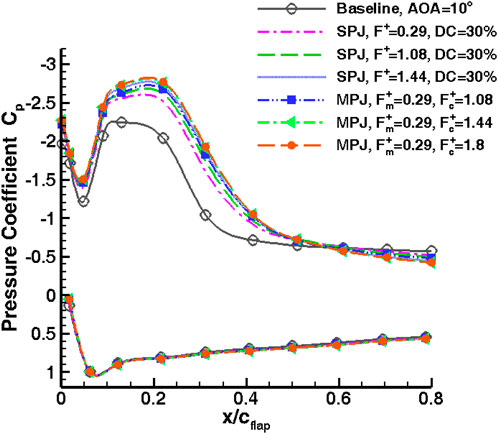
Figure 15. Pressure distribution on the flap surface with SPJ and MPJ actuation at AOA = 10° (Abdolahipour et al., 2022a).
The optimal excitation frequency is also influenced by the excitation location. The location of the excitation itself is a crucial parameter in designing an active flow separation control system. Previous research has generally indicated that excitation is most effective when the actuator location is positioned upstream of the separation point. However, there is no specific recommendation for the most effective actuator location. The findings of Amitay and Glezer (2002b) highlight the complexity of the problem when the excitation frequency is introduced as a variable. They used a special configuration that allowed the azimuthal position of the jet to be continuously changed relative to the airfoil chord. Their results demonstrate that if the actuator is positioned at the highest possible location on the airfoil, the excitation applied at the dimensionless frequencies of F+ = 3.3 and 10, equivalent to the excitation frequency f = 246 and 740 Hz, has no measurable impact on the pressure distribution on the airfoil and does not prevent separation. Conversely, under the same conditions, excitation at the dimensionless frequency of F+ = 0.95, equivalent to the frequency f = 71 Hz, leads to flow reattachment and the formation of a separation bubble on the airfoil surface. By changing the location of actuation to x/c = 0.011, the dimensionless frequencies of F+ = 3.3 and 10 result in a partial reattachment. Actuation with F+ = 0.95 at this particular location results in a significant increase in suction pressure followed by complete reattachment of the flow.
Amitay and Glezer (2002b) have highlighted the significant impact that different excitation methods can have on the results obtained. For instance, when fe ≤ 300 Hz, internally mounted acoustic speakers were employed to generate uniform jets in the span direction. However, for fe ≥ 300 Hz, the performance of these speakers diminishes, both in the presence and absence of cross flow. In fact, in the presence of crossflow, the jet velocity decreases by over 80%, leading to a substantial reduction in the overall efficiency of the control system. Consequently, for high frequencies fe ≥ 300 Hz, a flow injection actuator with a small cavity was utilized.
2.3 Threshold variation of momentum coefficient and aerodynamic efficiency with excitation frequency and location
The remaining question pertains to how the threshold coefficient of momentum and aerodynamic efficiency, in terms of both lift and drag, are influenced by excitation frequency and relative slot location. To address this inquiry, a novel experimental study (Feero et al., 2017) was conducted. The research focused on investigating post-stall separated flow reattachment on a NACA 0025 airfoil at Re = 1 × 10⁵ and an angle of attack of 12° using synthetic jet flow control. One of the objectives of this study was to examine the impact of control parameters, specifically the momentum coefficient and excitation frequency, with varying values of F+ = 1, 2, 14, and 58, on the wing’s aerodynamic performance. The findings indicate that excitation at the frequency corresponding to wake instabilities fwake yields the greatest lift increase, while excitation at frequencies of a higher order of magnitude within the separated shear layer instabilities range fsl results in maximum drag reduction. Consequently, an excitation frequency of F+ = 1 (f+wake) is more suitable when seeking lift enhancement, whereas F+ = 14 (f+sl) is more appropriate for achieving the maximum lift-to-drag ratio. Furthermore, an increase in the blowing ratio or momentum coefficient positively impacts both lift and drag coefficients across all frequencies, up to a certain saturation value. This saturation value is dependent on the excitation frequency F+ and the location of the actuator (Feero et al., 2017).
As depicted in Figure 16, the number of structures during one cycle exhibits an increase with F+ up to a certain threshold. To achieve a greater number of vortices within a spatial domain, the size of the structures needs to be reduced, which can be accomplished by reducing the injection time. At F+ = 1, it is evident that a single vortex moves downstream and away from the surface throughout one pulsed excitation cycle. During a portion of the pulse cycle, two such vortices are present on the airfoil surface. In contrast, at F+ = 6, a larger number of relatively smaller vortices that remain in closer proximity to the airfoil surface are observed. This reduction in vortex size and their path along the airfoil surface leads to a narrower wake and consequently less drag as shown in Figure 17.
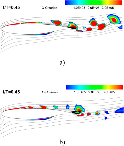
Figure 16. The streamlines and Q-criterion for the actuated case at AOA = 16° and at time instant t/T = 0.45 of one actuation cycle (A) F+ = 1, (B) F+ = 6 (Abdolahipour, 2023).
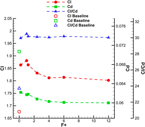
Figure 17. Variation of time-averaged aerodynamic forces for different actuation frequencies at AOA = 16° (Abdolahipour, 2023).
In a study conducted by Feero et al. (2015), the impact of excitation frequency and momentum coefficient on reattachment and subsequent drag reduction was investigated using synthetic jet actuation. Here, the dimensionless frequency expressed as a Strouhal number St = fc/U∞, where f is the frequency of excitation and c is the chord length. Figure 18A presents a comparison of the drag coefficient CD changes with the momentum coefficient Cμ for three excitation frequencies. At a dimensionless modulation frequency of Stm = 0.84, an initial increase in drag coefficient is observed due to the vortex shedding at the scale of the dominant separated wake frequency. By increasing the momentum coefficient to 0.12%, the threshold momentum coefficient required for reattachment is reached at the excitation mode of Stm = 0.84, resulting in a 30% reduction in the drag coefficient. For Ste = 58, a threshold value of Cμ was reached at 0.34%, resulting in a narrowing and downward shift of the wake, accompanied by a decrease in CD of approximately 45%. These changes corresponded to the steady reattachment of the boundary layer to the airfoil surface. At Cμ = 0.34%, all three excitation frequencies yield the lowest drag coefficient CD. For a high momentum coefficient Cμ, the excitation at dimensionless frequency Ste = 58 performs slightly better. Notably, the results indicate that the momentum coefficient Cμ required for maximum drag reduction is independent of the excitation frequency. One potential explanation for the observed common maximum drag reduction for all excitation frequencis may be inferred from the unsteady blowing ratio
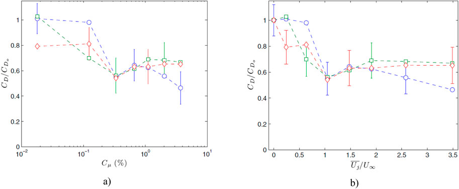
Figure 18. Drag coefficient as a function of (A) momentum coefficient Cμ (B)
Figure 19 illustrates the effect of frequency and momentum coefficient of pulsed excitation on the lift coefficient of a NACA 0015 airfoil. The experiment involved applying pulsed excitation at the leading edge of the airfoil under post-stall conditions (AOA = 16°) at Reynolds numbers Re ≤ 6 × 10⁵. At a momentum coefficient of Cμ = 0.2%, it appears that high-frequency excitation within the range of 2 ≤ F+ ≤ 11 has minimal effect on the lift coefficient. The peak effectiveness is within the range of 0.5 ≤ F+ ≤ 1. As expected, at a higher momentum coefficient of Cμ = 1.2%, the effective frequency range expands to approximately 0.5 ≤ F+ ≤ 3. This is due to the reduction in hysteresis at the most effective dimensionless frequency F+, which helps to prevent separation and promote flow reattachment (Seifert and Pack, 1999). Furthermore, it is important to highlight that even with six times more momentum input, there was no significant increase in the lift coefficient at the most effective dimensionless frequency F+.
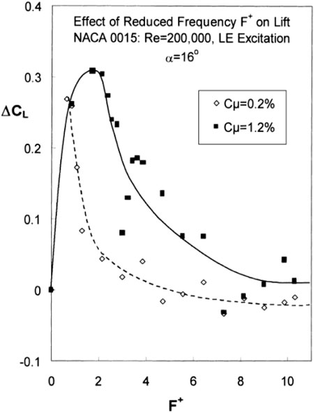
Figure 19. The effect of dimensionless frequency with different momentum coefficients on post-stall lift (Greenblatt et al., 1999).
Table 1 presents a summary of the optimum controlling factors or parameters and the most significant airfoil performance improvements relative to the baseline, taking into account the airfoil type and Reynolds number. Additionally, a summary of selected experimental and numerical investigations dealing with active separation control applied to an airfoil model using instability exploitation, is presented in Table 2. This table summarizes the frequencies associated with the instabilities present in the uncontrolled flow, fsl and fwake, were determined by flow characteristic measurements in the separated shear layer and wake. In these investigations, both high and low excitation frequencies approximately correspond to the subharmonic, harmonic, and superharmonic of the natural instabilities frequencies in the uncontrolled flow. All authors report a beneficial effect of the control approach, but the magnitude of the benefit varies considerably between studies. Values marked (*) were calculated based on the provided context.
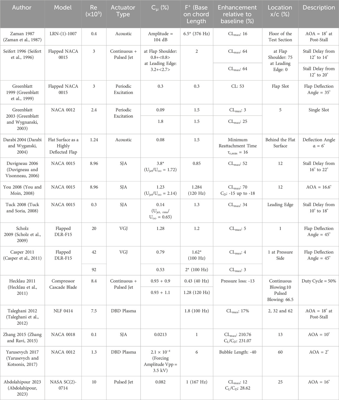
Table 1. Representative summary of experimental and numerical investigations on active separation control by unsteady excitation.
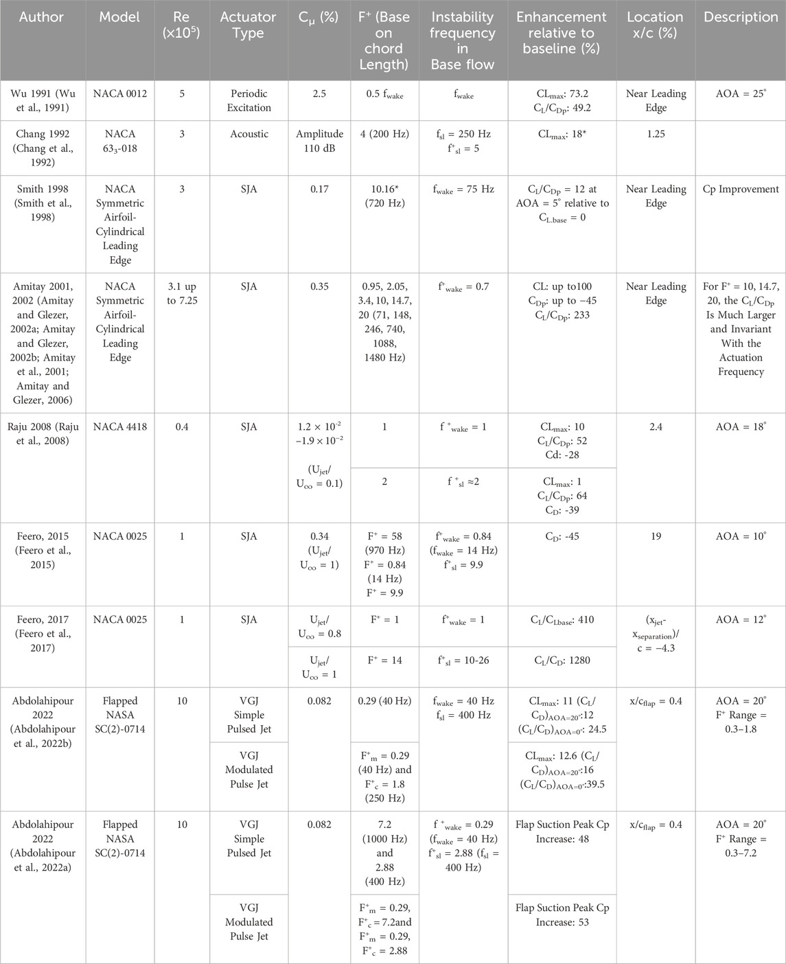
Table 2. Representative summary of experimental and numerical investigations on active separation control by unsteady excitation using instability exploitation.
The data presented in Tables 1, 2 indicate that the dimensionless frequency range of 0.8 ≤ F+ ≤ 2 is identified as the optimal frequency for enhancing aerodynamic efficiency in 76% of the research studies detailed in these tables. The analysis of the data presented in Table 2 reveals that employing an excitation frequency proximate to the wake instabilities frequency fwake demonstrates enhanced effectiveness in lift improvement. Conversely, utilizing an excitation frequency near the frequencies within the range of separated shear layer instabilities fsl leads to drag reduction and the optimization of the lift-to-drag ratio. Furthermore, elevating the blowing ratio or momentum coefficient exerts a beneficial impact on both lift and drag coefficients across all frequencies, up to a defined saturation threshold.
3 Conclusion
The review presented in this paper outlined the effect of two crucial parameters in separation control by means of unsteady excitation. Among different methods, the application of unsteady excitation locally at the lifting surfaces has demonstrated the most potential as an efficient and practical means of separation control. Reviewing the literature reveals that the utilization of unsteady excitation to control flow separation is of significant interest across various applications. In this paper, an attempt was made to identify the optimal ranges of momentum coefficient and excitation frequency for achieving flow reattachment and separation delay in a shear layer flow on the lifting surfaces by means of different unsteady excitation techniques such as pulsed jets, synthetic jets, plasma, and acoustic actuators. It is important to note that the determination of the effective or optimal excitation frequency is case-dependent and relies on factors such as the actuation location, geometry of lifting surfaces, angle of attack and other freestream flow parameters. Therefore, the selection of the appropriate excitation frequency should be based on a thorough understanding of the uncontrolled flow physics in each specific case.
The research findings indicate that, elevating the amplitude or momentum coefficient of actuation exerts a beneficial impact on the aerodynamic characteristics of lifting surfaces across all frequencies, up to a defined saturation threshold. However, for flow reattachment and separation delay, there exists a saturation point where the benefits of flow control become limited once a specific momentum coefficient is reached. In other words, once a threshold momentum coefficient is achieved, further increases in momentum input have minimal impact on the attached flow.
Regarding excitation frequency, the literature primarily focuses on two distinct frequency bands. The first band corresponds to the dominant natural shedding frequencies, while the second band encompasses frequencies at least an order of magnitude higher than the natural instabilities frequencies. Several studies have shown that excitation at a dimensionless frequency in the range of F+ = 1 has a positive effect on reducing flow separation and increasing lift. However, recent studies have contradicted this finding by suggesting that dimensionless frequencies an order of magnitude higher than the natural shedding frequency yield better results. One noteworthy discovery in these studies is the fundamental distinction between low-frequency and high-frequency actuation approaches. Low-frequency actuation induces pronounced oscillations in the aerodynamic forces on lifting surfaces, whereas high-frequency actuation generates time-invariant aerodynamic forces. In fact, actuating at high frequencies has been discovered to result in a more stable flow reattachment and produce better aerodynamic properties when compared to using low-frequency control methods. Recently, the excitation frequency modulation technique has emerged as a means to take advantage of both high and low excitation frequencies. A notable feature of the signal modulation was that this method can reduce the air consumption by half the amount consumed by a simple pulsed jet over a certain part of the flow control period, producing the same amount of control benefits or even more.
In this context, new research horizons are suggested for future research. The present review paper primarily focuses on studies that mainly consider the optimization of one parameter such as the efficiency of flow separation control, and lift enhancement. However, future investigations could consider multi-objective optimization, taking into account all performance metrics such as drag reduction, lift enhancement, and energy consumption. This approach would provide a more comprehensive understanding of the trade-offs and potential synergies between different control parameters, leading to more efficient and practical flow separation control strategies.
While the present review paper examines both experimental and numerical studies, future research could focus on conducting more extensive experimental investigations to validate the findings and explore practical applications. The experiments on scaled models or full-scale prototypes can provide valuable insights into the effectiveness of different excitation frequencies and momentum coefficients in flow separation control techniques, facilitating their implementation in practical engineering applications. While the current review paper examines periodic excitation and momentum injection as active flow control techniques such as synthetic jets, pulsed jets, and plasma actuators, future investigations could explore the effectiveness of other control strategies, such as sweeping jet actuators or adaptive control algorithms. Comparing the performance of these strategies can help identify more efficient and reliable approaches for separation control. In addition to excitation frequency and momentum coefficient, the surface characteristics of lifting surfaces can also play a crucial role in flow separation control. Future research could focus on studying the effects of surface modifications, such as compliant coatings, on the efficiency of unsteady flow separation control. Understanding how these surface modifications interact with excitation frequency and momentum coefficient can provide valuable insights into optimizing flow control techniques.
Author contributions
SA: Investigation, Methodology, Resources, Writing–original draft, Writing–review and editing.
Funding
The author(s) declare that no financial support was received for the research, authorship, and/or publication of this article.
Conflict of interest
The author declares that the research was conducted in the absence of any commercial or financial relationships that could be construed as a potential conflict of interest.
Publisher’s note
All claims expressed in this article are solely those of the authors and do not necessarily represent those of their affiliated organizations, or those of the publisher, the editors and the reviewers. Any product that may be evaluated in this article, or claim that may be made by its manufacturer, is not guaranteed or endorsed by the publisher.
References
Abdolahipour, S. (2023). Effects of low and high frequency actuation on aerodynamic performance of a supercritical airfoil. Front. Mech. Eng. 9, 1290074. doi:10.3389/fmech.2023.1290074
Abdolahipour, S., Mani, M., and Arash, S. T. (2022b). Experimental investigation of flow control on a high-lift wing using modulated pulse jet vortex generator. J. Aerosp. Eng. 35 (5), 05022001. doi:10.1061/(asce)as.1943-5525.0001463
Abdolahipour, S., Mani, M., and Shams Taleghani, A. (2021). Parametric study of a frequency-modulated pulse jet by measurements of flow characteristics. Phys. Scr. 96 (12), 125012. doi:10.1088/1402-4896/ac2bdf
Abdolahipour, S., Mani, M., and Shams Taleghani, A. (2022a). Pressure improvement on a supercritical high-lift wing using simple and modulated pulse jet vortex generator. Flow, Turbul. Combust. 109 (1), 65–100. doi:10.1007/s10494-022-00327-9
Amitay, M., and Glezer, A. (2002a). Controlled transients of flow reattachment over stalled airfoils. Int. J. Heat. Fluid Flow. 23 (5), 690–699. doi:10.1016/s0142-727x(02)00165-0
Amitay, M., and Glezer, A. (2002b). Role of actuation frequency in controlled flow reattachment over a stalled airfoil. AIAA J. 40 (2), 209–216. doi:10.2514/3.15052
Amitay, M., and Glezer, A. (2006). “Aerodynamic flow control using synthetic jet actuators,” in Control of fluid flow (Berlin, Heidelberg: Springer Berlin Heidelberg, 45–73. doi:10.1007/978-3-540-36085-8_2
Amitay, M., Smith, B., and Glezer, A. (1998). Aerodynamic flow control using synthetic jet technology. AIAA Pap. 98-0208, 36th Aerosp. Sci. Meet. Exhib. doi:10.2514/6.1998-208
Amitay, M., Smith, D. R., Kibens, V., Parekh, D. E., and Glezer, A. (2001). Aerodynamic flow control over an unconventional airfoil using synthetic jet actuators. AIAA J. 39 (3), 361–370. doi:10.2514/3.14740
Bauer, M., Peltzer, I., Nitsche, W., and G¨olling, B. (2010). Active flow control on an industry-relevant civil aircraft half model. Act. Flow Control II, Notes Numer. Fluid Mech. Multidiscip. Des. 108, 95–107. doi:10.1007/978-3-642-11735-0_7
Bernardini, C., Benton, S. I., Chen, J. P., and Bons, J. P. (2014). Pulsed jets laminar separation control using instability exploitation. AIAA J. 52 (1), 104–115. doi:10.2514/1.j052274
Betz, A. (1961). “History of boundary layer control in German,”. Boundary layer and flow control. Editor G. V. Lachmann (New York: Pergamon Press), 1, 1–20.
Boutilier, M. S., and Yarusevych, S. (2012a). Parametric study of separation and transition characteristics over an airfoil at low Reynolds numbers. Exp. Fluids 52 (6), 1491–1506. doi:10.1007/s00348-012-1270-z
Boutilier, M. S., and Yarusevych, S. (2012b). Separated shear layer transition over an airfoil at a low Reynolds number. Phys. Fluids 24 (8), 084–105. doi:10.1063/1.4744989
Buchmann, N., Atkinson, C., and Soria, J. (2013). Influence of ZNMF jet flow control on the spatio-temporal flow structure over a NACA-0015 airfoil. Exp. fluids 54 (3), 1485. doi:10.1007/s00348-013-1485-7
Casper, M., Scholz, P., Radespiel, R., Wild, J., and Ciobaca, V. (2011). “Separation control on a high-lift airfoil using vortex generator jets at high Reynolds numbers,” in 41st AIAA fluid dynamics conference and exhibit. Honolulu, Hawaii. No. AIAA 2011-3442.
Chang, R., Hsiao, F.-B., and Shyu, R.-N. (1992). Forcing level effects of internal acoustic excitation on the improvement of airfoil performance. J. Aircr. 29 (5), 823–829. doi:10.2514/3.46252
Cornish, J. J. (1953), “Prevention of turbulent separation by suction through a perforated surface,” Aerophysics Dept., Mississippi State Univ., Research Report No. 7.
Darabi, A., and Wyganski, I. (2004). Active management of naturally separated flow over a solid surface. Part 1. The forced reattachment process. J. Fluid Mech. 510 (7), 105–129. doi:10.1017/s0022112004009231
Du, H., Yang, L., Chen, S., Zhang, W., and Han, S. (2022). Effect of multistage circulation control on blade aerodynamic performance. Energies 15 (19), 7395. doi:10.3390/en15197395
Duvigneau, R., and Visonneau, M. (2006). Optimization of a synthetic jet actuator for aerodynamic stall control. Comput. and fluids 35 (6), 624–638. doi:10.1016/j.compfluid.2005.01.005
Feero, M. A., Goodfellow, S. D., Lavoie, P., and Sullivan, P. E. (2015). Flow reattachment using synthetic jet actuation on a low-Reynolds-number airfoil. AIAA J. 53 (7), 2005–2014. doi:10.2514/1.j053605
Feero, M. A., Lavoie, P., and Sullivan, P. E. (2017). Influence of synthetic jet location on active control of an airfoil at low Reynolds number. Exp. Fluids 58 (8), 99. doi:10.1007/s00348-017-2387-x
Fiedler, H. E., and Fernholz, H.-H. (1990). On management and control of turbulent shear flows. Prog. Aerosp. Sci. 27 (4), 305–387. doi:10.1016/0376-0421(90)90002-2
Flatt, J. (1961). “The history of boundary layer control research in the United States of America,” Boundary Layer and Flow Control. Editor G. V. Lachmann (New York: Pergamon Press) Vol. 1, 122–143.
Gad-el-Hak, M. (2006). Flow control: passive, active, and reactive flow management. New York, United States: Cambridge University Press.
Glezer, A. (2011). Some aspects of aerodynamic flow control using synthetic-jet actuation. Philosophical Trans. R. Soc. A Math. Phys. Eng. Sci. 369 (No.1940), 1476–1494. doi:10.1098/rsta.2010.0374
Glezer, A., Amitay, M., and Honohan, A. M. (2005). Aspects of low-and high-frequency actuation for aerodynamic flow control. AIAA J. 43 (7), 1501–1511. doi:10.2514/1.7411
Greenblatt, D., Darabi, A., Nishri, B., and Wygnanski, I. (1999). “Some factors affecting stall control with particular emphasis on dynamic stall,” in 30th AIAA fluid dynamics conference (Norfolk, VA: AIAA Paper), 99–3504.
Greenblatt, D., and Wygnanski, I. (2003). Effect of leading-edge curvature on airfoil separation control. J. Aircr. 40 (3), 473–481. doi:10.2514/2.3142
Greenblatt, D., and Wygnanski, I. J. (2000). The control of flow separation by periodic excitation. Prog. Aerosp. Sci. 36 (7), 487–545. doi:10.1016/s0376-0421(00)00008-7
Hecklau, M., Salazar, D. P., and Nitsche, W. (2013). “Influence of the actuator jet angle on the reattachment process with pulsed excitation,” in New results in numerical and experimental fluid mechanics VIII. Berlin: Springer, 143–150.
Hecklau, M., Wiederhold, O., Zander, V., King, R., Nitsche, W., Huppertz, A., et al. (2011). Active separation control with pulsed jets in a critically loaded compressor cascade. AIAA J. 49 (8), 1729–1739. doi:10.2514/1.j050931
Holman, R., Utturkar, Y., Mittal, R., Smith, B. L., and Cattafesta, L. (2005). Formation criterion for synthetic jets. AIAA J. 43 (10), 2110–2116. doi:10.2514/1.12033
Hunter, P. A., and Johnson, H. I. (1954). A flight investigation of the practical problems associated with porous-leading-edge suction. United States: NACA TN-3062.
Jones, G., and Englar, R. (2003). “Advances in pneumatic-controlled high-lift systems through pulsed blowing,” in 21st applied aerodynamics conference. Orlando, Florida. No. AIAA 2003-3411.
Jones, G., Yao, C.-S., and Allan, B. (2006). “Experimental investigation of a 2D supercritical circulation-control airfoil using particle image velocimetry,” in 3rd AIAA flow control conference, CA, 2006–3009.
Joslin, R. D., and Miller, D. N. (2009). Fundamentals and applications of modern flow control (American Institute of Aeronautics and Astronautics).
Knight, M., and Bamber, M. J. (1929). Wind tunnel tests on aerofoil boundary layer control using a backward opening slot. United States: NACA TN–323.
Kotapati, R. B., Mittal, R., Marxen, O., Ham, F., You, D., and Cattafesta, L. N. (2010). Nonlinear dynamics and synthetic-jet-based control of a canonical separated flow. J. Fluid Mech. 654, 65–97. doi:10.1017/s002211201000042x
Kweder, J., Panther, C., and Smith, J. (2010). Applications of circulation control, yesterday and today. Int. J. Eng. 4 (5), 411–429.
Kweder, J., Zeune, C., Geiger, J., Lowery, A., and Smith, J. (2014). Experimental evaluation of an internally passively pressurized circulation control propeller. J. Aerodynamics 2014, 1–10. Article ID 834132. doi:10.1155/2014/834132
Lissaman, P. B. S. (1983). Low-Reynolds-number airfoils. Annu. Rev. fluid Mech. 15 (1), 223–239. doi:10.1146/annurev.fl.15.010183.001255
Mccullough, G. B., and Gault, D. E. (1951). Examples of three representative types of airfoil-section stall at low speed. Technical Note, Document ID 19930083422.
Mirzaei, M., Taleghani, A. S., and Shadaram, A. (2012). Experimental study of vortex shedding control using plasma actuator. Appl. Mech. Mater. 186, 75–86. doi:10.4028/www.scientific.net/AMM.186.75
Mohammadi, M., and Taleghani, A. S. (2014). Active flow control by dielectric barrier discharge to increase stall angle of a NACA0012 airfoil. Arab. J. Sci. Eng. 39, 2363–2370. doi:10.1007/s13369-013-0772-1
Mueller-Vahl, H., Strangfeld, C., Nayeri, C., Paschereit, C., and Greenblatt, D. (2013) “Thick airfoil deep dynamic stall and its control,” in 51st AIAA aerospace science meeting, grapevine, Texas, No. AIAA 2013-0854.
Munday, P. M., and Taira, K. (2018). Effects of wall-normal and angular momentum injections in airfoil separation control. AIAA J. 56 (5), 1830–1842. doi:10.2514/1.j056303
Nishino, T., Hahn, S., and Shariff, K. (2010). “Calculation of the turbulence characteristics of flow around a circulation control airfoil using LES,” in 48th AIAA Aerospace sciences meeting including the new horizons forum and aerospace exposition. Florida.
Nishri, B., and Wygnanski, I. (1998). Effects of periodic excitation on turbulent flow separation from a flap. AIAA J. 36 (4), 547–556. doi:10.2514/2.428
Packard, N. O., Thake, M. P., Bonilla, C. H., Gompertz, K., and Bons, J. P. (2013). Active control of flow separation on a laminar airfoil. AIAA J. 51 (5), 1032–1041. doi:10.2514/1.j051556
Raju, R., Mittal, R., and Cattafesta, L. (2008). Dynamics of airfoil separation control using zero-net mass-flux forcing. AIAA J. 46 (12), 3103–3115. doi:10.2514/1.37147
Raspet, A. (1951). “Mechanisms of automatic trailing edge suction,” Engineering Research Station. Research Rept. No. 1 (Mississippi State, MS: Mississippi State College).
Raspet, A., Cornish, J. J., and Bryant, G. D. (1956). Delay of the stall by suction through distributed perforations. Aeronaut. Eng. Rev. 15 (8), 32–39.
Salmasi, A., Shadaram, A., and Shams Taleghani, A. (2013). Effect of plasma actuator placement on the airfoil efficiency at poststall angles of attack. IEEE Trans. Plasma Sci. 41 (10), 3079–3085. doi:10.1109/TPS.2013.2280612
Scholz, P., Kaehler, C., Radespiel, R., Wild, J., and Wichmann, G. (2009). “Active control of leading-edge separation within the German flow control network,” in 47th AIAA aerospace sciences meeting. Orlando, Florida. No. AIAA 2009-0529.
Seifert, A., Darabi, A., and Israel, W. (1996). Delay of airfoil stall by periodic excitation. J. Aircr. 33 (4), 691–698. doi:10.2514/3.47003
Seifert, A., Greenblatt, D., and Wygnanski, I. J. (2004). Active separation control: an overview of Reynolds and Mach numbers effects. Aerosp. Sci. Technol. 8 (7), 569–582. doi:10.1016/j.ast.2004.06.007
Seifert, A., and Pack, L. G. (1999). Oscillatory control of separation at high Reynolds numbers. AIAA J. 37 (9), 1062–1071. doi:10.2514/3.14289
Sellers, W., Jones, G., and Moore, M. (2002). “Flow control research at NASA Langley in support of high-lift augmentation,” in Biennial international powered lift conference and exhibit. Williamsburg, Virginia. AIAA 2002-6006.
Shuster, J. M., and Douglas, R. S. (2007). Experimental study of the formation and scaling of a round synthetic jet. Phys. fluids 19 (4). doi:10.1063/1.2711481
Smith, B., and Gregory, S. (2001). “Synthetic jets at large Reynolds number and comparison to continuous jets,” in 15th AIAA computational fluid dynamics conference, 3030.
Smith, D., Amitay, M., Kibens, V., Parekh, D., and Glezer, A. (1998). “Modification of lifting body aerodynamics using synthetic jet actuators,” in AIAA paper 98-0209, 36th aerospace sciences meeting exhibit. Reno, NV.
Stal nov, O., and Seifert, A. (2010). On amplitude scaling of active separation control. Act. Flow Control II , Notes Numer. Fluid Mech. Multidiscip. Des. 108, 63–80. doi:10.1007/978-3-642-11735-0_5
Taleghani, A. S., Shadaram, A., and Mirzaei, M. (2012). Effects of duty cycles of the plasma actuators on improvement of pressure distribution above a NLF0414 airfoil. IEEE Trans. Plasma Sci. 40 (5), 1434–1440. doi:10.1109/tps.2012.2187683
Taleghani, A. S., Shadaram, A., Mirzaei, M., and Abdolahipour, S. (2018). Parametric study of a plasma actuator at unsteady actuation by measurements of the induced flow velocity for flow control. J. Braz. Soc. Mech. Sci. Eng. 40 (4), 173. doi:10.1007/s40430-018-1120-x
Thomas, F. (1962). Untersuchungen ¨uber die Erh¨ohung des Auftriebes von Tragfl¨ugeln mittels Grenzschichtbeeinflussung dutch Ausblasen. Z. f¨ur Flugwiss. 10 (2), 46–65. Februar. doi:10.1515/9783112527160-025
Tuck, A., and Soria, J. (2008). Separation control on a NACA 0015 airfoil using a 2D micro ZNMF jet. Aircr. Eng. Aerosp. Technol. 80 (2), 175–180. doi:10.1108/00022660810859391
Udris, A. (2015). Vortex generators: preventing stalls at high and low speeds. Available at: https://www.boldmethod.com/learn-to-fly/aerodynamics/vortexgenerators (Accessed January 9, 2015).
Wu, J. Z., Lu, X. Y., Denny, A. G., Fan, M., and Wu, J. M. (1998). Post-stall flow control on an airfoil by local unsteady forcing. J. Fluid Mech. 371 (1), 21–58. doi:10.1017/s0022112098002055
Wu, X.-H., Wu, J. Z., and Wu, J. M. (1991). Streaming effect of wall oscillation to boundary layer separation. No. AIAA Pap. 91-0545. doi:10.2514/6.1991-545
Wygnanski, I. (2000). “Some new observations affecting the control of separation by periodic excitation,” in FLUIDS 2000 conference and exhibit. Denver, Colorado. AIAA 2000-2314.
Yarusevych, S., and Kotsonis, M. (2017). Steady and transient response of a laminar separation bubble to controlled disturbances. J. Fluid Mech. 813, 955–990. doi:10.1017/jfm.2016.848
Yarusevych, S., Sullivan, P. E., and Kawall, J. G. (2009). On vortex shedding from an airfoil in low-Reynolds-number flows. J. Fluid Mech. 632, 245–271. doi:10.1017/s0022112009007058
You, D., and Moin, P. (2008). Active control of flow separation over an airfoil using synthetic jets. J. Fluids Struct. 24 (8), 1349–1357. doi:10.1016/j.jfluidstructs.2008.06.017
Zaman, K., Bar-Server, A., and Mangalam, S. (1987). Effect of acoustic excitation on the flow over a low-Re airfoil. J. Fluid Mech. 182, 127–148. doi:10.1017/s0022112087002271
Zander, V., and Nitsche, W. (2013). Control of secondary flow structures on a highly loaded compressor cascade. Proc. Institution Mech. Eng. Part A J. Power Energy 227 (6), 674–682. doi:10.1177/0957650913495538
Keywords: flow control, unsteady actuation, excitation frequency, momentum coefficient, blowing ratio, aerodynamic performance, airfoil, periodic excitation
Citation: Abdolahipour S (2024) Review on flow separation control: effects of excitation frequency and momentum coefficient. Front. Mech. Eng. 10:1380675. doi: 10.3389/fmech.2024.1380675
Received: 02 February 2024; Accepted: 28 October 2024;
Published: 13 November 2024.
Edited by:
Farschad Torabi, K. N. Toosi University of Technology, IranCopyright © 2024 Abdolahipour. This is an open-access article distributed under the terms of the Creative Commons Attribution License (CC BY). The use, distribution or reproduction in other forums is permitted, provided the original author(s) and the copyright owner(s) are credited and that the original publication in this journal is cited, in accordance with accepted academic practice. No use, distribution or reproduction is permitted which does not comply with these terms.
*Correspondence: Soheila Abdolahipour, c2FiZG9sYWhpQGFyaS5hYy5pcg==
 Soheila Abdolahipour