 T. Tokoroyama
 M. Okashita
 N. Fusetani1
 N. Hashizume
 H. Shiomi
- 1Department of Micro-Nano Mechanical Science and Engineering, Graduate School of Engineering, Nagoya University, Nagoya, Japan
- 2Department of Mechanical Systems Engineering, Graduate School of Engineering, Tohoku University, Sendai, Japan
- 3Department of Mechanical Engineering, Graduate School of Engineering, Daido University, Nagoya, Japan
- 4Research and Development Directorate, Research Unit II, Japan Aerospace Exploration Agency, Tsukuba, Japan
Observing wear debris during friction is crucial for comprehending the wear behavior of lubrication systems. Despite various techniques attempted for observation, a persistent challenge is the oversight of wear debris with a diameter less than 1 μm, mainly due to limitations in measurement systems. Consequently, we still lack a comprehensive understanding of whether these small particles can infiltrate contact points and serve as abrasives. In this study, we conducted in-situ friction tests to investigate the entrainment of imitation wear particles at the contact point under boundary lubrication conditions. These imitation wear particles were glass beads with diameters of approximately 0.8 μm, 1.0 μm, and 3.0 μm, respectively. To address optical limitations, we stained these particles using silane coupling to attach Rhodamine B to the glass beads. We examined the effect of particle diameter on entrainment numbers under varying outside oil film thicknesses. The results showed that the entrainment number was highest when the outside oil film thickness matched the particle diameter. This clearly indicated that the outside oil film thickness significantly influenced the entrainment of particles.
1 Introduction
In order to achieve a sustainable global society, the United Nations adopted the Sustainable Development Goals (SDGs) in 2015. This initiative has led to increased awareness regarding the reduction of friction loss, machine maintenance, parts replacement frequency, and the use of lubricants and additives in various regions and companies (UN, 2015). “Sustainable consumption and production” is one of the key global objectives, highlighting the importance of extending the lifespan of machines and their components in the field of tribology. When considering the life expectancy of machines, it becomes evident that the wear of mating parts has a direct impact, with wear debris believed to significantly reduce their operational lifespan. An investigation using an atomic force microscope revealed that the size of wear debris is quite small, typically in the range of several nanometers (approximately 15–40 nm). This was observed in scenarios involving dry friction between identical material pairs, such as an almost pure iron (99.5%) pin against an iron disk, pure capper (99.99%), pure zinc (99.99%), and pure nickel (99.7%). These tiny debris particles eventually aggregate, forming larger particles exceeding 10 μm in size (Mishina et al., 2003). The presence of wear debris or abrasive particles in the surrounding environment contributes to abrasive wear, emphasizing the importance of employing filtration to remove these particles and thereby extend the service life of machinery. Utilizing the ferrography method to determine the size, shape, color and other characteristics of wear debris, coupled with vibration analysis, represents powerful tools for predicting wear patterns at contact points within a tribosystem. This field has been extensively researched over the past 4 decades (Roylance et al., 2000). Recently, real-time measurement of wear debris in lubricating oil has been made possible through a laser–photo diode detector system, which measures particle size distributions and counts along the oil tank–rubbing surface path (Iwai et al., 2010; Hong et al., 2018). This technology enables the detection of wear debris with a diameter larger than 1 μm. As the capability to detect smaller diameters continues to improve, the accuracy of wear amount estimation becomes increasingly precise. However, the challenge remains that wear debris with a diameter less than 1 μm is often overlooked due to limitations in measurement systems. Consequently, we still lack a comprehensive understanding of whether these small particles can enter contact points and function as abrasives.
Over the past few decades, numerous authors have explored the entrainment of particles between sliding surfaces and have sought to determine how these particles can or cannot infiltrate. The inception of this phenomenon, often referred to as “particle entrainment between contacts,” has been discussed in several literature sources in the context of lubrication contaminants (Tallian, 1976; Loewenthal and Moyer, 1979; Cusano and Sliney, 1982a; Cusano and Sliney, 1982b). Additionally, it gained prominence with the rise or ceramics bearing technology (Dwyer-Joyce, 1999; Mitchell et al., 2000; Wang et al., 2000; Wang et al., 2007). As a result, there has been a significant focus on carbonaceous hard coatings as an appealing material for reducing friction and wear. However, this approach comes with its share of challenges, including issue related to peeling caused by cyclic impacts (Abdollah et al., 2010; Abdollah et al., 2011; Abdollah et al., 2012a; Abdollah et al., 2012b), droplets emanating from the surface (Lee et al., 2018; Lee et al., 2019; Lee et al., 2020), and oil additives affecting mechano-chemical wear (Kassim et al., 2020; Kassim et al., 2021). It’s noteworthy that these particles have been observed to be smaller than 1 μm in diameter (Tokoroyama et al., 2018), underscoring the growing importance of detecting such small wear debris and accurately predicting wear levels. The prediction of wear amounts on surfaces, such as ball or roller bearings, has been accomplished by considering the role of particles acting as abrasives passing through a contact point. This concept involves the removal volume of the surface and its relationship with the hardness between the surface and the particles, a phenomenon known as three-body abrasive wear. Dwyer-Joyce, for instance, reported a bearing mass loss that correlated with particle size, demonstrating an increase in mass loss as the size of diamond particles ranged from 1 to 6 μm in diameter. Notably, when using diamond particles with a diameter less than 1 μm, a mass loss was still observed, implying that diameters less than 1 μm can indeed enter a contact point.
Modeling abrasive wear through wear debris has been a subject of study for many years. Third-body wear caused by such debris is influenced by factors such as debris hardness, normal load between mating surfaces, sliding speed, and so on. However, determining the ratio of particles entrained in the system can be quite challenging, primarily because small-diameter particles result in shallow, narrow, and often undetectable scars. Consequently, a comprehensive understanding of how abrasive wear progresses due to small-diameter particles can only be achieved through in-situ observation. In-situ direct observation of these particles at a contact point was successfully carried out by Strubel and colleagues (Strubel et al., 2016; Strubel et al., 2017a; Strubel et al., 2017b). Their observations were conducted using particles with diameters of 10 μm or larger, revealing that larger and heavier particles were more likely to be entrapped than smaller and lighter ones. It was observed that smaller-diameter particles did not enter the system because a reverse flow occurred at a midpoint between mating surfaces, preventing their entrainment in a fully flooded condition. Another critical aspect to consider is the thickness of the oil film outside the Hertzian contact area. Cann et al. reported that a decrease in the oil film thickness (hoil∞) in the vicinity of the sliding track led to a reduction in the oil film thickness at the contact point. This reduction was attributed to inadequate oil replenishment from the vicinity of the sliding track. Both of these viewpoints—particle entrainment and oil film thickness—intersect and may explain the potential for particle entrainment, even if the particle diameter is around the micro to sub-micro range.
One significant limitation in the observation of micro to sub-micro diameter particles lies in optical constraints. Using white light and a standard CCD camera, particles with diameters less than 0.3 μm cannot be reliably detected. To overcome this optical limitation, particle image velocimetry (PIV) has emerged as a widely-used technique for observing fluid motion by employing fluorescent particles (Kinoshita et al., 2007). In this study, a novel approach was employed, utilizing fluorescent-stained solid particles for direct observation under boundary lubrication conditions. Bright fluorescent particles were obtained through a staining technique involving glass particles (silica) and Rhodamine B (a fluorescent agent) combined with a silane coupling agent to achieve sufficient intensity. With this staining method, it has become possible to directly observe the behavior at the contact surface of particles within 1 μm or less, which sets it apart from other studies the most.
In this study, we examined the quantity of entrainment particles by specifically examining the oil film thickness in the surrounding area beyond the point of contact, which we refer to as the “outside oil film thickness.” Subsequently, we utilized silica particles with average diameters of 0.8, 1.0, and 3.0 μm to elucidate the impact of the outside oil film thickness on particle entrainment. Additionally, we conducted dry friction tests to draw comparisons with the lubricated conditions. Furthermore, the establishment of the staining method in this study opens up the possibility of observing the behavior of nanoparticles (Wu et al., 2018; Gao et al., 2021; Nomede-Martyr et al., 2021; Wu et al., 2021; Bukvić et al., 2023), allowing for the investigation of their tribological properties, which have been garnering attention in recent years.
2 Experimental procedure
2.1 Staining silica particles with fluorescent dyes
The staining of organic materials on inorganic materials, such as glass particles, is being investigated using various staining methods employing silane coupling (Lee et al., 2019; Shi et al., 2023). The fluorescent staining of silica particles was accomplished using a combination of a silane coupling agent (KBM-4803 from Shin-Etsu Silicone, Japan) and Rhodamine B (from Fujifilm Wako Pure Chemical Corporation, Japan). These silica particles came in three sizes, with average diameters of 0.8, 1.0, and 3.0 μm (supplied by Potters Ballotine Co., Ltd., Japan). The process of surface modification for silica particles is illustrated in Figure 1 for each size of silica particles. To achieve this, the silane coupling agent was added to a mixture of ethanol (500 mL), pure water (5 mL), and Rhodamine B. This mixture was then subjected to a 30-min reaction at 60 °C using a rotary evaporator. Following this step, the silica particles were introduced, and a dehydration condensation process was carried out for 10 h at 80°C. The mechanism underlying the silane coupling onto silica and Rhodamine B is depicted in Figure 2. Initially, the epoxy group of the silane coupling agent forms an ester bond with the carboxyl group of Rhodamine B, while the methoxy group on the other side of the silane coupling agent establishes hydrogen bonds with the silica surface. During the subsequent dehydration condensation process, these hydrogen bonds between the silane coupling agent and silica are transformed into siloxane bonds through dehydration. Figure 3 presents representative scanning electron microscope (SEM) images of the fluorescently stained silica particles. Figures 3a1, a2 show the particles before and after staining for 3.0 μm silica, Figures 3b1, b2 for 1.0 μm, and Figures 3c1, c2 for 0.8 μm. In all cases, the staining procedure resulted in a diameter increase of less than 10 nm in radius (Shin et al., 2008), as confirmed by SEM observations, which did not reveal any particles larger than the original diameters of the silica particles.
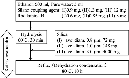
FIGURE 1. Schematic diagram of the florescent staining procedure.
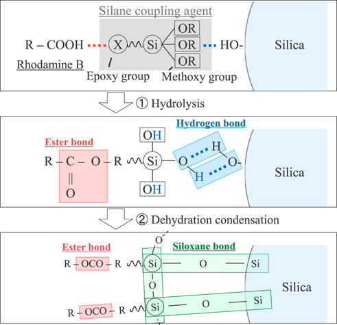
FIGURE 2. Schematic of silane coupling agent acts between the silica and Rhodamine.
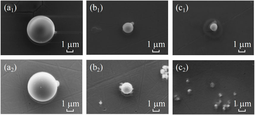
FIGURE 3. The SEM images of before and after staining process; 3.0 μm of before staining (a1) and after staining (a2), 1.0 μm of before (b1), and after (b2), and 0.8 μm of before (c1) and after (c2).
2.2 Observation equipment for in situ friction analysis
Friction tests were carried out using an in-situ observation system called “iFLAT” (Intelligent Fluorescent Light Assisted Tribometer) (Chiba et al., 2018; Takeno et al., 2020). A schematic of this system is depicted in Figure 4A, with an enlarged view of the observation area shown in Figure 4B. The iFLAT system is equipped with a 532 nm laser source (GLK32200, LASOS, Germany). This laser travels through a light guide from the source, enters an objective lens of an optical microscope, and is directed to the friction area via a sapphire disk (1.0 mm thickness, 50 mm diameter, with a surface roughness of approximately 2.0 nmRa). A fixed SUJ2 bearing ball (approximately 8.0 mm in diameter, with a surface roughness of approximately 7.0 nmRa, it is same property of AISI53200 stainless steel) within a ball holder is placed on a friction cantilever. A dead weight is used to apply a normal load of 0.2 N. The bearing ball reflects the incident laser, and the fluorescently stained particles emit fluorescent light. Both sets of light pass through the sapphire disk before reaching a half-mirror. Subsequently, both lights are directed to a WIG filter, which is a long-pass filter with a cutoff wavelength at 580 nm, effectively eliminating reflected laser light. Finally, the fluorescent light is captured by a CMOS camera, operating at a frame rate of 500 frames per second (fps). The in-situ observations were conducted multiple times, and we selected 60 frames (0.12 s) that recorded the highest particle counts within the observation area during the observations.
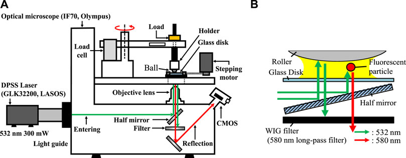
FIGURE 4. (A) Schematic of iFlat equipment, (B) schematic of inlet laser path through the glass disk to the contact point, and the reflection path through WIG filter.
2.3 Preparation and in situ friction test observation procedure
The friction test involved the interaction between an SUJ2 ball and a sapphire disk lubricated with PAO8 lubricant, which possesses a viscosity of 46.0 mm2/s at 40 °C. The i-FLAT system was utilized for this test. To prepare for the test, a 2.0–10 μL quantity of lubricant was applied onto the sapphire surface. Another sapphire disk was then placed over the lubricant to achieve a nearly uniform lubricant film. Subsequently, the upper sapphire disk was laterally removed, as illustrated in Figure 5 as a schematic representation. To ascertain the representative lubricant film thickness, ellipsometry was employed to measure the oil film thickness at a distance away from the contact area. The sapphire disk with the lubricant was secured onto the disk holder, with the ball specimen attached to it. A dead weight of 0.2 N was added to the ball specimen. Fluorescently stained particles, comprising a colloidal liquid of ethanol with a volume of 0.1 μL, were applied onto the oil film, positioned at the same radius as the friction test rotation, just ahead of the contact point as depicted in Figure 6. Prior to commencing the in-situ friction test, several minutes were allowed to pass to account for ethanol vaporization. The sliding speed was set at 5.0 mm/s (with a rotation radius of approximately 5.0 mm), and the camera operated at a speed of 500 frames per second (fps). We captured a continuous sequence of 60 frames (0.12 s) to tally the number of particles when the highest concentration of particles was observed near the contact point. The sliding distance covered in these 60 frames was approximately 0.6 mm.
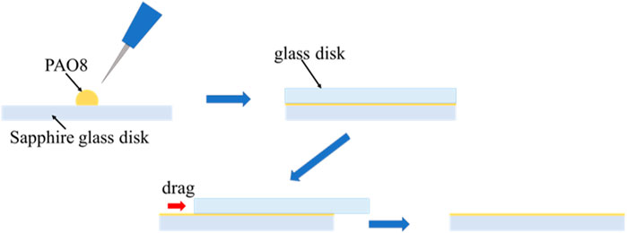
FIGURE 5. Schematic of oil film application on the glass disk before friction test.
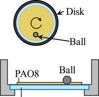
FIGURE 6. Schematic of contact area as top view and side view.
3 Results
3.1 The impact of the oil film thickness Hi on in situ observations
The in-situ observation results for particles with an average diameter (φ) of 3.0 μm and varying oil film thickness (Hi) are presented in Figure 7. The black dotted circle represents the Hertzian contact area, approximately 30 μm in size, under a normal load of 0.2 N. All friction tests were conducted under boundary lubrication conditions, resulting in the gap between the ball specimen and the sapphire disk at the contact point being at the utmost surface roughness level. The representative observation results for 3.0 μm diameter particles under a thin outside oil film thickness (Hi = 2.3 μm) are shown in Figures 7a1–a3. The circle marks one particle at 0 m, which then moved linearly along the sliding direction. This trend of linear particle motion remained consistent when the particle diameter was smaller than the outside oil film thickness. However, when the outside oil film thickness exceeded the particle diameter, as shown in Figures 7b1–b3 with Hi at 26.5 μm and Figures 7c1–c3 with Hi at 5,000 μm, the particle’s motion was no longer linear. In the case of the thick outside oil film situation with Hi = 5,000 μm, the particle indicated by the circle did not move along with the sliding direction.
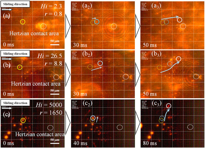
FIGURE 7. The in-situ observation results of 3.0 μm diameter particles; (A) Hi = 2.3 μm, r = 0.8; (B) Hi = 26.5 μm, r = 8.8; and (C) Hi = 5000 μm, r = 1650.
Figure 8 presents the results for φ = 1.0 μm diameter particles. In Figures 8a1–a3, where the outside oil film thickness was Hi = 2.5 μm, one particle indicated by a circle moved linearly along the sliding direction from Figures 8a1, a2, before stopping at the inlet area of contact as shown in Figure 8a3. However, for outside oil film thicknesses Hi = 12.7 μm (Figure 8b1–b3) and Hi = 1,650 μm (Figure 8c1–c3), the particles did not exhibit linear motion along the sliding direction. Finally, the results for 0.8 μm diameter particles are shown in Figures 9a1, c3. In cases where the outside oil film thickness was less than the average diameter of the particles, such as in Figures 9a1–a3 with Hi ≤ 0.75 μm, several particles halted just in front of the contact area.
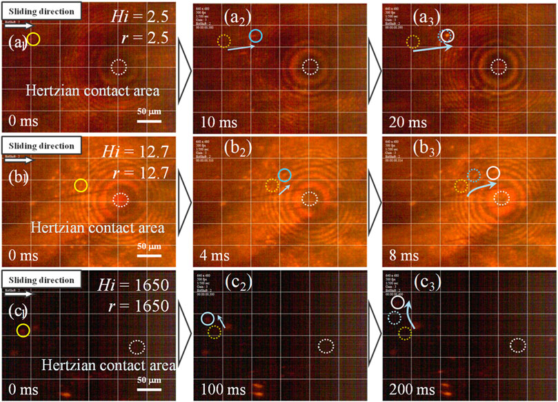
FIGURE 8. The in-situ observation results of 1.0 μm diameter particles; (A) Hi = 2.5 μm, r = 2.5; (B) Hi = 12.7 μm, r = 12.7; and (C) Hi = 1,650 μm, r = 1,650.
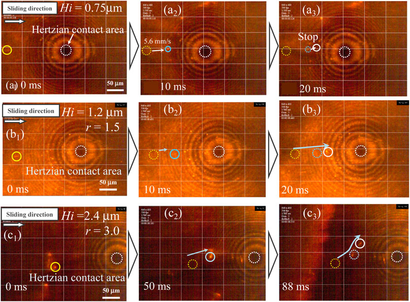
FIGURE 9. The in-situ observation results of 0.8 μm diameter particles; (A) Hi = 0.75 μm, r = 0.8; (B) Hi = 1.2 μm, r = 1.5; and (C) Hi = 2.4 μm, r = 3.0.
The measured number of entrainment particles, as a function of outside oil film thickness, is summarized in Figure 10. In every situation, the number of entrainment particles decreased with increasing outside oil film thickness, followed by a sharp increase to reach a peak. Subsequently, the number decreased again with greater outside oil film thickness. The peaks were observed at 4.0 μm outside oil film thickness for 3.0 μm diameter silica particles, 1.6 μm thickness for 1.0 μm diameter particles, and 1.4 μm thickness for 0.8 μm diameter particles, respectively.
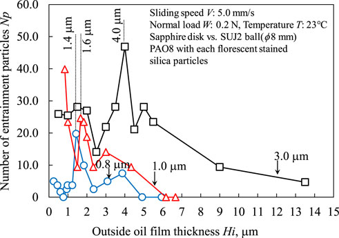
FIGURE 10. The relation between number of entrainment particles and outside oil film thickness.
3.2 The results of observations under dry conditions
To compare with a lubricated situation, we conducted in-situ dry friction tests using silica particles of varying diameters. The representative observation results are shown in Figure 11. In all situation, fluorescently stained particles accumulated in front of the contact area, and these accumulated particles did not move perpendicular to the sliding direction. Instead, they entered the contact point in large numbers.
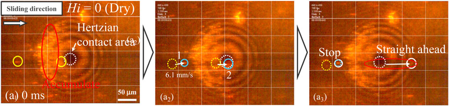
FIGURE 11. The in-situ observation under dry conditions.
4 Discussion
The relationship between the number of entrained particles and the non-dimensional value “r,” which represents the outside oil film thickness divided by the particle diameter, is summarized in Figure 12. In dry conditions, a substantial number of particles could enter the contact point regardless of their diameter. However, the entrainment number decreased when the “r” value approached approximately 1. Consequently, the maximum number of entrained particles increased within the range of 1 ≤ r ≤ 2. Beyond this range, the number of entrained particles gradually decreased. The reason behind this change in the number of entrained particles due to the “r” value is believed to be related to reverse flow in front of the contact point. A cross-sectional schematic image illustrating this phenomenon is presented in Figure 13. When “r” is less than or equal to 1 as shown in Figure 13i, the reverse flow creates a vortex with a radius smaller than that of the particles because the oil film thickness is less than the particle diameter. As a result, the vortex flow does not significantly affect the motion of particles. In the case where “r” falls within the range of 1 ≤ r ≤ 2 (Figure 13ii), a vortex flow is generated along the direction from the disk to the oil surface, with a vortex radius equal to the particle radius. Consequently, particles can move from the disk surface to the oil surface and back to the disk surface again. This enhances the maximum number of entrained particles. Finally, for values of “r” greater than or equal to 2 (Figure 13iii), the vortex flow radius becomes larger than the particle radius. Thus, once particles attach to the disk surface and follow the vortex flow, they are unable to return to the contact point. Based on the mechanisms described above, specific outside oil film thickness values that enhance the number of entrained particles is suggested.
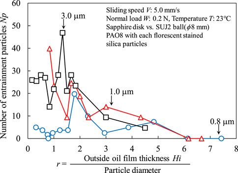
FIGURE 12. The relation between no-dimensional value r and number of entrainment particles.
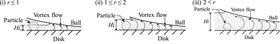
FIGURE 13. The relation between no-dimensional value r and number of entrainment particles. (i-iii) Schematic of a particle and vortex flow with different outside oil film thickness.
5 Conclusion
• We conducted investigations into the entrainment of glass beads with different diameters, such as 3.0 μm, 1.0 μm, and 0.8 μm. Utilizing a fluorescent staining technique facilitated by silane coupling, we were able to observe the contact point in-situ. The high-speed camera effectively detected the number of entrained particles.
• It was observed that particles could enter the contact point even under boundary lubrication conditions.
• The entrainment of particles depended on the thickness of the outside oil film. The non-dimensional value “r,” expressed as the outside oil film thickness (Hi) divided by the particle diameter, exhibited a clear relationship with the entrainment of particles. When “r” was less than or equal to 1, particles were capable of entering the contact point. In the range of 1 ≤ r ≤ 2, the maximum number of particles entered, while for “r” values greater than 2, the number of entrained particles gradually decreased.
Data availability statement
The raw data supporting the conclusion of this article will be made available by the authors, without undue reservation.
Author contributions
TT: Conceptualization, Data curation, Formal Analysis, Funding acquisition, Investigation, Methodology, Project administration, Resources, Software, Supervision, Validation, Visualization, Writing–original draft, Writing–review and editing. MO: Writing–original draft, Writing–review and editing. NF: Writing–original draft, Writing–review and editing. MM: Writing–original draft, Writing–review and editing. NH: Writing–original draft, Writing–review and editing. RT: Writing–original draft, Writing–review and editing. HS: Writing–original draft, Writing–review and editing. NU: Writing–original draft, Writing–review and editing.
Funding
The author(s) declare financial support was received for the research, authorship, and/or publication of this article. This paper is based on results obtained from a project, JPNP20004, subsidized by New Energy and Industiral Technology Development Organization (NEDO).
Conflict of interest
The authors declare that the research was conducted in the absence of any commercial or financial relationships that could be construed as a potential conflict of interest.
Publisher’s note
All claims expressed in this article are solely those of the authors and do not necessarily represent those of their affiliated organizations, or those of the publisher, the editors and the reviewers. Any product that may be evaluated in this article, or claim that may be made by its manufacturer, is not guaranteed or endorsed by the publisher.
References
Abdollah, M. F. B., Yamaguchi, Y., Akao, T., Inayoshi, N., Miyamoto, N., Tokoroyama, T., et al. (2012a). Deformation-wear transition map of DLC coating under cyclic impact loading. Wear 274–275 (27), 435–441. doi:10.1016/j.wear.2011.11.007
Abdollah, M. F. B., Yamaguchi, Y., Akao, T., Inayoshi, N., Umehara, N., and Tokoroyama, T. (2010). Phase transformation studies on the a-C coating under repetitive impacts. Surf. Coat. Technol. 205 (2), 625–631. doi:10.1016/j.surfcoat.2010.07.062
Abdollah, M. F. B., Yamaguchi, Y., Akao, T., Inayoshi, N., Umehara, N., and Tokoroyama, T. (2011). The effect of maximum normal impact load, absorbed energy, and contact impulse, on the impact crater volume/depth of DLC coating. Tribol. Online 6 (6), 257–264. doi:10.2474/trol.6.257
Abdollah, M. F. B., Yamaguchi, Y., Akao, T., Miyamoto, N., Tokoroyama, T., Umehara, N., et al. (2012b). Future developments of a deformation-wear transition map of DLC coating. Tribol. Online 7 (3), 107–111. doi:10.2474/trol.7.107
Bukvić, M., Gajević, S., Skulić, A., Savić, S., Ašonja, A., and Stojanović, B. (2023). Tribological application of nanocomposite additives in industrial oils. Lubricants 12, 6. doi:10.3390/lubricants12010006
Chiba, S., Igami, T., and Tokoroyama, T. (2018). The in-situ observation of contact point under boundary lubrication condition with imitation wear particles. J. Mat. Test. Res. Assoc. Jpn. 63 (1), 17–21.
Cusano, C., and Sliney, H. E. (1982a). Dynamics of solid dispersions in oil during the lubrication of point contacts, Part I—graphite. ASLE Trans. 25 (2), 183–189. doi:10.1080/05698198208983079
Cusano, C., and Sliney, H. E. (1982b). Dynamics of solid dispersions in oil during the lubrication of point contacts, Part II—molybdenum disulfide. ASLE Trans. 25 (2), 190–197. doi:10.1080/05698198208983080
Dwyer-Joyce, R. (1999). Predicting the abrasive wear of ball bearings by lubricant debris. Wear 233–235, 692–701. doi:10.1016/S0043-1648(99)00184-2
Gao, R., Liu, W., Chang, Q., Zhang, H., and Liu, Y. (2021). Tribological property of biocarbon-based magnesium silicate hydroxide nanocomposite as lubricant additive at different concentrations of additive and dispersant. Trans. ASME J. Tribol. 143 (7), 071901. doi:10.1115/1.4048725
Hong, W., Cai, W., Wang, S., and Tomovic, M. M. (2018). Mechanical wear debris feature, detection, and diagnosis: a review. Chin. J. Aero 31 (5), 867–882. doi:10.1016/j.cja.2017.11.016
Iwai, Y., Honda, T., Miyajima, T., Yoshinaga, S., Higashi, M., and Fuwa, Y. (2010). Quantitative estimation of wear amounts by real time measurement of wear debris in lubricating oil. Tribol. Int. 43 (1–2), 388–394. doi:10.1016/j.triboint.2009.06.019
Kassim, K. A. M., Tokoroyama, T., Murashima, M., Lee, W.-Y., Umehara, N., and Mustafa, M. M. B. (2021). Wear acceleration of a-C:H coatings by Molybdenum-derived particles: mixing and temperature effects. Tribol. Int. 159, 106944. doi:10.1016/j.triboint.2021.106944
Kassim, K. A. M., Tokoroyama, T., Murashima, M., and Umehara, N. (2020). The wear classification of MoDTC-derived particles on silicon and hydrogenated diamond-like carbon at room temperature. Tribol. Int. 147, 106176. doi:10.1016/j.triboint.2020.106176
Kinoshita, H., Kaneda, S., Fujii, T., and Mari, O. (2007). Three-dimensional measurement and visualization of internal flow of a moving droplet using confocal micro-PIV. Lab. Chip 7, 338–346. doi:10.1039/B617391H
Lee, J., Jo, S. H., and Lim, J. (2019b). Effect of surface modification of CaCO3 nanoparticles by a silane coupling agent methyltrimethoxysilane on the stability of foam and emulsion. J. Industrial Eng. Chem. 74, 63–70. doi:10.1016/j.jiec.2019.02.002
Lee, W. Y., Jang, Y. J., Umehara, N., Tokoroyama, T., and Murashima, M. (2020). Effect of defects on wear behavior in ta-C coating prepared by filtered cathodic vacuum arc deposition. Diam. Relat. Mater 105, 107789. doi:10.1016/j.diamond.2020.107789
Lee, W. Y., Tokoroyama, T., Jang, Y. J., and Umehara, N. (2018). Effect of substrate bias and temperature on friction and wear properties for ta-C coating prepared under different substrate bias voltages with filtered cathodic vacuum arc deposition. Tribol. Online 13 (5), 241–247. doi:10.2474/trol.13.241
Lee, W. Y., Tokoroyama, T., Jang, Y. J., and Umehara, N. (2019a). Investigating running-in behavior to understand wear behavior of ta-C coating with filtered cathodic vacuum arc deposition. J. Tribol. 23, 38–47.
Loewenthal, S. H., and Moyer, D. W. (1979). Filtration effects on ball bearing life and condition in a contaminated lubricant. ASME, J. Tribol. 101 (2), 171–176. doi:10.1115/1.3453307
Mishina, H., Kohno, A., and Akamatsu, A. (2003). Discovery of elemental debris of adhesive wear particles and primary process of wear. Tribologists 48 (4), 307–314.
Mitchell, D. J., Mecholsky, J. J., and Adair, J. H. (2000). All-steel and Si3N4-steel hybrid rolling contact fatigue under contaminated conditions. Wear 239, 176–188. doi:10.1016/s0043-1648(99)00369-5
Nomede-Martyr, N., Bilas, P., Thomas, P., Minatchy, G., and Romana, L. (2021). Tribological performances of graphite and hexagonal boron nitride particles in the presence of liquid. Trans. ASME J. Tribol. 143, 071401. doi:10.1115/1.4048550
Roylance, B. J., Williams, J. A., and Dywer-Joyce, R. (2000). Wear debris and associated wear phenomena–fundamental research and practice. IMechE J. Eng. Trib. 214, 79–105. doi:10.1243/1350650001543025
Shi, S., Wang, X., Li, Z., Meng, J., Chu, X., Zhang, P., et al. (2023). Multifunctional integrated superhydrophobic coatings with unique fluorescence and micro/micro/nano-hierarchical structures enabled by in situ self-assembly. ACS Appl. Mater. Interfaces 15 (5), 7442–7453. doi:10.1021/acsami.2c21531
Shin, Y., Lee, D., Lee, K., Ahn, K. H., and Kim, B. (2008). Surface properties of silica nanoparticles modified with polymers for polymer nanocomposite applications. J. Indust Eng. Chem. 14, 515–519. doi:10.1016/j.jiec.2008.02.002
Strubel, V., Fillot, N., Cavoret, J., Vegne, P., Mondelin, A., Maheo, Y., et al. (2016). Particle entrapment in hybrid lubricated point contacts. Tribol. Trans. 59 (4), 768–779. doi:10.1080/10402004.2015.1106631
Strubel, V., Fillot, N., Ville, F., Cavoret, J., Vergne, P., Mondelin, A., et al. (2017a). Particle entrapment in rolling element bearings: the effect of ellipticity, nature of materials, and sliding. Tribol. Trans. 60 (2), 373–382. doi:10.1080/10402004.2016.1168901
Strubel, V., Simoens, S., Vergne, P., Fillot, N., Ville, F., Hajem, M. E., et al. (2017b). Fluorescence tracking and µ-PIV of individual particles and lubricant flow in and around lubricated point contacts. Tribol. Lett. 65, 75. doi:10.1007/s11249–017–0859–z
Takeno, H., Tokoroyama, T., Murashima, M., Umehara, N., and Chiba, S. (2020). Enhancement of speed of surface roughness improvement by using a two mixed abrasive slurry method to polish glass surfaces. J. Jpn. Soc. Abras. Technol. 64 (8), 428–435. doi:10.11420/jsat.64.32
Tallian, T. E. (1976). Prediction of rolling contact fatigue life in contaminated lubricant: Part I—mathematical Model. ASME, J. Tribol. 98 (2), 251–257. doi:10.1115/1.3452814
Tokoroyama, T., Kamiya, T., Ahmed, NSBH, and Umehara, N. (2018). Collecting micrometer-sized wear particles generated between DLC/DLC surfaces under boundary lubricatin with electric field. JSME Mech. Eng. Lett. 4, 18–00089. doi:10.1299/mel.18-00089
UN (2015). Transforming our world: the 2030 agenda for sustainable development. Available at: https://sdgs.un.org/2030agenda.
Wang, L., Snidle, R. W., and Gu, L. (2000). Rolling contact silicon nitride bearing technology: a review of recent research. Wear 246, 159–173. doi:10.1016/S0043–1648(00)00504–4
Wang, W., Wong, P. L., He, F., and Wan, G. T. Y. (2007). Experimental study of the smoothing effect of a ceramic rolling element on a bearing raceway in contaminated lubrication. Tribol. Lett. 28, 89–97. doi:10.1007/s11249–007–9251–8
Wu, C., Yang, K., Chen, Y., Ni, J., Yao, L., and Li, X. (2021). Investigation of friction and vibration performance of lithium complex grease containing nano-particles on rolling bearing. Tribol. Int. 155, 106761. doi:10.1016/j.triboint.2020.106761
Keywords: in-situ, fluorescent staining, Rhodamine B, silane coupling, oil film thickness
Citation: Tokoroyama T, Okashita M, Fusetani N, Murashima M, Hashizume N, Tsuboi R, Shiomi H and Umehara N (2024) The 1 μm wear particles entrainment in situ observation via fluorescent staining silica particles by silane coupling with Rhodamine B. Front. Mech. Eng 10:1371948. doi: 10.3389/fmech.2024.1371948
Received: 17 January 2024; Accepted: 13 February 2024;
Published: 28 February 2024.
Edited by:
Sorin-Cristian Vladescu, King’s College London, United KingdomReviewed by:
Milan Bukvic, University of Kragujevac, SerbiaMladen Radojković, University of Priština in Kosovska Mitrovica, Serbia
Copyright © 2024 Tokoroyama, Okashita, Fusetani, Murashima, Hashizume, Tsuboi, Shiomi and Umehara. This is an open-access article distributed under the terms of the Creative Commons Attribution License (CC BY). The use, distribution or reproduction in other forums is permitted, provided the original author(s) and the copyright owner(s) are credited and that the original publication in this journal is cited, in accordance with accepted academic practice. No use, distribution or reproduction is permitted which does not comply with these terms.
*Correspondence: T. Tokoroyama, dGFrYXl1a2kudG9rb3JveWFtYUBtYWUubmFnb3lhLXUuYWMuanA=