 Hongqiang Guan
94% of researchers rate our articles as excellent or good
Learn more about the work of our research integrity team to safeguard the quality of each article we publish.
Find out more
ORIGINAL RESEARCH article
Front. Mech. Eng., 10 May 2024
Sec. Mechatronics
Volume 10 - 2024 | https://doi.org/10.3389/fmech.2024.1371218
This article is part of the Research TopicIntegrative Engineering for Smart SystemsView all articles
Introduction: The dynamic positioning system resists the environmental forces such as wind, wave and current acting on the ship through the thruster, so that the ship can remain in the position required by the sea level as much as possible, and the operation is very convenient. But its current dynamic positioning ability can not meet people's needs.
Methods: A Kalman filter based on untracked optimization was designed for dynamic positioning control system. Then the intelligent control algorithm is designed for the dynamic positioning top-level controller and thrust optimal distribution controller, which occupy an important position in the system, namely the adaptive weight variation particle swarm optimization algorithm and thrust optimal distribution algorithm.
Results and Discussion: The average position error of three degrees of freedom after filter processing is 1.53 m. Compared with other mainstream controllers, the mean root error of controllers based on adaptive weight variation particle swarm optimization in environment A and B is 2.295 and 1.8 m, respectively. In environment C, the controller based on thrust optimization allocation algorithm can get the optimal solution when the full rotary thruster reaches the 7 s and the channel thruster reaches the 4 s. The thrust exclusion zone is crossed at 46 s in environment D. In the dynamic positioning capability curve of the system, the experimental hull can balance the different environmental loads at all angles. In summary, the intelligent control algorithm proposed in this paper can effectively improve the positioning ability of the dynamic positioning control system and meet the needs of people for ship navigation today.
In the field of marine engineering, Dynamic Positioning Control (DPC) is a key technology to ensure the stable positioning of ships and other equipment. However, due to the complexity and uncertainty of the marine environment, traditional control methods are difficult to achieve efficient and stable positioning (Kandemir and Celik, 2021; Ltd, 2021; Wang et al., 2021). The continuous development of Intelligent Control Algorithms (ICA) has made their application and optimization in DPC systems a research focus (Choudhuri et al., 2023; Dornelas and Lima, 2023). Among them, Particle Swarm Optimization (PSO) is widely used in various fields due to its advantages of simple operation and fast convergence speed, but it has problems such as sensitivity to initial parameters (Tsai and Fredrickson, 2022; Amiri et al., 2023). In response to the above issues, this study first introduces an unscented transformation based on Kalman Filter (KF) to obtain an Unscented Kalman Filter (U-KF) state estimator. Then, adaptive weight mutation particle swarm optimization (AWM-PSO) and Thrust Optimization Allocation (TOA) algorithms are designed for the Power Positioning Top Layer (PPTL) and TOA controllers. This study aims to improve the performance and stability of DPC systems, enabling ships to better cope with complex and changing marine environments. There are three main innovative points in the research. The first point is the proposed U-KF filter for DPC localization State Estimation (SE). The second point is to design the AWM-PSO algorithm and TOA algorithm for the PPCL and TOA controllers of the DPC system, respectively. The third point is the innovation of the theoretical model, which constructs a mathematical model of the ship’s DPC system based on the characteristics of the research vessel, and simplifies it. This facilitates subsequent research and demonstrates the characteristics of the ship’s hull. The research structure is mainly divided into four parts. Part 1 is a review of relevant research findings. Part 2 is the design of mathematical models for ship-based DPC systems, U-KF-based Dynamic Positioning State Estimation (DPSE) methods, and AWM-PSO and TOA algorithms. Part 3 is a validation of the performance of the research method. Part 4 is a summary of the research. This study aims to achieve safe and normal operation of ships in complex sea conditions, providing accurate environmental interference information for subsequent control design. A controller designed with strong anti-interference ability under allowable working conditions can switch control strategies in a timely manner when exceeding the threshold range, quickly evacuate dangerous areas, and avoid risks.
In recent years, China has shifted its focus to becoming a maritime power. The DPC system can achieve positioning solely through configured power devices while avoiding environmental disturbances. It has high maneuverability and positioning accuracy, which can well meet the needs of navigation work. However, in the face of complex marine environments, the system also struggles to maintain long-term positioning, posing a threat to personnel and property on board ships. However, traditional control methods are difficult to achieve ideal results in complex environments such as non-linearity and uncertainty. Therefore, scholars are exploring the application of ICA in control systems. Numerous scholars have conducted in-depth discussions on this topic. Qian et al. proposed two methods, angle droop control based on global positioning system and V-I, to achieve synchronization of distributed power generation units. They also designed an impedance and internal controller method that balances stability constraints and power quality. This control method could effectively improve the dynamic response and stability of the system (Qian et al., 2021). In specific environmental protection areas, large yachts cannot be anchored using traditional mooring systems and require the use of DPC systems. Therefore, Mauro et al. designed a dynamic positioning analysis method that combines DPC system with comfort assessment and scatter plot to achieve accurate positioning, which enhances the comfort level (Mauro et al., 2021). However, the DPC system mentioned above did not consider all possible wave combinations in the sea area. It could only calculate the downtime of each DPC system in the specific sea area where the yacht operates. The proposed ICA can effectively handle environmental interference information in different sea areas, providing accurate environmental interference information for navigation. Zhang et al. proposed a single input optimized composite adaptive neural control algorithm for the practical limitation problem of ships, and ensured the final bounded stability of all error signals in the DPC closed-loop system through Lyapunov theory. The simulation results have verified the effectiveness of the algorithm (Zhang et al., 2021a). Shi and Hu designed a real-time control algorithm for the special application environment of underground tunnels and applied it to the actual automatic driving control of parallel bar diesel scrapers. This control algorithm could achieve a balance between stability and real-time performance (Shi and Hu, 2022). Zhang et al. artificially extended the application of personnel movement positioning in tunnel safety construction and designed a wavelet threshold denoising method for personnel movement positioning. The positioning algorithm used a three sided positioning algorithm based on symmetrical double-sided bidirectional ranging. This method had good motion positioning effect and high positioning accuracy (Zhang et al., 2021b). Lin et al. designed a flexible energy scheduling algorithm to solve the problem of high inter continuity in pulse loads of integrated power system ships in a short period of time. The test results have verified the effectiveness of the algorithm (Lin et al., 2021). The application of the above ICAs in power system ships can effectively reduce energy consumption, while the proposed ICA can simultaneously balance economy, accuracy, and safety. Bai et al. proposed an improved adaptive U-KF algorithm for personnel localization in complex and location-based coal mining environments. The performance of this algorithm has been proven to be superior (Bai et al., 2022). Da et al. designed a composite algorithm of fuzzy proportional integral derivative (PID) controller and acceleration closed-loop control to address the drawbacks of slow response and large oscillation in laser cutting tracking systems. This algorithm could achieve efficient servo control while ensuring positioning accuracy (Da et al., 2022).
Based on the above content, it can be concluded that while many research results currently offer advantages such as good performance and economy, they lack maneuverability and are vulnerable to external environments. Additionally, as water depth increases, the manufacturing and safety costs of DPC systems will also increase significantly. ICAs are characterized by their learning ability, which allows them to learn from past experiences and their environment. They can summarize general conclusions from specific cases and learn from the learning controller of the control system by issuing control instructions to the object and utilizing feedback information. This ability improves the performance of the closed-loop system. To better cope with external environmental interference, reduce energy consumption and ensure the safety of ships under adverse sea conditions, PPTL and TOA controllers for DPC systems are studied, and the two ICAs, AWM-PSO and TOA algorithms, are designed.
The DPC system is very suitable for offshore operations. But with the increasing demand for ship operations, higher requirements have been put forward for the stability of ships in complex sea conditions. In response to the above issues, this study first constructs a mathematical model of a ship-based DPC system for experimentation, and then designs a DPSE method based on U-KF. Finally, corresponding AWM-PSO and TOA algorithms are proposed for the most critical PPTL and TOA in the DPC system.
During navigation or positioning tasks, ships may be affected by random factors from complex environments, causing them to deviate from their course. At this point, it is necessary to use the propulsion power device to generate a reverse force, so that the ship can navigate according to the expected route (Zhao et al., 2022; Zhou et al., 2022). Therefore, it is necessary to first build a mathematical model of the DPC system to facilitate the subsequent process. Before analyzing the force situation of the ship, it is necessary to make assumptions that the experimental ship is a rigid body, in still water, and has a fixed draft during navigation. Then, the expressions for the translational and rotational motion of the experimental vessel can be obtained through the momentum theorem and the moment of momentum theorem, as shown in Eq. 1.
In Equation 1,
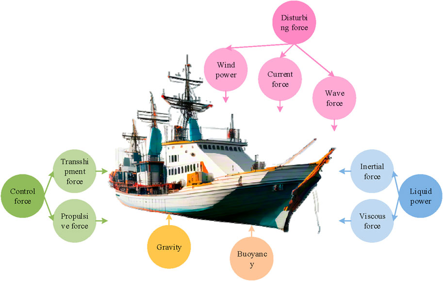
Figure 1. Schematic diagram of force analysis for experimental ship hull.
In Figure 1, the experimental ship’s forces are mainly divided into three categories: interference force, control force, and fluid dynamics. The expression of the ship’s force situation is Eq. 2.
In Eq. 2,
Then, separated modeling is used to classify and model the ships, while the hydrodynamic function is dimensionless with a reference area of
In Eq. 4,
In Eq. 5,
Due to the influence of the environment on the movement of ships in complex oceans, the corresponding motion state exhibits a mixed motion state of low frequency and high frequency. The sensor also collects a mixture of multiple signals, including low-frequency components, high-frequency components, random disturbance signals, and measurement noise. This study employs a SE filter to eliminate extraneous high-frequency components and measurement noise from mixed signals, and outputs only the low-frequency signals necessary for the DPC system. The working principle of the SE filter for the DPC system is Figure 2.
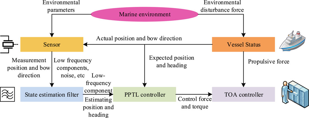
Figure 2. The working principle of SE filters for DPC systems.
This study divides the motion state of the ship into low frequency and high frequency, and constructs corresponding mathematical models. The expression is Eq. 6.
In Eq. 6,
In Eq. 7,
In Eq. 8,
The schematic diagram of the NP filter structure can be obtained through the above process, as shown in Figure 3.
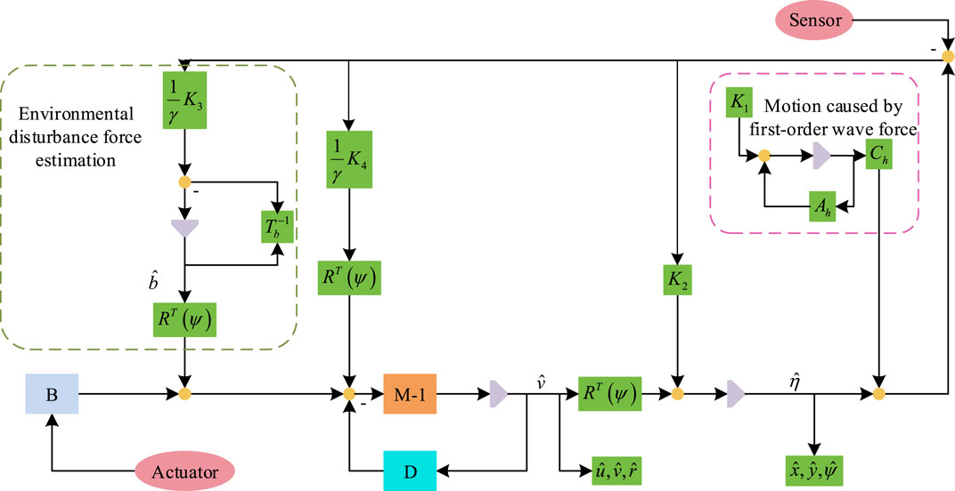
Figure 3. Structural diagram of NP filter.
In NP filters, the error system can be divided into two linear subsystems, as expressed in Eq. 10.
In Eq. 10,
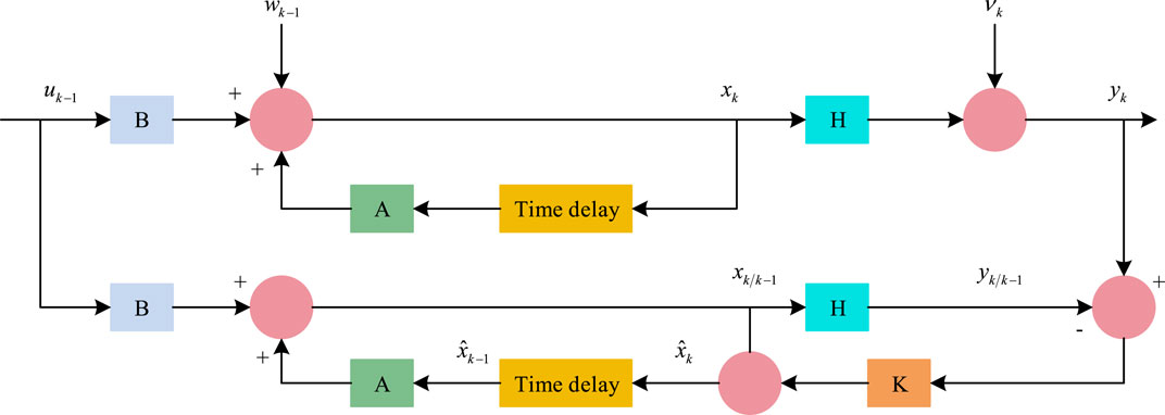
Figure 4. Principle of KF.
In Figure 4, U-KF only replaces the linearization of the nonlinear part with an unscented transformation, processes the mean and covariance through nonlinear transfer, and approximates the posterior probability density of the original system state using specific samples. By measuring the actual motion state data collected by the measurement system, the optimal estimation of the position and other state variables of the experimental ship at different times can be obtained based on the principle of U-KF. Firstly, a set of Sigma point sets with corresponding weights are obtained according to the traceless transformation, as shown in Eq. 11.
In Eq. 11,
The ship’s position, heading, and speed motion state variables' one-step prediction and covariance matrices are computed by a weighted summation of the predicted values of the sampled points of the ship’s motion state. The corresponding weights are obtained by UT transformation, and the computation is shown in Eq. 13.
In Eq. 13,
The weighted sum operation is performed on Eq. 14 to obtain the corresponding mean and covariance. Then the KF gain of the ship motion state denoising filter is calculated to obtain the updated ship motion state and covariance, which is calculated in Eq. 15.
In Eq. 15,
To enhance the effectiveness of the DPC system’s control, this study optimizes the control algorithms for the most critical PPTL and TOA in the system. Among them, PPTL analyzes the filtered signal processed by the state estimator mentioned above, and takes the expected position and required force and torque in the bow direction as inputs to TOA, enabling the DPC system to complete closed-loop. In traditional PPTL, due to the interaction and adjustment of parameters, the control effect of DPC system is unstable, and in practical situations, it is usually expected to achieve the optimal control of multiple objectives as much as possible. Therefore, this study introduces intelligent optimization algorithms to achieve intelligent control of PPTL. PSO is widely used in various optimization problems due to its advantages of simple operation and fast convergence, but there are problems such as balancing local optimization and global optimization. In response to the above issues, this study combines mutated particles with dynamic weights, designs a dynamic adaptive weight strategy and mutated particle strategy, and obtains the AWM-PSO algorithm. In the dynamic adaptive weight section, the expression for evolution factor
In Eq. 16,
In Eq. 17,
In Eq. 18,
In Eq. 19,
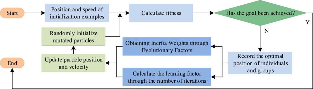
Figure 5. Schematic diagram of AWM-PSO algorithm.
In TOA, the first step is to build a thruster model. The calculation of thrust
In Eq. 20,
In Eq. 21,
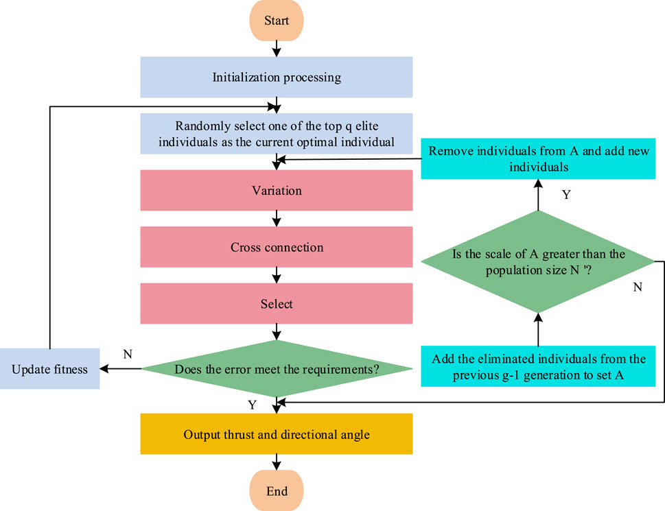
Figure 6. Schematic diagram of TOA algorithm flow.
In Figure 6, the TOA algorithm only needs to select individuals within the defined domain to obtain corresponding fitness values. After obtaining the global optimal solution, the thrust and azimuth of all thrusters can be obtained through the corresponding individuals, completing the thrust allocation work of the DPC system.
To explore the performance of two types of ICA for DPC systems, this study first conducted preliminary experiments to verify the performance of the DPC system, and then analyzed the effects of the two ICAs in different simulation environments.
To ensure the accuracy of subsequent controller simulations, it is necessary to first verify the effectiveness of the experimental vessel. Table 1 shows the relevant parameters of the experimental ship.
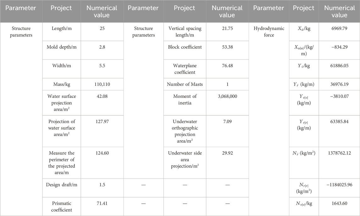
Table 1. Setting of relevant parameters for the experimental hull.
The proposed experimental vessel is equipped with two fully rotating thrusters and one channel thruster, denoted as Q1, Q2, and C3, respectively. When conducting open-loop model simulation, environmental loads are not introduced. The initial state of the experimental ship is stationary, with thrust and bow turning forces of 3*103 N and 4*104 N/m, respectively.
Figure 7 shows the open-loop simulation results of the experimental ship model. Figures 7A,B show the comparison of the navigation trajectory and velocity results of the experimental ship, respectively. After being subjected to constant thrust and turning moment, the experimental ship exhibits a continuous increasing trend in lateral velocity, longitudinal velocity, and turning speed, and finally maintains a stable state. In addition, the navigation trajectory of the experimental ship is arc-shaped, indicating that the constructed model can achieve steady rotational motion conditions and can be used as a research object for subsequent experiments. To further validate the experimental ship model proposed in the study, Z-shaped simulation experiments were conducted using a 25 m long real ship model equipped with two thrusters and one channel thruster, as well as a Nomoto model.
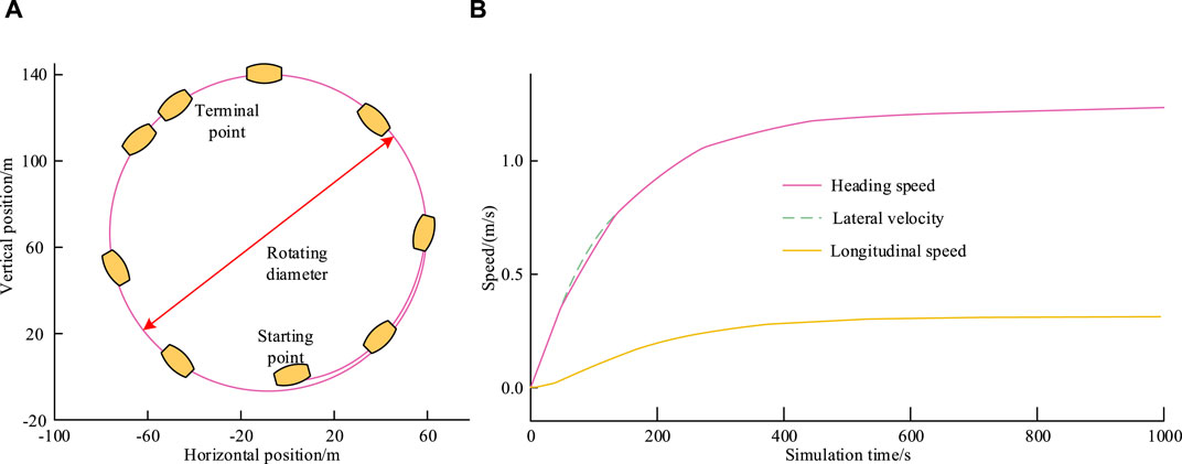
Figure 7. Open loop model simulation results for experimental ship models. (A) Navigation trajectory (B) Ship simulation speed results.
The accuracy results of different models based on Z-shaped experiments are shown in Figure 8. From Figure 8, the proposed experimental ship model has higher accuracy than the Nomoto model, and the simplicity of the model is confirmed. In summary, the proposed model is effective and highly accurate, and can be well used in subsequent experimental analysis. To test the filtering effect of the U-KF ship motion state estimator in the DPC system, this study selects a navigation process for simulation experiments. The initial position is at (20, 20), with lateral and longitudinal velocities of 0.6 m/s and 0.7 m/s, respectively. The initial heading is 50°, and a change of 0.5° per second is set, with a total duration of 100 s. Sampling is conducted every 1 s.
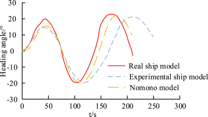
Figure 8. Accuracy results of different models based on Z-shaped experiments.
Figure 9A–D show the trajectory, lateral position error, longitudinal position error, and heading angle error of the experimental ship motion SE processed by different filters. Figure 9 shows that there is a significant difference between the actual navigation trajectory of the experimental vessel and the observed navigation trajectory, and the U-KF processed navigation trajectory has a better effect. In the lateral position error, the error processed by U-KF and NP filters is within the range of ±1.6 m and ±3.9 m. In the longitudinal position error, the error processed by the two filters is within the range of ±1.0 m and ±2.7 m. In the heading angle error, the errors processed by the two filters are within ±2° and ±3°. The above results indicate that the proposed U-KF-based ship DPSE method has good filtering and SE effects, providing accurate data for subsequent ICA.
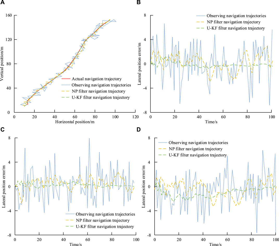
Figure 9. Simulation effect of experimental ship SE under different filters. (A) Trajectory estimation of experimental ship motion states processed by different filters. (B) Lateral position error of experimental ship motion state estimation processed by different filters (C) Longitudinal position error of experimental ship motion state estimation processed by different filters. (D) Heading position error of experimental ship motion state estimation processed by different filters.
This study first tests the effectiveness of the AWM-PSO algorithm for PPTL in DPC systems and evaluates it using Root Mean Square Error (RMSE). At the same time, this study set up two environments for experiments. Environment A is the case without environmental disturbance, where the initial and expected positions are [0 m, 0 m, 10°] and [100 m, 100 m, 20°], respectively. Environment B refers to the presence of environmental disturbances, with wind speed, flow velocity, wind direction angle, flow direction angle, and sea state set at 11 m/s, 0.5 m/s, 0°, 0°, and level three, respectively. In addition, the parameter settings for the AWM-PSO algorithm are as follows:
Figures 10A, B show the trajectory and three degree of freedom position RMSE results obtained by different controllers in environment A. The navigation trajectory error under the LQF controller is the largest, and the PPTL based on the AWM-PSO algorithm can reach the desired position through the shortest path and minimum error. In addition, compared with other controllers, the proposed controller has the smallest RMSE corresponding to the lateral, longitudinal, and bow directions, which are 1.294 m, 1.335 m, and 4.257 m, respectively. Additionally, both LQF and PID controllers exhibit a relatively fast response speed, but with noticeable overshoot. They both require approximately 160 s to reach the expected value. This may be due to changes in the input and output signals, or the characteristics of the controlled object (Chen et al., 2024). Figures 10C, D show the trajectory and three degree of freedom position RMSE results obtained by different algorithm controllers in environment B. The proposed controller has the best control effect in three degrees of freedom motion, with an average RMSE stable within 1.8 m. The above results indicate that PPTL based on AWM-PSO algorithm has good stability and dynamic performance. Secondly, to test the performance of TOA’s ICA, this study conducts experiments in two different environments. Environment C is a constant thrust command, where the installation coordinates, maximum thrust, and forbidden zone angle for Q1, Q2, and C3 are (−11.50, −1.05), 42,500 and (70,120), (−11.50, −1.05), 42,500 and (250,300), (7.28, 0), and 7,600, respectively. In addition,
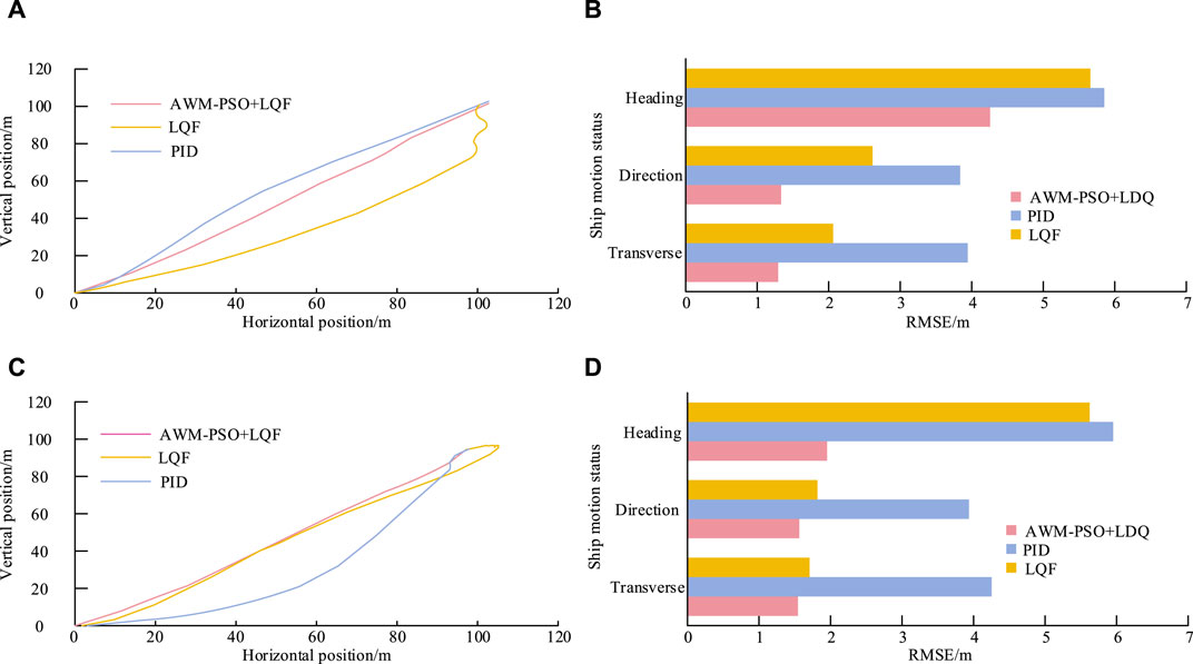
Figure 10. RMSE results of trajectories and three degrees of freedom positions controlled by different algorithm controllers in environment A and environment B. (A) Trajectories of different controllers in environment A. (B) Comparison of RMSE Results for Different Controllers in Environment A (C) Trajectories of different controllers in environment B (D) Comparison of RMSE Results for Different Controllers in Environment B.
Figure 11A–C show the thrust angle effects of controllers Q1, Q2, and C3 before and after optimization under environment C. Q1 can be disabled for 3 s to cross the set penalty area angle, at which point the thrust drops to 0. Q2 has completed crossing the thrust penalty area after startup. The optimal solution can be obtained when the fully rotating thruster reaches the 7th second and C3 reaches the 4th second, after which the thrust angle remains stable. The above results indicate that both fully rotating thrusters can cross the thrust forbidden zone during the adjustment process, verifying that the proposed algorithm can meet the constraints of the thruster. In addition, the thrust and directional angle generated by the full rotation thruster and the channel thruster will constantly change before the overall combined force reaches the set value. This may be because the research algorithm needs to reduce the error between the expected force and the thruster force and continuously adjust it, search for the optimal thrust and directional angle of the thruster in feasible solutions, and maintain stable output (Xie et al., 2023). Figure 11D–F show the thrust angle effects of controllers Q1, Q2, and C3 based on the TOA algorithm in environment D. Q2 achieved a thrust penalty zone crossing in the 46th second, at which point the thrust was 0. Finally, to verify the effectiveness of the DPC system in maintaining position in a certain navigation environment, this study uses the commonly used Dynamic Positioning Capability Curve (DPCC) for estimating evaluation criteria, and uses the IMCA environmental condition standard as the simulation environmental condition.
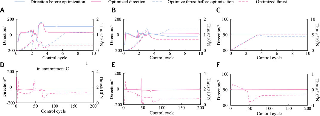
Figure 11. Performance results of propulsion systems under environment C and environment D. (A) Thrust angle variation curve of Q1 in environment C (B) Thrust angle variation curve of Q2 in environment C (C) Thrust angle variation curve of C3 in environment C (D) Thrust angle variation curve of Q1 in environment D (E) Thrust angle variation curve of Q2 in environment D (F) Thrust angle variation curve of C3 in environment D.
Figure 12 shows the simulation effect of DPCC based on DPC system. The experimental ship can balance environmental loads with significant differences at different angles, but its positioning ability is relatively weak in the directions of 40°–80° and 280°–340°. In summary, research algorithm can effectively improve the dynamic positioning and control capabilities of DPC systems, and has good applicability.
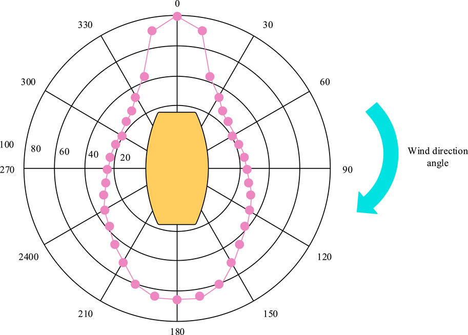
Figure 12. Simulation effect of DPCC based on DPC system.
The rapid development of society has made it difficult for land resources to meet people’s energy needs, so countries around the world are turning to the development of abundant marine resources. However, ships are highly susceptible to external environmental disturbances, making it difficult to maintain their positioning and resulting in ship collision accidents. To overcome the impact of environmental disturbances, this study first designed an experimental ship model, then constructed a U-KF for DPSE, and finally designed two types of ICAs: AWM-PSO and TOA. The experiment showed that in the three degree of freedom position error, the average errors after NP filter and U-KF processing were ±3.2 m and 1.53 m, respectively. Compared with PID and LQF controllers, the controller based on AWM-PSO algorithm in environment A had the smallest RMSE corresponding to the lateral, longitudinal, and bow directions, which were 1.294 m, 1.335 m, and 4.257 m, respectively. The average RMSE of the controller in environment B was stable within 1.8 m. The optimal solution could be obtained in environment C when Q1 and Q2 reached the 7th second, and C3 reached the 4th second. In environment D, the thrust penalty area was crossed in the 46th second. In the DPCC effect of the DPC system, the experimental ship could achieve balanced environmental loads with significant differences at all angles. In summary, the two proposed ICAs can effectively improve the dynamic positioning and control performance of DPC systems, and still have good application effects in complex navigation environments. However, there are still shortcomings in the research. This study focuses on the independent design of the two controllers in the DPC system, and the connection between the two can be further improved. In future research, more advanced methods can be used to enhance the coupling ability between various parts of the DPC system.
The original contributions presented in the study are included in the article/supplementary material, further inquiries can be directed to the corresponding author.
HG: Conceptualization, Data curation, Formal Analysis, Methodology, Supervision, Validation, Writing–original draft, Writing–review and editing.
The author(s) declare that no financial support was received for the research, authorship, and/or publication of this article.
The author declares that the research was conducted in the absence of any commercial or financial relationships that could be construed as a potential conflict of interest.
All claims expressed in this article are solely those of the authors and do not necessarily represent those of their affiliated organizations, or those of the publisher, the editors and the reviewers. Any product that may be evaluated in this article, or claim that may be made by its manufacturer, is not guaranteed or endorsed by the publisher.
Abildskov, J., and Jorgensen, S. B. (2022). Modeling drainage in periodic separation. Industrial Eng. Chem. Res. 61 (26), 9405–9421. doi:10.1021/acs.iecr.2c00799
Amiri, A., Salmasnia, A., Zarifi, M., and Maleki, M. R. (2023). Adaptive shewhart control charts under fuzzy parameters with tuned particle swarm optimization algorithm. J. Industrial Integration Manag. 8 (2), 241–276. doi:10.1142/s2424862221500226
Bai, X., Xu, H., Li, J., Gao, X., Qin, F., and Zheng, X. (2022). Coal mine personnel positioning algorithm based on improved adaptive unscented Kalman filter with wireless channel fading and unknown noise statistics. Trans. Inst. Meas. Control 44 (6), 1217–1227. doi:10.1177/01423312211051202
Chen, R., Zhao, B., He, T., Tu, L., Xie, Z., Zhong, N., et al. (2024). Study on coupling transient mixed lubrication and time-varying wear of main bearing in actual operation of low-speed diesel engine. Tribol. Int. 191, 109159. doi:10.1016/j.triboint.2023.109159
Choudhuri, S., Adeniye, S., and Sen, A. (2023). Distribution alignment using complement entropy objective and adaptive consensus-based label refinement for partial domain adaptation. Artif. Intell. Appl. 1 (1), 43–51. doi:10.47852/bonviewaia2202524
Da, W., Zeng, C., Jie, L., Shu, Y., Lei, C., and Hu, J. (2022). A compound control algorithm for height following of laser cutting head. Int. J. Automation Technol. 16 (5), 634–641. doi:10.20965/ijat.2022.p0634
Dornelas, R. S., and Lima, D. A. (2023). Correlation filters in machine learning algorithms to select de-mographic and individual features for autism spectrum disorder diagnosis. J. Data Sci. Intelligent Syst. 3 (1), 7–9. doi:10.47852/bonviewJDSIS32021027
Fernengel, J., Weber, R., Szesni, N., Fischer, R. E., and Hinrichsen, O. (2021). Numerical simulation of pellet shrinkage within random packed beds. Industrial Eng. Chem. Res. 60 (18), 6863–6867. doi:10.1021/acs.iecr.0c05307
Kallinen, V., and Mcfadyen, A. (2021). Collision risk modeling and analysis for lateral separation to support unmanned traffic management. Risk Anal. 42 (4), 854–881. doi:10.1111/risa.13809
Kandemir, C., and Celik, M. (2021). A human reliability assessment of marine engineering students through engine room simulator technology. Simul. Gaming 52 (5), 635–649. doi:10.1177/10468781211013851
Kim, T., and Lee, S. (2022). A novel unsupervised clustering and domain adaptation framework for rotating machinery fault diagnosis. IEEE Trans. Industrial Inf. 19 (9), 9404–9412. doi:10.1109/tii.2022.3228395
Lin, Y., Fu, L., and Xiao, X. (2021). A flexible virtual inertial control algorithm for ship with propulsion load and pulse load. IET Electr. Power Appl. 15 (4), 453–462. doi:10.1049/elp2.12039
Ltd, S. E. C. (2021). Effective utilization of seawater - fresh water generator and seawater desalination. Mar. Eng. 56 (2), 222–226. doi:10.5988/jime.56.222
Mauro, F., Benci, A., Ferrari, V., and Valwntina, E. D. (2021). Dynamic positioning analysis and comfort assessment for the early design stage of large yachts. Int. Shipbuild. Prog. 68 (1/2), 33–60. doi:10.3233/isp-210508
Qian, H., Xu, Q., Xia, Y., Zhao, J., and Du, P. (2021). Analysis and implementation of virtual impedance for fixed-frequency control strategy in microgrid. IET Generation, Transm. Distribution 15 (2), 2262–2276. doi:10.1049/gtd2.12176
Shi, F., and Hu, X. (2022). Fuzzy dynamic obstacle avoidance algorithm for basketball robot based on multi-sensor data fusion technology. Int. J. Found. Comput. Sci. 33 (6/7), 649–666. doi:10.1142/s0129054122420084
Tsai, C. L., and Fredrickson, G. (2022). Using particle swarm optimization and self-consistent field theory to discover globally stable morphologies of block copolymers. Macromolecules 55 (12), 5249–5262. doi:10.1021/acs.macromol.2c00042
Wang, L., Wang, X., Liu, G., and Li, Y. (2021). Improved auto disturbance rejection control based on moth flame optimization for permanent magnet synchronous motor. IEEJ Trans. Electr. Electron. Eng. 16 (8), 1124–1135. doi:10.1002/tee.23410
Xie, Z., Jiao, J., and Wrona, S. (2023). The fluid-structure interaction lubrication performances of a novel bearing: experimental and numerical study. Tribol. Int. 179, 108151. doi:10.1016/j.triboint.2022.108151
Yang, B., Lei, Y., Li, X., and Li, N. (2024). Targeted transfer learning through distribution barycenter medium for intelligent fault diagnosis of machines with data decentralization. Expert Syst. Appl. 244, 122997. doi:10.1016/j.eswa.2023.122997
Yang, B., Lei, Y., Li, X., and Roberts, C. (2022). Deep targeted transfer learning along designable adaptation trajectory for fault diagnosis across different machines. IEEE Trans. Industrial Electron. 70 (9), 9463–9473. doi:10.1109/tie.2022.3212415
Zhang, G., Zhang, W., Zhang, W., and Yao, M. (2021a). Improved composite adaptive fault-tolerant control for dynamic positioning vehicle subject to the dead-zone nonlinearity. IET Control Theory Appl. 15 (16), 2067–2080. doi:10.1049/cth2.12176
Zhang, Y., He, F., Liu, Z., Wang, X., and Wang, W. (2021b). Coal mine tunnel personnel positioning algorithm based on non-ranging compressed sensing. Mechatron. Syst. Control Former. Control Intelligent Syst. 49 (2), 55–61. doi:10.2316/j.2021.201-0110
Zhao, J., Hao, A., and Xing, P. (2022). Folded propeller chiral structures exclusively adaptive to chloroform. ACS Nano 16 (3), 4551–4559. doi:10.1021/acsnano.1c11057
Keywords: dynamic positioning control system, adaptive weight adjustment strategy, unscented kalman filter, algorithm, intelligent control
Citation: Guan H (2024) Intelligent control algorithm for dynamic positioning control system. Front. Mech. Eng 10:1371218. doi: 10.3389/fmech.2024.1371218
Received: 16 January 2024; Accepted: 17 April 2024;
Published: 10 May 2024.
Edited by:
Athakorn Kengpol, King Mongkut’s University of Technology North Bangkok, ThailandReviewed by:
Bin Yang, Xi’an Jiaotong University, ChinaCopyright © 2024 Guan. This is an open-access article distributed under the terms of the Creative Commons Attribution License (CC BY). The use, distribution or reproduction in other forums is permitted, provided the original author(s) and the copyright owner(s) are credited and that the original publication in this journal is cited, in accordance with accepted academic practice. No use, distribution or reproduction is permitted which does not comply with these terms.
*Correspondence: Hongqiang Guan, bGR4eWdjeGx6eEAxNjMuY29t
Disclaimer: All claims expressed in this article are solely those of the authors and do not necessarily represent those of their affiliated organizations, or those of the publisher, the editors and the reviewers. Any product that may be evaluated in this article or claim that may be made by its manufacturer is not guaranteed or endorsed by the publisher.
Research integrity at Frontiers
Learn more about the work of our research integrity team to safeguard the quality of each article we publish.