 Xinping Wu
 Rongnian He2
94% of researchers rate our articles as excellent or good
Learn more about the work of our research integrity team to safeguard the quality of each article we publish.
Find out more
ORIGINAL RESEARCH article
Front. Mech. Eng., 14 May 2024
Sec. Mechatronics
Volume 10 - 2024 | https://doi.org/10.3389/fmech.2024.1368683
Introduction: As science and technology develop, automobiles are moving toward intelligence and electrification and need better braking systems.
Methods: To improve the braking system’s response speed and braking effect, a longitudinal dynamics control system for automobiles based on the electronic mechanical braking system was proposed, and the electronic mechanical braking system was improved through automatic disturbance rejection control.
Results: The experimental results show that the time required for achieving the target clamping force in the electronic mechanical braking system using self-disturbance rejection control and proportional integral differential control is only 0.01 s, but there is an issue of excessive control in the proportional integral differential system between 0.12 s and 0.2 s, while the self-disturbance rejection controller does not have this problem. Meanwhile, regardless of the interference applied, the electronic mechanical braking system with automatic disturbance rejection control can ensure that the clamping force does not fluctuate. In the joint simulation experiment, the expected acceleration and actual acceleration can remain consistent, and if the expected braking force is 9000 N, then the actual braking force of the electronic mechanical brake (EMB) is also 9000 N.
Discussion: The above results indicate that the vehicle longitudinal dynamics control system using the electronic mechanical braking system not only responds fast but also has a good braking effect, avoiding the problem of excessive control and improving the driving experience.
Over more than 100 years since the official birth of the first car in 1886, related automobile technologies have been fully developed and matured. With the breakthroughs in artificial intelligence, new energy, and other technologies, cars have gradually developed towards intelligence and electrification. In this trend, the braking system of automobiles needs to meet the requirements of energy recovery and active braking for the safety and energy-saving of electric vehicles. However, although the commonly used hydraulic braking system has a relatively sensitive response and good follow-up, it is laborious to operate, provides limited braking torque, and does not satisfy the new requirements (Huang et al., 2019; Jing and He, 2019). In addition, the traditional hydraulic brake control method has not been able to eliminate the vibration phenomenon that often occurs in the vehicle under braking conditions, which has an adverse effect on the control accuracy of the system. The wire-controlled braking system abandons all or part of the traditional hydraulic pipelines with fast response speed and high control accuracy, becoming a new research direction for braking systems. The wire-controlled brake system includes electronic hydraulic brake (EHB) and electronic mechanical brake (EMB) systems. EMBs eliminate all hydraulic components, thereby reducing response delay and improving the accuracy of brake pressure control. At the same time, the EMB system can also achieve energy recovery (Wu et al., 2019; Weng et al., 2021). However, in the EMB system, traditional proportional integral differential (PID) controllers are prone to external interference, resulting in reduced braking control effectiveness. Therefore, in order to improve the anti-interference ability of EMBs and compensate for the brake pressure change caused by the system vibration, the active interference inhibition control (ADRC) is introduced in the EMB system and applied to the longitudinal dynamics control of the vehicle to eliminate the vibration problem causing the braking torque change (BTV) and realize accurate and fast braking control.
The study includes four sections. Section 1 briefly describes the relevant research on EMB systems and ADRC. Section 2 will study the longitudinal dynamics control system of automobiles based on the ADRC-improved EMB system. Section 3 will conduct a CarSim/Simulink joint simulation on the longitudinal dynamics control strategy of the proposed vehicle and analyze its results. Section 4 will summarize the entire research.
The brake control system, as a core control technology of vehicles and other machinery, is of great significance for the stable operation of various types of machinery. Therefore, improving the performance of brake control systems has become an important research topic. Heydrich and his team proposed a control method based on a fully decoupled line control system with wheel propulsion for the integrated control problem of electric vehicles. In this method, the rear axle of the car adopts a line control system and an in-wheel propulsion system combined with an integrated chassis control system, providing universal safety functions such as an anti-lock braking system and enhanced torque mixing functions. The results show that this method can effectively improve control performance and vehicle safety (Heydrich et al., 2021). Yang et al. proposed an EMB-based, fully electric integrated braking system for the braking control problem of electric vehicles. The experimental results showed that the braking performance of this system was better than that of fully mechanical braking, and it effectively reduced the working time and torque capacity of EMBs (Yang et al., 2019). Subramaniyam and Subramanian proposed a wheel slip control method based on integral sliding mode control for electrified vehicles, aiming to utilize the responsiveness of regenerative braking during braking. The experimental results show that this method reduces the root mean square error and braking distance of slip rate tracking by 12.13%–72% and 2.43%–4%, respectively (Subramaniyam and Subramanian, 2021). Jin et al. proposed a braking control system to improve the corresponding braking speed of mine hoists. The experimental results showed that the adjustment time for brake clearance was successfully achieved within a duration of less than 10 s. Additionally, the steady-state error was recorded to be below 2% (Jin et al., 2022). Devika and his team proposed a pneumatic brake based on the Kharitonov theorem for the braking problem of heavy-duty commercial road vehicles. The experimental results show that the controller is robust for system time constant changes of up to 100% and time delay changes of up to 40% under different road and load conditions (Devika et al., 2021).
Autodisturbance rejection control, a control method with strong robustness, high control accuracy, and simple parameter setting, is applied in various mechanical control systems. Muhammed and other scholars proposed a control method based on ADRC to address the trade-off issue of comfort and handling in automotive suspension systems. This method first studied the linear spring-loaded mass feedback acceleration control law through a multi-objective genetic algorithm and then used ADRC to compromise it. The experimental results showed a superior control effect to other methods under different road conditions (Muhammed et al., 2022). Ma et al. proposed a high-speed train braking information fusion method based on adaptive linear self-disturbance rejection to address the issues of poor adaptability and lag in traditional high-speed train braking control methods. The results show that the control method can estimate and compensate for disturbances well, has good robustness, and can quickly and accurately track the ideal parking curve (Ma et al., 2021). Gao and his team introduced an ADRC control strategy by model compensation for the control of permanent magnet synchronous motors. This control strategy fully considered the disturbance of the filtering link to the current loop. The experimental results indicated a good current tracking performance (Gao et al., 2020). Xu and Cho have proposed a new electronic wedge braking system based on ADRC to address the issues of slow and unstable response in electronic wedge braking systems. The system does not have planetary gear sets or ball screw mechanisms and can utilize the self-locking ability of the screw mechanism to maintain the brake without maintenance while reducing braking force by utilizing the self-excitation ability of the wedge brake pads (Xu and Cho, 2022). Parkash and Swarup proposed an ADRC lateral control method to address the issue of vehicle lateral control. This method fully considered lateral offset error constraints and estimated unknown states and disturbances through ESO. The experimental results showed that this method greatly stabilized the control signal and reduced tracking error (Parkash and Swarup, 2022).
In conclusion, the research on the automotive electronic mechanical braking system has been quite effective, but there is still no good method for improving excessive control. Therefore, to improve automotive braking control performance, an EMB automotive longitudinal dynamics control system based on ADRC improvement is proposed to improve the response speed and control effect of the braking control system.
With the increasing attention paid to vehicle safety, the requirements for the safety of vehicle braking systems are also constantly increasing, leading to increasingly complex braking systems and an increased risk of hydraulic circuit leakage. As an electronic control system, an EMB system differs from traditional brake systems in that it does not require the use of hydraulic media and has a simple structure and reliable functional integration that is expected to replace traditional brakes. In order to improve EMB control effectiveness, a multi-stage control strategy using ADRC was proposed and applied to the longitudinal dynamics control of automobiles. To construct an EMB system based on longitudinal dynamic control, a multi-stage closed-loop control strategy for EMB was designed by analyzing the working process of the EMB actuator and considering the working characteristics of the EMB actuator in three stages. Then, a pressure loop controller based on active disturbance rejection control was designed for the pressure loop that directly affects the braking control effect of the vehicle.
The EMB system is an electromechanical servo control system that adjusts the braking force by controlling changes in the power flow of the motor. Due to the connection between the output shaft of the driving motor and the sun gear of the planetary gear reducer, the planetary carrier of the planetary gear reducer is connected to the screw of the ball screw. The driving motor outputs the driving torque through the motor shaft, and the planetary gear reducer amplifies the driving torque and transfers power to the ball screw. The ball screw mechanism converts rotational motion into translational motion, and the ball screw nut continuously pushes the pressure sensor, piston, and brake pad. The brake pad clamps the brake disc and generates clamping force on both sides, thereby achieving the corresponding braking force to brake the vehicle. The entire EMB braking process can be divided into three stages, namely, the brake clearance elimination, the clamping force following, and the brake clearance formation. The EMB control strategy framework is shown in Figure 1.
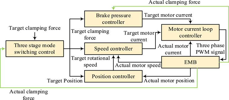
Figure 1. EMB control strategy framework.
From Figure 1, it can be seen that the EMB system adopts a position speed current three-loop control, with the goal of facilitating the formation of braking gaps to completely eliminate clamping force and prepare for the next braking. The numerical value of the clamping force determines the mode-switching control for the three stages. When the operation of the EMB is influenced by external factors, the system output will be affected, decreasing the braking effect. Therefore, to ensure that the braking effect of the EMB system is not disturbed, research proposes to integrate ADRC technology into the EMB system. When introducing ADRC into the EMB system, the working process of the EMB actuator is first analyzed. A multi-stage closed-loop control strategy framework for EMB is designed based on the working characteristics of the EMB actuator in three stages. Then, a pressure loop controller based on ADRC is designed for the pressure loop that directly affects the braking control effect of the vehicle. ADRC technology, as a new type of digital control technology, has little dependence on precise modeling of control objects and can also include possible interference factors in the total disturbance and compensate for them. The ADRC structure is shown in Figure 2.
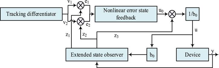
Figure 2. Self-immunity controller structure.
As shown, the tracking differentiator is responsible for extracting signals using the input characteristics of the control object. The extended state observer is responsible for tracking the system’s variables, understanding the system state in real time, and also compensating for the total disturbance. Nonlinear error state feedback is responsible for calculating the control amount using the error between the state variable and the state estimation value (Ahmed and Ali Shah, 2022; Chebbi and Briere, 2022; Yang et al., 2023). A transition process is arranged in the ADRC optimization process to address the issue of unreasonable original errors, considering the constraints of control objectives and the bearing capacity of control objects to avoid excessive tracking time or overshoot caused by large errors. At the same time, differential approximation formulas are used to approximate differentiation and address the problem of severe noise amplification in differential signals. By using differential signals, the control system can respond more sensitively to changes in the input signal and quickly adjust the control output to reduce the error between the output and the expected value. Differential control can provide faster response speed and better tracking performance, especially in situations where the input signal undergoes rapid changes. For tracking control, “faster” can be changed to “fastest,” which requires the use of a nonlinear tracking differentiator. With the transition process of tracking differentiator (TD), PID control can be achieved by utilizing the error signal and error differentiation signal of the transition process, as well as the integral signal generated based on the error signal. It is best to use nonlinear combinations for error signals, error differential signals, and integral signals generated based on error signals. Due to the disturbance estimation ability and strong anti-interference ability of ADRC, there is no need to rely on integral compensation to eliminate the influence of disturbances when calculating the controller output. Only the disturbance estimated by ESO needs to be compensated to the controller output. Considering the braking characteristics of the EMB system, it is approximated as a second-order nonlinear system, and its state equation is shown in Eq. 1.
In Eq. 1,
In Eq. 2,
In Eq. 3,
In Eq. 4,
In Eq. 5,
In Eq. 6, both
In Eq. 7,
In the longitudinal dynamics control of a vehicle, the EMB is the actuator for the adaptive cruise control and emergency braking control of the vehicle. If the completed EMB is to be applied to vehicle control, it is necessary to study the dynamic control framework of the vehicle to achieve the final closed-loop control. The longitudinal dynamics control of vehicles generally adopts a hierarchical control method, and the upper controller is responsible for obtaining decision information based on vehicle status, driver characteristics, etc., to determine the target value of speed. The lower-level controller is responsible for outputting target pressure and torque based on the vehicle status and feeding back the state information to the upper-level controller (Fang et al., 2022). The control framework of the vehicle is shown in Figure 3.
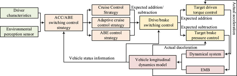
Figure 3. Control framework of vehicle longitudinal dynamics.
In Figure 3, the control system consists of an environmental sensor, adaptive cruise control, automatic emergency braking control, the target drive torque control module, the target brake pressure control module, the power system, and the EMB system. The adaptive cruise control system and automatic emergency braking control system constitute the upper control system (Sun et al., 2019; Danjuma et al., 2022). The adaptive cruise control system consists of two parts: constant speed cruise and autonomous following. The expression of the constant speed cruise controller is shown in Eq. 8.
In Eq. 8,
In Eq. 9,
In Eq. 10,
In Eq. 11,
In Eq. 12,
In Eq. 13,
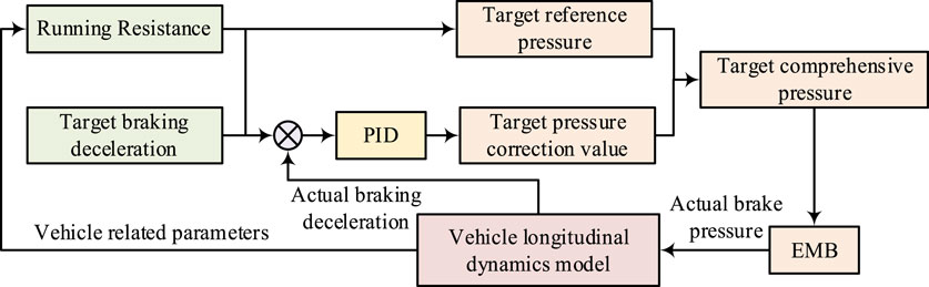
Figure 4. Target brake pressure control module structure.
From Figure 4, it can be seen that the target brake pressure control module corrects the actual brake deceleration through the PID after receiving it. The comprehensive target pressure is obtained, combined with the benchmark target pressure, and then transmitted to the EMB to achieve the conversion of actual braking pressure. The calculation formula for the benchmark target braking pressure is shown in Eq. 14.
In Eq. 14,
In Eq. 15,
In Eq. 16,
To verify ADRC-based EMB performance in the vehicle longitudinal dynamics control system, this study first tested the ADRC-based EMB system and analyzed its clamping force control effect. Then, simulation experiments were conducted on vehicle control systems based on EMB using the CarSim/Simulink joint simulation platform. In the CarSim simulation, the sprung mass of the entire vehicle is 1,110 kg, with a distance and height of 1,040 mm and 540 mm from the center of mass to the front axle, a wheelbase of 2,560 mm, a width and height of 1,661 mm and 1,535 mm respectively, and a radius of 310 mm for both the front and rear wheels. In the Simulink simulation, 1/4 of the vehicle mass is 55 kg, the initial braking speed of the wheels is 16.67 km/h, the inertia of the wheels is 0.45 kg.m2, the effective radius of the wheels is 0.298 m, and the braking coefficient of the brake is 1,661 Nm/kPa. The EMB system has a friction coefficient of 0.4 and a bilateral brake gap of 0.2 mm. The braking force control effect of ADRC and PID is shown in Figure 5.
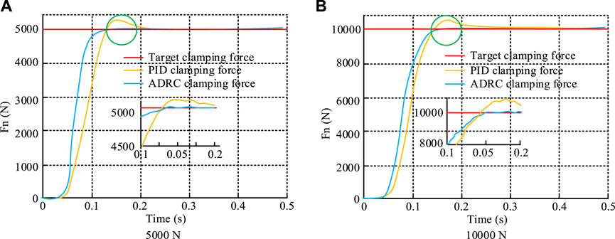
Figure 5. PID self-disturbance resistance control and braking force control effect. Note: The experimental data were jointly simulated by CarSim/Simulink. (A) 5000 N, and (B) 10,000 N.
In Figure 5A, when the target clamping force was 5000 N, the time for ADRC and PID to reach the target clamping force was 0.11 s and 0.12 s, respectively. However, there was an issue of excessive control in PID between 0.12 s and 0.2 s, while ADRC did not have this issue. From Figure 5B, when the target clamping force was 10,000 N, the time for ADRC and PID to reach the target clamping force was about 0.15 s, but there was still an issue of excessive control in PID in the 0.15–0.24 s window. It can be seen that ADRC not only can quickly respond to the target clamping force but also avoids the problem of excessive control. ADRC and PID’s anti-interference abilities are shown in Figure 6.
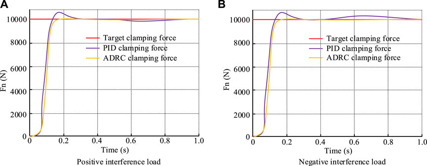
Figure 6. Anti-interference ability of self-immunity control and PID. Note: The experimental data were jointly simulated by CarSim/Simulink. (A) Positive interference load and (B) negative interference load.
Figure 6A shows that when a positive interference load was applied, the clamping force of the PID slightly decreased after being disturbed and then gradually increased. The clamping force of ADRC was still consistent with the target clamping force and did not fluctuate. As shown in Figure 6B, when a negative interference load was applied, the clamping force of the PID slightly increased and then gradually decreased to the target clamping force. However, the clamping force of ADRC did not change. It can be seen that ADRC had stronger anti-interference ability. In the joint simulation experiment of the longitudinal dynamics control system of vehicles based on the EMB system, the vehicle working conditions are divided into two types: the first is a composite working condition of constant speed cruise and autonomous following, and the second is a composite working condition of autonomous following and emergency braking. In the first operating condition, the target vehicle speed and the cruising speed were 50 km/h and 80 km/h, respectively, with a distance of 60 m between the two vehicles. At this point, Figure 7 shows the vehicle speeds and spacings.
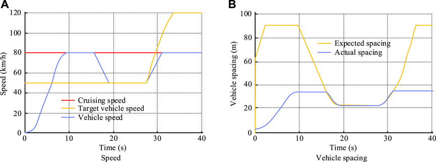
Figure 7. Speed and spacing of the local vehicle and the target vehicle. Note: The experimental data were jointly simulated by CarSim/Simulink. (A) Speed and (B) vehicle spacing.
From Fig. s 7(a) and (b), in the initial stage, the vehicle’s speed slowly increased to the set cruising speed under the action of the cruise control. At this stage, due to the initial speed of the following vehicle being smaller, the distance between the two vehicles gradually increased and eventually stabilized at approximately 90 m. When the vehicle reached cruising speed, it drove at a constant speed for a period of time. At this point, the distance between the two vehicles began to decrease due to the second vehicle’s speed increasing. When the distance between the two vehicles decreased to the expected distance, the second vehicle gradually slowed to 50 km/h. The speed of the target vehicle was followed to maintain the distance between the two vehicles. Under the first working condition, the acceleration of the vehicle and the working modes of the different modules are shown in Figure 8.
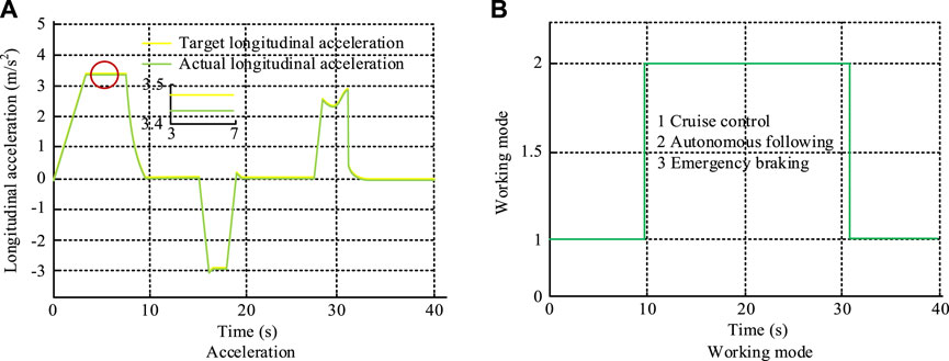
Figure 8. Acceleration of the vehicle and the working mode of different modules. Note: The experimental data were jointly simulated by CarSim/Simulink. (A) Acceleration and (B) working mode.
From Figure 8A, the actual longitudinal acceleration of the longitudinal dynamics control system based on the EMB was basically perfectly matched with the target acceleration. When the expected acceleration was 3.5 m/s2, the actual longitudinal acceleration of the vehicle was also 3.5 m/s2. In Figure 8B, under the first operating condition, the vehicle was successively in constant speed cruise, autonomous following, and constant speed cruise modes. The working time of the three modes was 10 s, 20 s, and 10 s, respectively. The driving torque and EMB braking force of this vehicle under the first operating condition are shown in Figure 9.
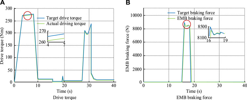
Figure 9. Driving torque and EMB braking force of this vehicle. Note: The experimental data were jointly simulated by CarSim/Simulink. (A) Drive torque and (B) EMB braking force
From Figure 9A, it can be seen that the driving torque of this vehicle basically changed with the change in acceleration. Throughout the entire process, the maximum driving torque was about 275 Nm, and the acceleration at this time was also the maximum value. In Figure 9B, the EMB braking force and the target braking force were basically perfectly fitted. When the expected braking force was 9000 N, the actual braking force of the EMB was also 9000 N. The vehicle longitudinal dynamics control system based on the EMB had a good control effect in the composite working conditions of constant speed cruise and autonomous following. In the second operating condition, the vehicle’s cruising speed was still 80 km/h, and the target vehicle’s driving speed varied between 50 km/h and 70 km/h. The distance between the two vehicles was shortened to 50 m. At this point, the driving speed and distance between the two vehicles are shown in Figure 10.
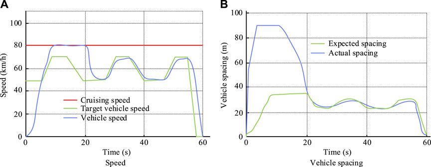
Figure 10. Driving speed and vehicle distance. Note: The experimental data were jointly simulated by CarSim/Simulink. (A) Speed and (B) vehicle spacing.
As shown in Figures 10A,B, in the second operating condition, the speed of the car gradually increases to cruising speed and the distance between the two vehicles gradually decreases. Then, as the speed of the car increased, the distance between the two cars gradually decreased. When the distance between vehicles decreased to the desired distance, the following vehicle’s speed gradually decreased and changed with the target vehicle’s speed. The acceleration and working mode of the vehicle under the second working condition are shown in Figure 11.
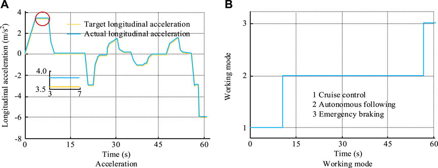
Figure 11. Acceleration and working mode of the local vehicle. Note: The experimental data were jointly simulated by CarSim/Simulink. (A) Acceleration and (B) working mode.
From Figure 11A, it can be seen that under the second operating condition, the actual acceleration of the vehicle was basically consistent with the expected acceleration. When the expected acceleration was 3.8 m/s2, the actual acceleration was also 3.8 m/s2. In Figure 11B, during the second operating condition, the vehicle was successively in cruise control, autonomous following, and emergency braking modes, with operating times of 10 s, 45 s, and 5 s, respectively. The driving torque and EMB braking force of this vehicle under the second operating condition are shown in Figure 12.
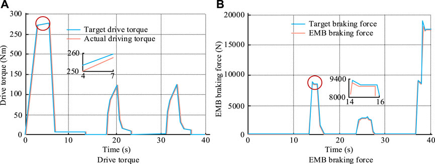
Figure 12. Driving torque and EMB braking force of this vehicle. Note: The experimental data were jointly simulated by CarSim/Simulink. (A) Drive torque and (B) EMB braking force.
From Figure 12A, it can be seen that under the second operating condition, the actual driving torque of the vehicle was basically perfectly matched with the target driving torque, with a maximum driving torque of approximately 280 Nm. Figure 12B shows that the actual braking force of EMB was basically consistent with the target braking force, with peaks of 18 kN and 19 kN, respectively. It can be seen that in the second operating condition, the vehicle longitudinal dynamics control system based on EMB still has good control effect. The control of the proposed control measurement is shown in Figure 13.
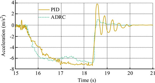
Figure 13. Brake vibration control situation. Note: The experimental data were jointly simulated by CarSim/Simulink.
Figure 13 shows that in the range of 18.5–20 s in the late PID brake control period, the acceleration fluctuates significantly because of the longitudinal vibration of the vehicle at this time. However, in the ADRC control, there was only a small fluctuation at approximately 18.5 s, and the remaining moments were stable. Although acceleration oscillations occur in both PID and ADRC control, they are caused by vehicle disturbances and not by the braking system. Under ADRC control, the acceleration oscillation caused by vehicle disturbance is well offset. It can be seen that ADRC control measurement can effectively control the longitudinal vibration of the vehicle and keep the vehicle stable.
With the increasing attention paid to traffic safety, automobile braking systems have undergone several transformations. The currently used common hydraulic brakes cannot meet the current needs of intelligent development due to their complex structure and slow response speed. Therefore, in order to meet the new braking needs of intelligent and electric vehicles, a longitudinal dynamics control system for automobiles based on ADRC-improved EMB was proposed and tested. The experimental results showed that when the target clamping force was 5000 N, the time for the ADRC and PID to reach the target clamping force was 0.11 s and 0.12 s, respectively. However, there was an issue of excessive control in the PID between 0.12 s and 0.2 s, while the ADRC did not have this issue. Regardless of whether positive or negative interference was applied, the clamping force of ADRC did not fluctuate, while the clamping force of PID changed under the disturbance. In joint simulation testing, when the expected acceleration was 3.8 m/s2, the actual acceleration was also 3.8 m/s2. When the expected braking force was 9000 N, the actual braking force of the EMB was also 9000 N. Regardless of the operating conditions, the actual acceleration, actual driving torque, and EMB braking force of the improved EMB-based vehicle control system were consistent with the expected values. The above results indicate that the response time of the EMB vehicle longitudinal dynamics control system is short, and the braking effect is good and can achieve the expected value. Although the longitudinal dynamics control state of EMB vehicles proposed in the study performed well in joint simulation experiments, only simple operating conditions between vehicles were considered in the testing, without considering complex situations such as sudden pedestrian intrusion or vehicle congestion. Therefore, in the future, it is necessary to optimize the EMB to cope with more complex operating conditions.
The original contributions presented in the study are included in the article/supplementary material; further inquiries can be directed to the corresponding author.
XW: data curation, formal analysis, methodology, writing–original draft, and writing–review and editing. RH: data curation, validation, and writing–review and editing. HG: conceptualization, resources, and writing–review and editing. MC: conceptualization, resources, and writing–review and editing.
The author(s) declare that no financial support was received for the research, authorship, and/or publication of this article.
Author RH was employed by CRRC Qishuyan Co., Ltd.
The remaining authors declare that the research was conducted in the absence of any commercial or financial relationships that could be construed as a potential conflict of interest.
All claims expressed in this article are solely those of the authors and do not necessarily represent those of their affiliated organizations, or those of the publisher, the editors, and the reviewers. Any product that may be evaluated in this article, or claim that may be made by its manufacturer, is not guaranteed or endorsed by the publisher.
Ahmed, N., and Ali Shah, S. A. (2022). Adaptive output-feedback robust active disturbance rejection control for uncertain quadrotor with unknown disturbances. Eng. Comput. Int. J. Computer-Aided Eng. Softw. 39 (4), 1473–1491. doi:10.1108/EC-02-2021-0098
Chebbi, J., and Briere, Y. (2022). Robust active disturbance rejection control for systems with internal uncertainties: multirotor UAV application. J. Field Robotics 39 (4), 426–456. doi:10.1002/rob.22058
Danjuma, M. U., Yusuf, B., and Yusuf, I. (2022). Reliability, availability, maintainability, and dependability analysis of cold standby series-parallel system. J. Comput. Cognitive Eng. 1 (4), 193–200. doi:10.47852/bonviewJCCE2202144
Devika, K. B., Sridhar, N., Patil, H., and Subramanian, S. C. (2021). Delay compensated pneumatic brake controller for heavy road vehicle active safety systems. Proc. Institution Mech. Eng. Part C J. Mech. Eng. Sci. 235 (13), 2333–2346. doi:10.1177/0954406220952822
Fang, Y., Luo, B., Zhao, T., He, D., Jiang, B., and Liu, Q. (2022). ST-SIGMA: spatio-temporal semantics and interaction graph aggregation for multi-agent perception and trajectory forecasting. JCAAI Trans. Intell. Technol. 7 (4), 744–757. doi:10.1049/cit2.12145
Gao, Y., Huo, X., Ma, K., and Zhao, H. (2020). Modified model-compensation ADRC controller and its application in PMSM current loop. Int. J. Model. Identif. Control 35 (2), 140–150. doi:10.1504/IJMIC.2020.113716
Heydrich, M., Ricciardi, V., Ivanov, V., Mazzoni, M., Augsburg, K., Buh, J., et al. (2021). Integrated braking control for electric vehicles with in-wheel propulsion and fully decoupled brake-by-wire system. Vehicles 3 (2), 145–161. doi:10.3390/vehicles3020009
Huang, S., Bao, J., Ge, S., Yin, Y., and Liu, T. (2019). Design of a frictional–electromagnetic compound disk brake for automotives. Proc. Institution Mech. Eng. Part D J. Automob. Eng. 234 (4), 1113–1122. doi:10.1177/0954407019864210
Jin, H., Xu, H., and Wang, S. (2022). Design and test of electromechanical disc brake controller for mine hoist. Meas. Control J. Inst. Meas. Control 55 (3/4), 146–154. doi:10.1177/00202940221091270
Jing, Z., and He, R. (2019). Electronic structural improvement and experimental verification of a tractor-semitrailer air brake system. Proc. Institution Mech. Eng. Part D J. Automob. Eng. 234 (8), 2154–2161. doi:10.1177/0954407019899794
Ma, X., Qin, Y., Kong, D., Liu, D., and Wang, C. (2021). Adaptive and ADRC information fusion method for high speed train braking system. EAI Endorsed Trans. Scalable Inf. Syst. 9 (34), 171248. doi:10.4108/eai.6-10-2021.171248
Muhammed, A., Yazan, W., and Alexander, G. I. (2022). Linear-control vs. ADRC for automatic management of the handling-comfort contradiction of a quarter-car system, Int. J. Heavy Veh. Syst. (IJHVS) 29 (2), 145–162. doi:10.1504/IJHVS.2022.125361
Parkash, A., and Swarup, A. (2022). Development of autonomous vehicle lateral control using time-varying asymmetric barrier Lyapunov function via ADRC approach. Proc. Institution Mech. Eng. Part I, J. Syst. Control Eng. 236 (9), 1679–1691. doi:10.1177/09596518221103040
Subramaniyam, K. V., and Subramanian, S. C. (2021). Electrified vehicle wheel slip control using responsiveness of regenerative braking. IEEE Trans. Veh. Technol. 70 (4), 3208–3217. doi:10.1109/TVT.2021.3066095
Sun, X., Zhang, H., Cai, Y., Wang, S., and Chen, L. (2019). Hybrid modeling and predictive control of intelligent vehicle longitudinal velocity considering nonlinear tire dynamics. Nonlinear Dyn. 97 (2), 1051–1066. doi:10.1007/s11071-019-05030-5
Weng, J., Tian, C., Wu, M., and Chen, M. (2021). Coupled rigid-flexible modelling and dynamic characteristic analysis of electromechanical brake (EMB) units on trains. Proc. Institution Mech. Eng. Part F J. Rail Rapid Transit 235 (6), 700–712. doi:10.1177/0954409720957542
Wu, M., Ma, T., Tian, C., Yang, J., and Chen, M. (2019). Discussion on development trend of train braking technology. China Railw. Sci. 40 (1), 134–144. doi:10.3969/j.issn.1001-4632.2019.01.18
Xu, F., and Cho, C. (2022). A novel electronic wedge brake based on active disturbance rejection control. Energies 15 (14), 5096. doi:10.3390/en15145096
Yang, K., Wang, J., Tan, D., Zhang, X., and Liu, J. (2019). Parameter matching and braking performance advantage study for all-electric independent driving and braking electric vehicle with four wheels. Int. J. Electr. Hybrid Veh. 11 (2), 106–126. doi:10.1504/IJEHV.2019.099995
Keywords: control strategy, electronic mechanical braking, longitudinal dynamics, multi-stage control, self-disturbance rejection control
Citation: Wu X, He R, Ge H and Chen M (2024) Electronic mechanical braking system executive mechanism design, calculation, and modeling based on dynamic control. Front. Mech. Eng 10:1368683. doi: 10.3389/fmech.2024.1368683
Received: 11 January 2024; Accepted: 01 April 2024;
Published: 14 May 2024.
Edited by:
Renato Vidoni, Free University of Bozen-Bolzano, ItalyReviewed by:
Ján Dižo, University of Žilina, SlovakiaCopyright © 2024 Wu, He, Ge and Chen. This is an open-access article distributed under the terms of the Creative Commons Attribution License (CC BY). The use, distribution or reproduction in other forums is permitted, provided the original author(s) and the copyright owner(s) are credited and that the original publication in this journal is cited, in accordance with accepted academic practice. No use, distribution or reproduction is permitted which does not comply with these terms.
*Correspondence: Xinping Wu, eGlucGluZ3d1MDcwN0AxMjYuY29t
Disclaimer: All claims expressed in this article are solely those of the authors and do not necessarily represent those of their affiliated organizations, or those of the publisher, the editors and the reviewers. Any product that may be evaluated in this article or claim that may be made by its manufacturer is not guaranteed or endorsed by the publisher.
Research integrity at Frontiers
Learn more about the work of our research integrity team to safeguard the quality of each article we publish.