 Mahesh K. Gaikwad1
 Savita U. Shinde2
 Mithul J. Naidu3Tushar A. Jadhav4Rakesh Kumar5,6
 Sachin Salunkhe7,8*
 Robert Cep9
 Emad Abouel Nasr10
- 1Department of Mechanical Engineering, Jayawantrao Sawant College of Engineering, Savitribai Phule Pune University, Pune, Maharashtra, India
- 2Department of Mechanical Engineering, MIT School of Engineering and Sciences, MITADT University, Pune, Maharashtra, India
- 3Department of Mechanical Engineering, Smt. Kashibai Navale College of Engineering, Savitribai Phule Pune University, Pune, India
- 4Department of Mechanical Engineering, Sinhagad College of Engineering, Savitribai Phule Pune University, Pune, India
- 5Department of Mechanical Engineering, Faculty of Engineering and Technology, Jain (Deemed-to-be) University, Bengaluru, Karnataka, India
- 6Department of Mechanical Engineering, Vivekananda Global University, Jaipur, Rajasthan, India
- 7Department of Biosciences, Saveetha School of Engineering, Saveetha Institute of Medical and Technical Sciences, Chennai, India
- 8Gazi University Faculty of Engineering, Department of Mechanical Engineering, Maltepe, Türkiye
- 9Department of Machining, Assembly and Engineering Metrology, Faculty of Mechanical Engineering, VSB-Technical University of Ostrava, Ostrava, Czechia
- 10Department of Industrial Engineering, College of Engineering, King Saud University, Riyadh, Saudi Arabia
This paper focuses on the numerical and experimental investigation of the small-scale power generator. The travelling wave thermoacoustic power generator is numerically analyzed and experimentally tested. The cyclic analysis is used to carry out numerical analysis of the power generator. The system is operated on atmospheric pressure, which allows the manufacturing of an acoustic feedback loop using Polyvinyl chloride piping. The acoustic power generated inside the generator is harnessed by the low-cost linear alternator, i.e., loudspeaker. The effect of regenerator wire mesh on performance of the power generator is numerically analyzed and validated experimentally. The numerical analysis identifies the temperature variation, pressure fluctuation, volume flow rate inside the system, and acoustic power distribution. The maximum electric power experimentally generated by the small-scale power generator is around 45 W with overall efficiency 8.30%. The alternator generates the maximum electric power at the optimum location, i.e. 2.30 m away from the engine core.
1 Introduction
The utilization of low-temperature heat sources, such as solar energy and industrial waste heat sources, has received a lot of attention due to concerns about global warming and the depletion of fossil fuels. Various technologies have been invented at varying scales for applications related to energy recovery. The acoustic counterpart of the traditional Stirling engine is the traveling-wave thermoacoustic engine. It converts thermal energy to acoustic energy by means of a Stirling-like thermodynamic cycle that is achieved through the use of a compact acoustic network. In this technology the oscillating heat flow occurs when there are temperature gradient present in the engine. In the past few decades, traveling-wave thermoacoustic engines received significant attention owing to their unique characteristics. Nikolaus Rott’s (1980) has developed a foundation theory for the linear approximation of the continuity, momentum, and energy equations. The author also analysed the flow of fluid and the heat transfer phenomenon inside the thermoacoustics. Swift G.W. (1988) has used linear theory to analyze the thermoacoustic engine. In this theory all oscillating variables are assumed at angular velocity ω. Swift and Ward (1996) have developed a code for thermoacoustic system analysis, DeltaEC, i.e., Design Environment for Low-amplitude Thermoacoustic Energy Conservation. In this analysis simulation of porous regenerator, turbulence losses, losses due to change in cross section area, and entrance-exit loss can be analysed. The benefits of both a linear alternator and a thermoacoustic engine are combined in a thermoacoustic generator, which produces electricity from low-temperature heat sources with excellent reliability and effectiveness. (S. Backhaus et al., 2004; Petach et al., 2004). When connected to thermoacoustic engines, audio loudspeakers typically have low acoustic impedance, which presents new design issues and concerns. Yu et al. (2012) have carefully examined these problems both experimentally and theoretically. An audio loudspeaker was installed as an alternator in the looped-tube traveling-wave thermoacoustic engine to create a low-cost thermoacoustic electric generator prototype. In addition, Chen et al. (2012) described the development of inexpensive, two-stage traveling-wave thermoacoustic generators that use cooking stove waste heat energy to produce electricity. The thermoacoustic generator powered by a propane stove generated about 15 W of electricity by using an audio loudspeaker as the alternator. Saha et al. (2012) have theoretically analysed the double and multiple coil Halbach array alternator structures. The reliability factor of the alternator suspension has major impact on performance, according to the measured results of the tested prototype, and a maximum acoustic-electrical efficiency of 57% was determined. Huifang Kang et al. (2015) have introduced the novel concept for installation of loudspeaker as linear alternator to develop electric power. One alternator was placed at the end of a branched stub, and the other was placed within the engine loop to suppress the Geoden acoustic streaming. Kalid O. A. et al. (2017) have numerically analysed the side branch mounted alternator engine using DeltaEC code. The results obtained from numerical analysis indicated that electric power obtained is about 18.4 W, where experimentally it get 17.8 W with overall efficiency 1.9%. Baiman Chen et al. (2017) have analysed thermoacoustic engine using DeltaEC code. The analysis showed that regenerator produces about 1868 W acoustic power at 550 K temperature difference. Shendage et al. (2017) have analysed and optimized design parameters of the Beta type Stirling engine with rhombic drive using cyclic analysis. It provides the ideal power output and heat input while taking into account overlapping volume and breaks down the thermodynamic cyclic analysis. Ahmed et al. (2018) have experimentally tested two stage engine using push pull type linear alternator for effective utilization of acoustic impedance. Krishna Gaikwad et al. (2018) have discussed in detail the design procedure of different parts of the thermoacoustic engine. To reduce the experimentation time different regenerator can(s) were used. The secondary heat exchanger is modified to enhance heat transfer rate. Krishna Gaikwad et al. (2019) have numerically analysed travelling wave thermoacoustic engine using CFD tool. Three working fluids air, hydrogen and helium were tested in this analysis. Yang et al. (2019) have performed experiments on 3-stage thermoacoustic engine using five R-C variable loads to measure generated acoustic power. The setup has thermal efficiency of about 9.6% at 1950 hot exchanger temperature. Krishna Gaikwad et al. (2021) have numerically and experimentally analysed thermoacoustic engine using different wire mesh. The numerical analysis generates power about 50 W. Saechan and Dhuchakallaya, (2020) have analysed the influence of stub position and its length in the looped tube thermoacoustic engine. The engine operated at 65 Hz frequency using air at atmospheric pressure. Liu et al. (2020) have analysed the ability of three stage looped thermoacoustic engine for effective thermoacoustic conversion and acoustic power transmission using CFD tool. The suggested unequal-radius resonance tubes assist in the implementation of impedance matching and acoustic power amplification. Widyaparaga et al. (2020) have numerically analysed the two thermoacoustic engine adjusting the phase lag and acoustic energy. The analysis showed acoustic power flow in negative direction for phase lag 300 and 600 and in positive direction for 300 and 330. Mahesh and Patil, (2021) have numerically analysed travelling wave thermoacoustic engine considering wall Prandtl number as 0.85. In analysis six monitoring points are considered to analyze generation and transmission of acoustic wave. Daming Sun et al. (2021) have investigate the working mechanism of thermoacoustic engine with the unsteady onset process as the primary focus using a unique nonlinear one dimensional unsteady model. The computational results showed that the acoustic oscillations in the transient onset process is greatly enhanced by thermal conduction. Vorotnikov et al. (2022) have created a mathematical equation for calculating the gas averaged velocity. This analysis allows for the calculation of gas averaged velocity and power produced by using the acoustic impedance of the engine core and the dynamic pressure distribution. Dhuchakallaya and Saechan, (2022) have investigated the impact of an in-line phase-adjuster on a thermoacoustic Stirling heat engine’s energy conversion efficiency. The authors introduced the phase adjuster at the end of resonance tube. Zilong Jia et al. (2022) have developed free-piston Stirling generator simulator using SAGE software for acoustic impedance matching. The setup produced electrical power about 1040 W with overall efficiency of about 36.2%. Liu et al. (2023) have examined and optimized the relationship between the resonance tube structure and the hot-side heat exchanger temperature using response surface methodology for 3-stage engine. The author also observed that increasing the geometry of resonance tube and hot side temperature enhances the generation of acoustic power. Ahmed and Jaworski, (2023) have investigated a novel thermoacoustic engine without using resonator tube. This engine developed electric power at about 120.5 W with efficiency 20.5%.
In the present work novel technique, cyclic analysis is used for thermodynamic assessment of a travelling wave thermoacoustic engine. In addition to this loudspeaker as linear alternator is used and analysed with the help of cyclic analysis. The ultimate objective of this research is to advance the development of low-cost thermoacoustic generators by demonstrating the potential of these devices further. Further, the numerical analysis determines the temperature variation, pressure fluctuation, volume flow rate inside the thermoacoustic engine and acoustic power distribution throughout the engine loop. Then experimentally the electric power has determined for different mesh for different temperature gradients for different locations of linear alternator.
2 Numerical analysis of thermoacoustic power generator using cyclic analysis
In the numerical analysis of the travelling wave thermoacoustic generator the cyclic analysis plays an important role. The assumptions used in this cyclic analysis are fairly realistic and mimic the real-world circumstances found in travelling wave thermo-acoustic engine. All individual losses that are known to exist, such as the pressure drop in hot and cold heat exchangers, the loss from temperature swings, the ineffectiveness loss in the regenerator, and the conduction loss from the wire mesh matrix in the regenerator, are estimated. The analysis has been adjusted to take into account the detailed heat losses and pressure drop inside the engine’s expansion and compression space for non-sinusoidal motion. All of these losses are considered to be independent of one another and therefore independently calculated. According to the analysis, the energy flow inside the engine is one-dimensional along a direction of gas oscillation, and that extends from one terminal to the next.
The analysis consists of the subsequent crucial steps:
i) to analyze fluctuations in pressure and volume across a specific period of time.
ii) to determine the air’s mass in the specific intervals at the compression and expansion spaces.
iii) determining the working fluid’s overall mass and its fraction in each working space.
iv) to obtain the mass flow rate for a specific working space by knowing the change in mass over a given interval.
v) understanding volume and pressure variations for different work environments
The analysis identifies the temperature variation, pressure amplitude variation, volume flow rate, and acoustic power generated along the entire loop of the travelling wave thermoacoustic generator. In the present thermoacoustic power generator setup air at atmospheric pressure is used as working fluid. The block diagram of numerical analysis and the laboratory setup is shown in Figures 1A, B respectively.
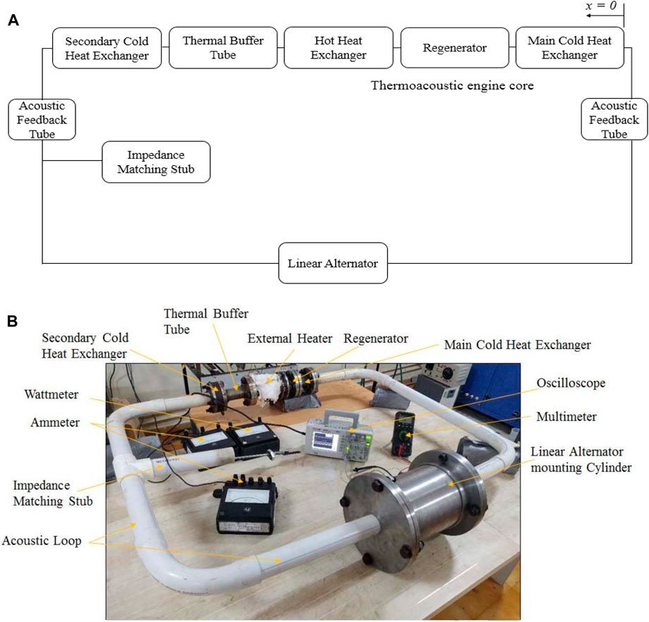
FIGURE 1. (A) The block diagram of the segments in the numerical analysis of travelling wave thermo-acoustic system (B) The laboratory setup of small scale travelling wave thermoacoustic power generator.
Moreover using air at atmospheric pressure also reduces the problem of leakages and need of high pressure seals. PVC (Polyvinyl chloride) pipe is used for acoustic loop of the power generator to reduce the cost of setup and boundary layer phenomena. Use of PVC material also reduces friction and viscous losses of gas in contact with the acoustic loop walls as compared to metal surfaces. The main cold heat exchanger, regenerator, hot heat exchanger, thermal buffer tubes are made with SS347 for more reliable design and low maintenance cost. Commercially available loud speaker is used as linear alternator to extract the electricity from the acoustic or pressure waves which are produced inside the thermoacoustic engine. At the start of analysis volume of air occupied in cold heat exchanger, hot heat exchanger and regenerator is calculated using Eqs 1–3 respectively (Shendage, Kedare, and Bapat, 2017).
In cyclic analysis the temperature inside the regenerator varies logarithmically along the length of the regenerator. At this two ends of regenerator calculated using Eq. 4
To calculate volume inside the cycle for the particular instant in cold and hot heat exchanger using Eqs 5, 6 (Shendage, Kedare, and Bapat, 2017),
The mass of air present inside the core of the generator is calculated by considering Eq. 7
At the start of the cyclic analysis the total mass of air is unknown, so considering component M
From Eq. 8 starting pressure p(1) calculated by calculating all variables. The complete cycle is split into 12 intervals for ease of the analysis. Here, hot heat exchanger temperature after first interval, i.e., TE(2) is calculated considering TE(1), p(1), and an assumed value of p(2).
For adiabatic compression, assuming
Here, value of TC (2) is calculated for the considered value of p(2).
Eq. 11 (Martini W., 1978), used to determine the generator mean pressure, Pm
where,
For each interval of cycle, Eq. 13, determines the working fluid mass fraction of the total mass of the gas in hot heat exchanger (FE), cold heat exchanger (FC), and regenerator (FR).
The mass flow rates in hot heat exchanger (
From Eq. 16 computed the ideal power acoustic power generated (Martini, 1978),
The generated acoustic power transmitted to the linear alternator through feedback pipe can be computed using the time average of the dot product of the dynamic pressure and the piston velocity,
The average acoustic power, supplied by an alternator moving piston of area Aalt is given by:
Thus,
The loss analysis in the travelling wave thermoacoustic engine and its effect was discussed in a prior article (Mahesh and Patil, 2020).
2.1 Numerical analysis of loudspeaker as linear alternator
An alternator’s transduction efficiency is only influenced by its individual electrical and mechanical characteristics and is not influenced by the acoustic field inside the thermoacoustic engine. In order to maximize thermodynamic conversion efficiency and minimize losses from acoustic power transmission, the entire system’s design should be centered on optimizing the acoustic field within the thermoacoustic engine. However, when acoustic waves travel through the diaphragm, the alternator results in significant pressure drops and, consequently, abrupt drops in acoustic impedance. Usually, a branch stub is needed for compensating this effect. The effective area of loudspeaker moving diaphragm S has moving due to the oscillating wave acoustic pressure. The total moving mass Mm include mass of diaphragm and mass of coil. The stiffness of loudspeaker and resistance of coil are shown by K and R respectively. The resistance and inductance of electric coil are shown by Le and Re respectively. The pressure drop and volumetric velocity at the diaphragm are represented by Δp and U1 respectively.
All parameters are assuming linear and independent from frequency, also neglecting losses due to hysteresis, the model shown in Figure 2 can be characterized approximately by the following linear equations, (Kang, et al., 2015),
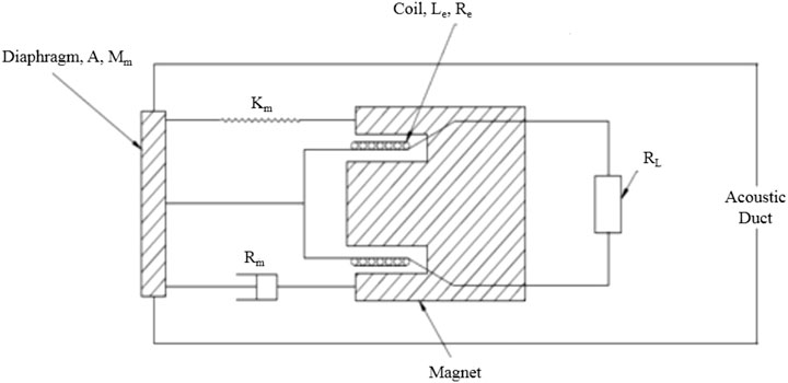
FIGURE 2. Schematic of the loudspeaker.
The acoustic power supplied to alternator PAlt, in is given as
In Eq. 22
However, the power which oscillates the alternator is,
The alternator utilizes the generated acoustic power PAlt is
The load resistor absorbed some electric power which calculated as,
In Eq. 25
The efficiency from acoustic power to electric power can be computed as,
Further substitute the Eqs 20, 21 into Eq. 24 leads to
From Eq. 27 not considering the effect of coil inductance, the load resister can extract electric power as (Kang et al., 2015),
The alternator can extract maximum power, when Re is equal to RL,
In this current work the loudspeaker has product ω⋅Le is very less than Re or RL. So substituting Eqs 27, 28 into the Eq. 26, the approximate efficiency is,
The maximum efficiency obtained when Re = RL
The maximum electric power calculated using (Kang et al., 2015)
From Eq. 33 the maximum electric power generated is proportional to
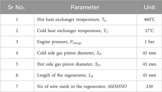
TABLE 1. Operating and geometric parameter for analysis.
2.2 Result and discussion on cyclic analysis
The above-mentioned simplified model offers an extremely helpful qualitative comprehension of the behaviour of the thermoacoustic power generator taken into consideration in this paper. This section’s discussion of the simulation results is predicated on the prototype’s final design, the details of which are provided in the following section. This will enable comparisons between the simulations and experiments in order to validate the model. To make the current prototype’s construction and operation simpler, atmospheric air is used as the working gas. The increased frequency has the effect of increasing the ideal acoustic power produced. At the same time losses in the thermoacoustic engine may increase drastically than the ideal acoustic power. Figure 3 represents the influence of the frequency on the generation of the acoustic power in the thermoacoustic engine. The thermoacoustic engine delivers the maximum acoustic power at around 78 Hz.
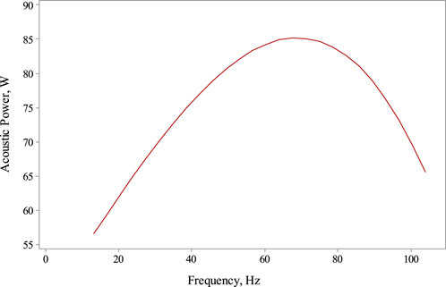
FIGURE 3. Effect of frequency on the generation of the acoustic power.
The variation of the air temperature in the cold heat exchanger, hot heat exchanger, and regenerator space is shown in Figure 4. The temperature within the cold and hot heat exchanger spaces rises as the total volume decreases before volume increasing once again. As the volume increases, the gas cools due to expansion, and the temperature in the compression and expansion spaces decreases.
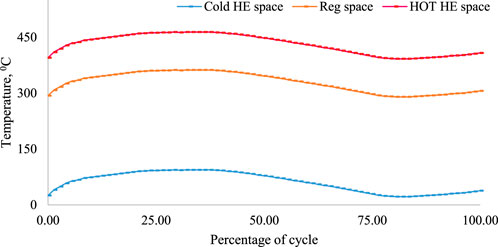
FIGURE 4. Temperature variation in the cold heat exchanger space, hot heat exchanger space, and regenerator space.
The pressure amplitude distribution over the 4.13 m long thermoacoustic engine loop is shown in Figure 5. The pressure in the engine loop has two maximum and two minimum amplitudes, as well as three sudden drops. One is due to wire mesh screens at regenerator space, second at the stub section of engine and third one is at alternator area. There is a significant amount of acoustic power extracted by the linear alternator. The regenerator RReg, flow resistance causes the first pressure drop. The second is induced by an area change at the stub section RStub, and third is brought on by acoustic resistance RAlt initiated by the speaker. The alternator is positioned in the vicinity of the highest pressure amplitude. All other portions of the engine loop experience smooth pressure amplitude variations.
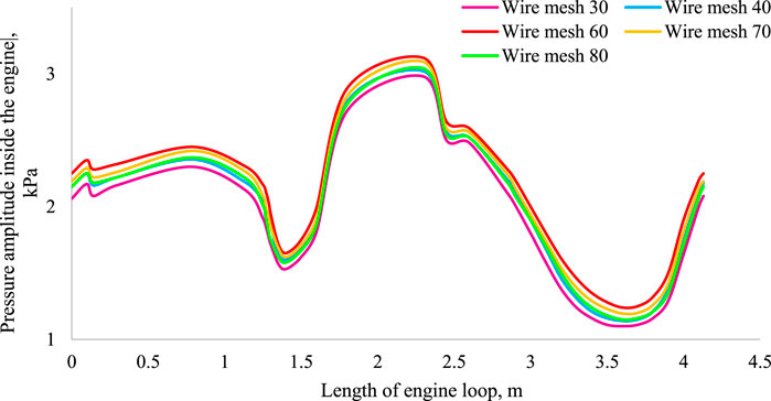
FIGURE 5. Pressure amplitude along engine loop.
Figure 6 illustrates the variation of volumetric velocity along the thermoacoustic engine’s acoustic loop. Along the length of the engine, this graph shows three maxima and three minima. The main cold heat exchanger has the minimum volumetric velocity, followed by the stub section and at an alternator it’s very low where it extracts velocity. Low volumetric velocity inside the regenerator minimizes large viscous loss. Due to the considerable temperature gradient, the volumetric velocity significantly increases along with the regenerator. The volumetric velocity is seen to drastically increase at the stub position. Smooth fluctuations in volumetric velocity occur across the thermoacoustic engine’s various areas.
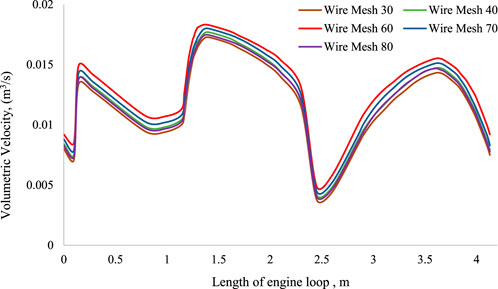
FIGURE 6. Volumetric velocity along engine loop.
The acoustic power distribution along engine loop for various wire mesh screens is illustrated in Figure 7. In comparison to other wire mesh, the wire mesh 60 strands/inch performs well. According to the analysis, the main cold heat exchanger receives about 34 W of acoustic power, from which it dissipates 3.6 W, and reaming 30.4 W transferred the cold end of the regenerator. The amplified acoustic power level coming from the regenerator’s hot end is approximately 109.6 W, which represents an increase in the acoustic power level inside the regenerator. 7.7 W of acoustic power is dissipated in the region between the hot heat exchanger and thermal buffer tube. Then, approximately 12.5 W of acoustic power was dissipated in the stub area. The alternator harnessed about 87.3 W of acoustic power from total supplied power. The acoustic feedback loop dissipates about 3.08 W acoustic power. The cyclic study reveals that the alternator produces 50.22 W of electrical power. The thermal power supplied to engine through hot heat exchanger is around 540 W. The results obtained from the cyclic analysis were around 16.66% for the thermal to acoustic efficiency (T-A), 57.52% for the acoustic to electric efficiency (A-E), and 9.3% for the thermal to electric efficiency (T-E).
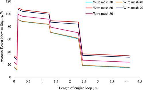
FIGURE 7. Acoustic power along engine loop.
Five stainless steel wire mesh can(s) with wire mesh numbers 30, 40, 60, 70, and 80 strands per inch are tested within the regenerator to evaluate the performance of the thermoacoustic engine. The numerical analysis results of the regenerator temperature gradient and generated electricity are plotted on the graph as shown in Figure 8. When the temperature gradient across the regenerator reaches a specific threshold value, the acoustic fluctuations begins. For mesh size 30 strands/inch, the oscillations began at nearly 206°C. The pressure drop and prolonged acoustic oscillation occurred due to fine meshing which creates obstacle to acoustic wave (Fujita et al., 1983). As a result, oscillations started for fine mesh with 80 strands/inch at a temperature of approximately 282°C. The numerical results showed that maximum electric power generated for wire mesh 60 stands/inch is about 50.22W as compared to other wire mesh. Table 2 represents the electric power generated for different wire mesh.
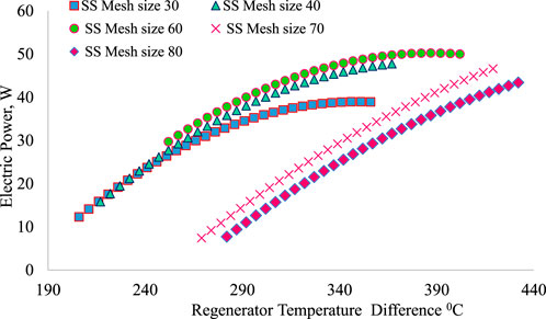
FIGURE 8. Numerical analysis result of electric power generated for wire mesh.
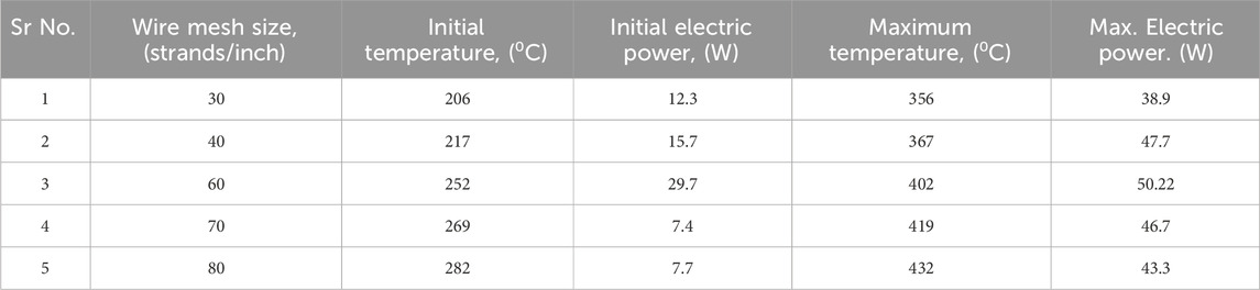
TABLE 2. Electric power generated from the analysis for different wire mesh at temperature range.
3 Experimental setup
A thermoacoustic generator prototype has been built based on the current concept and the comprehensive simulation outcomes. The travelling wave thermoacoustic engine has been built using acoustic feedback loop. The engine has a looped type acoustic structure and is constructed of 2 inch diameter PVC (Polyvinyl chloride) pipe with 900 bends. The connecting flanges are ASME grade 316L and class 300. The cross-sectional area of the acoustic loop remains constant during its entire length. The system was developed for atmospheric pressure and electric heater is used to supply heat. The alternator and thermoacoustic engine core are the two main parts of the engine. The indirect thermal contact between two flowing streams, i.e., cold water and air, is provided by a single pass counter flow main cold heat exchanger.
The cold heat exchanger designed such way that it causes a minimum pressure drop in either flowing streams. The main cold heat exchanger uses water at room temperature to remove heat from the working fluid. The air is passing through the 2 mm diameter forty copper tubes which are surrounded by water jacket. The main cold heat exchanger is constructed of SA 347 and has a length of 98 mm, an external diameter of 60.3 mm, and an internal diameter of 42.9 mm. Its porosity is 8.7%. With an external diameter of 48.8 mm, the regenerator body is constructed from SA 347. The regenerator internal diameter in the present thermoacoustic engine is larger than the other components to account for acoustic impedance (Saechan and Jaworski, 2018). Additionally, regenerator length is altered experimentally by employing various wire mesh can(s), which significantly cuts down the time needed for engine disassembly and installation (Mahesh and Patil, 2018). A 45 mm long regenerator made up of the 230 discs is assembled and placed within a stainless steel container. The regenerator has a hydraulic radius of 0.0871 mm and a porosity of 65%. The thermoacoustic engine is powered by using a 0.6 kW electric heater. In actual use, it delivers 540 W power due to some manufacturing defects or heat losses. The hot heat exchanger has porosity of about 20.1% and it constructed using stainless steel 347 and has internal and external diameters of 42.9 mm and 60.3 mm, respectively, and a length of 150 mm. The thermal buffer tube’s first section is an 80 mm long straight pipe with a 42.9 mm internal and 60.3 mm external diameter. To prevent Rayleigh streaming the next portion of tube is made with an internal taper of 2.60 (Backhaus S. and Swift G.W., 2000). The stainless steel cylinder with an internal diameter of 98 mm and an outer diameter of 152 mm is brazed to the copper pipe with an internal diameter of 42.9 mm and a thickness of 8 mm to manufacture the secondary cold heat exchanger. The engine is built to operate with air that is at atmospheric pressure. The average engine pressure variation, which corresponds to the acoustic pressure, is often less than 0.1 bar. Therefore, the acoustic feedback loop is built using PVC pipes. When compared to metal surfaces, the use of PVC material for acoustic loops also reduces friction and viscous gas losses in contact with acoustic loop walls. According to the computed frequency up to 78 Hz by the cyclic analysis, the current research work has chosen an acoustic loop with a total length of 4.13 m (Saechan and Jaworski, 2018). In order to change the impedance between the linear alternator and the thermoacoustic engine, a stub section is inserted to the acoustic loop system. To modify the impedance, a solid piston fits inside an extended PVC pipe at the T-section (stub section) of the acoustic loop system. To extract the acoustic power produced and amplified inside the thermo-acoustic engine, the alternator is mounted inside an M.S. cylinder with a diameter of 210 mm and a length of 300 mm. In order to harvest the acoustic energy produced inside the thermoacoustic engine and transform it into electrical energy, the audio loudspeaker is used as a linear alternator as shown in Figure 9.
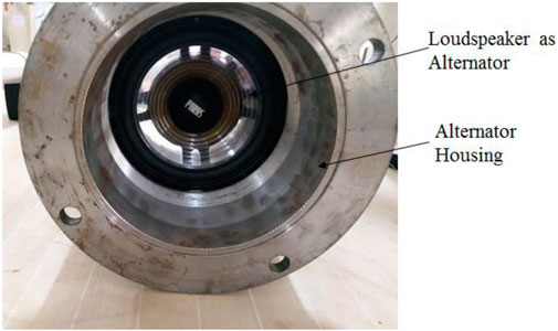
FIGURE 9. Mounting arrangement for loud speaker.
The conventional 50 W audio loudspeaker 5-inch subwoofer as linear alternator is utilized due to market availability. Table 3 indicates the instrumentation specifications of thermo-acoustic engine and Table 4 provides a comparison of various loudspeakers and their specifications. The load resistance is set to 9 Ω to extract electrical power from the alternator (loudspeaker). Voltmeters (resolution 0.001 V) and ammeters (resolution 0.01 A) are used to measure the voltage and current.
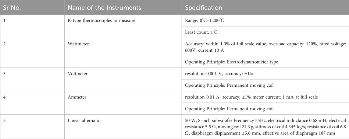
TABLE 3. Instrumentation specifications of thermo-acoustic engine.
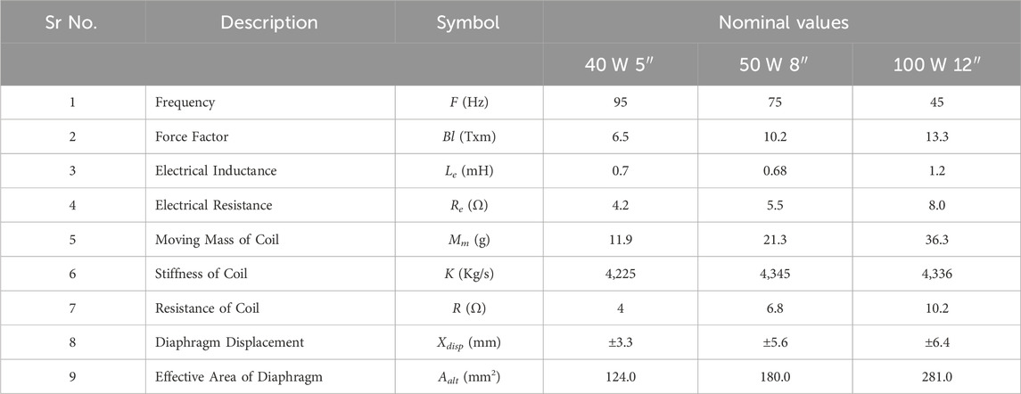
TABLE 4. Loud speakers specifications.
4 Results and discussion
The thermoacoustic engine is operate from ambient temperature in all experimental testing. Maximum temperature of the hot heat exchanger is kept at about 460°C. For all tested wire mesh, the output acoustic power generated is lower than the predicted one because of convective heat loss from the hot heat exchanger. The impedance matching stub is adjusted manually at 200 mm from T-section of loop which supplied the maximum acoustic power to the linear alternator.
4.1 Variation of regenerator temperature
Four K-type thermocouples are used to measure the internal temperature of the thermoacoustic engine. One at the hot heat exchanger and three within the regenerator section. The oscillation of gas parcels enhances the rate of heat transfer from the hot heat exchanger to the regenerator after the onset temperature is reached in the regenerator section for different wire mesh. The temperature inside the regenerator becomes almost steady when the acoustic oscillations achieve equilibrium, as illustrated in Figure 10.
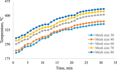
FIGURE 10. Regenerator temperature variation for different wire mesh.
4.2 Linear alternator optimum location
The optimum location for the linear alternator along the looped tube thermoacoustic engine is identified after analyzing the five different locations. With x = 0, the main cold heat exchanger provides as the starting point for the layout of other components within the thermoacoustic engine loop. The analysis identifies a computed frequency of about 78 Hz from which the acoustic loop length is selected up to 4.13 m. In Figure 11, the linear alternator’s position is plotted against the amount of electricity produced at a frequency of 78 Hz. Results obtained for maintaining hot heat exchanger temperature 460°C the maximum electric power generated of about 44.9 W location x = 2.32 m.
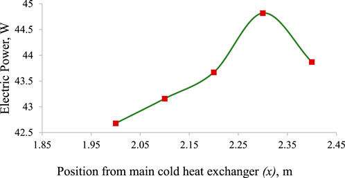
FIGURE 11. Optimum location of alternator in acoustic loop vs. generated electric power.
4.3 Electric power generated inside the engine
The results of the numerical analysis and experimental testing of the electric power produced for the temperature gradient along the regenerator are presented in Figure 8; Figure 12. The result indicates the linear relation in between it (Abduljalil et al., 2011).
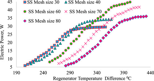
FIGURE 12. Experimental electric power generated for different wire mesh sizes.
The mesh with 60 strands/inch produces the maximum electric power of about 44.9 W, with the overall efficiency of about 8.3% higher than that of the other examined meshes. As the mesh size advances from 30 strands/inch to 40 strands/inch, the amount of electricity generated increases from 38.8 W to 47.8 W. However, as the fineness of the mesh increases from 70 strands/inch to 80 strands/inch, less electric power is generated. For mesh sizes of 70 strands/inch and 80 strands/inch, the pressure drop due to fine meshing dominates the acoustic power generated inside the engine, which has an impact on the electric power produced by the linear alternator. At atmospheric pressure, losses are more dominated to power generation (Abduljalil et al., 2011). Table 5 represents generation of electric power for different wire mesh inside the thermoacoustic engine.
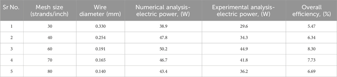
TABLE 5. Experimental electric power generation for different wire mesh.
However, there is some discrepancy between the cyclic analysis predictions and the experimental outcomes. There are several possible clarifications: To begin with, the simulation does not account for the significant heat loss that occurs in experiments. Secondly the acoustic field induced inside the engine is complicated and highly dependent on the individual component’s dimensions. The actual engine’s acoustic fields are altered because of a small discrepancy between the original design and the actual parts. The acoustic field has been partially corrected by the stub section, but more study is required to determine the ideal acoustic field in such a complex system. The mechanical losses in alternator section is bit more which has to be overcome in further works. To minimize power loss due to Joule heating inside the coil, the alternator’s electrical resistance should be small, and its Bl factor should be high to maximize conversion efficiency. To remove the reactive component of the alternator impedance, the generator should run at the resonance frequency of the alternator. But, because the frequency will rise slightly as the engine’s gas heats up during operation, it is not always possible to match the frequency precisely. Nonlinear acoustic behaviour is present in the tested rig, and the pressure amplitude is comparatively larger. However, first time cyclic analysis is used in analysis of thermoacoustic engine and alternator response, which does not account for any nonlinear effects.
5 Conclusion
The looped tube thermoacoustic engine arrangement with the linear alternator has undergone thorough numerically and experimentally analysis. The pressure distribution and the generation, dissipation, and consumption of acoustic and electric power in the thermoacoustic engine is analysed thoroughly using cyclic analysis. The analysis results was used as a reference for building the test equipment, and it was then fine-tuned and adjusted to represent the travelling wave thermoacoustic engine’s actual behavior. The engine is built for a 78 Hz operating frequency to generate the highest power. Analytical and experimental testing of the five various wire mesh sizes 30, 40, 60, 70, and 80 strands/inch produced results with less than 10% variation. The design was made “flexible” using PVC piping in order to manage the total loop length and the position of the linear alternator with reference to the thermoacoustic engine core. In order to generate electricity from acoustic waves, a standard loudspeaker has been utilized as a linear alternator. According to numerical study, the alternator in a thermoacoustic engine extracts about 87.3 W of acoustic power and generates 50.22 W of electric power. Based on the investigation, the ratios of thermal to acoustic efficiency (ηT-A) and acoustic to electric efficiency (ηA-E) and thermal to electric efficiency (ηT-E) are around 16.66%, 57.52 percent, and 9.3%, respectively. The linear alternator is positioned at optimal distance of x = 2.32 m away from engine core which produces the maximum electric power of about 44.9 W with 78 Hz frequency. The thermoacoustic engine produces a maximum of about 44.9 W of electric power for wire mesh 60 strands/inch, with an overall conversion efficiency of about 8.3%.
Data availability statement
The original contributions presented in the study are included in the article/Supplementary material, further inquiries can be directed to the corresponding author.
Author contributions
MG: Conceptualization, Data curation, Formal Analysis, Funding acquisition, Investigation, Methodology, Project administration, Resources, Software, Supervision, Validation, Visualization, Writing–original draft, Writing–review and editing. SSh: Conceptualization, Project administration, Resources, Visualization, Writing–review and editing. MN: Data curation, Formal Analysis, Methodology, Resources, Software, Visualization, Writing–review and editing. TJ: Methodology, Project administration, Resources, Software, Writing–review and editing. RK: Data curation, Validation, Visualization, Writing–review and editing. SSa: Funding acquisition, Investigation, Methodology, Project administration, Writing–review and editing. RC: Funding acquisition, Methodology, Software, Validation, Writing–review and editing. EA: Funding acquisition, Investigation, Methodology, Resources, Validation, Writing–review and editing.
Funding
The author(s) declare financial support was received for the research, authorship, and/or publication of this article. The authors extend their appreciation to King Saud University for funding this work through Researchers Supporting Project number (RSP2024R164), King Saud University, Riyadh, Saudi Arabia.
Conflict of interest
The authors declare that the research was conducted in the absence of any commercial or financial relationships that could be construed as a potential conflict of interest.
Publisher’s note
All claims expressed in this article are solely those of the authors and do not necessarily represent those of their affiliated organizations, or those of the publisher, the editors and the reviewers. Any product that may be evaluated in this article, or claim that may be made by its manufacturer, is not guaranteed or endorsed by the publisher.
References
Abduljalil, A. S., Yu, Z., and Jaworski, A. J. (2011). Selection and experimental evaluation of low-cost porous materials for regenerator applications in thermoacoustic engines. Mater. Des. 32, 217–228. doi:10.1016/j.matdes.2010.06.012
Ahmed, H., and Jaworski, A. J. (2023). Thermoacoustic cascade engine free from resonance length. Energy271 271, 126881. doi:10.1016/j.energy.2023.126881
Ahmed, H., Jaworski, A. J., Mao, X., and Simpson, K. (2018). Design and construction of a two-stage thermoacoustic electricity generator with push-pull linear alternator. Energy144 144, 61–72. doi:10.1016/j.energy.2017.11.148
Backhaus, S., and Swift, G. W. (2000). A thermoacoustic-Stirling heat engine: detailed study. Detail. Study” J. Acoust. Soc. Am. 107 (6), 3148–3166. doi:10.1121/1.429343
Backhaus, S., Tward, E., and Petach, M. (2004). Traveling-wave thermoacoustic electric generator. Appl. Phys. Lett. 85, 1085–1087. doi:10.1063/1.1781739
Chen, B., Fan, J., Ho, K., Yang, M., Tian, S., and Li, H. (2017). Numerical analysis of acoustic field in a 2-stage traveling wave thermoacoustic engine based on DeltaEC. Energy Procedia 105, 4615–4620. doi:10.1016/j.egypro.2017.03.999
Chen, B., Yousif, A. A., Riley, P. H., and Hann, D. B. (2012). Development of thermoacoustic engine operating by waste heat from cooking stove. Engineering 4 (12), 894–902. doi:10.1063/1.4704259
Dhuchakallaya, I., and Saechan, P. (2022). Performance improvement of a thermoacoustic Stirling engine with in-line phase-adjuster. J. Energy Resour. Technol. 144 (5), 052101. doi:10.1115/1.4051757
Fujita, H., Kushiyama, T., Iwabuchi, M., Kanzaka, M., Goto, H., Okada, M., et al. (1983). Development of a large-bored stirling engine in Japan, P. I. Mech. Eng. A-J. Pow. 197 (2), 107–112. doi:10.1243/PIME_PROC_1983_197_012_02
Jia, Z., Wang, R., Hu, J., Zhang, L., Wu, Z., Chen, Y., et al. (2022). Study on the coupling between engine and alternator in a free-piston Stirling generator. Appl. Therm. Eng. 217, 119222. doi:10.1016/j.applthermaleng.2022.119222
Kalid, O. A., Abdoulla-Latiwish, , Mao, X., and Jaworski, A. J. (2017). Thermoacoustic micro-electricity generator for rural dwellings in developing countries driven by waste heat from cooking activities. Energy 134, 1107–1120. doi:10.1016/j.energy.2017.05.029
Kang, H., Cheng, P., Yu, Z., and Zheng, H. (2015). A two-stage traveling-wave thermoacoustic electric generator with loudspeakers as alternators. Appl. Energy 137, 9–17. doi:10.1016/j.apenergy.2014.09.090
Krishna Gaikwad, M., Patil, P. A., Shendage, D., and Bhojwani, V. K. (2018). Design and manufacturing of travelling wave thermo-acoustic engine with varying regenerator length. Int. J. Ambient Energy 41 (8), 945–953. doi:10.1080/01430750.2018.1501736
Krishna Gaikwad, M., Patil, P. A., Thate, V., Jadhav, Y., and Chabukswar, S. (2021). Numerical analysis of travelling wave thermo-acoustic engine considering the wall Prandtl number. Int. J. Ambient Energy 43 (1), 4112–4119. doi:10.1080/01430750.2021.1874523
Krishna Gaikwad, M., Pradeep, A. P., and Virendra, B. (2019). Numerical investigation on the performance of thermo-acoustic engine using a vertical heater. Int. J. Ambient Energy 42 (15), 1769–1775. doi:10.1080/01430750.2019.1614991
Liu, L., Cai, J., and Liu, Y. (2023). Structural optimization of resonance tubes for a looped thermoacoustic engine with multiple heat sources. Case Stud. Therm. Eng. 49, 103344. doi:10.1016/j.csite.2023.103344
Liu, L., Liu, Y., and Duan, F. (2020). Effect of the characteristic time on the system performance of a three-stage looped traveling-wave thermoacoustic engine. Energy Convers. Manag. 224, 113367. doi:10.1016/j.enconman.2020.113367
Mahesh, K. G., and Patil, P. A. (2020). Numerical and experimental investigation on the effect of regenerator mesh size on performance of the traveling wave thermoacoustic-Stirling heat engine. Case Stud. Therm. Eng. 20, 100630. doi:10.1016/j.csite.2020.100630
Martini, W. (1978). “Stirling engine design manual,”. NASA Report 1978 (Washington, D.C., United States: NASA).
Petach, M., Tward, E., and Scott, B. (2004). “Design and testing of a thermal to electric power converter based on thermoacoustic technology,” in 2nd International Energy Conversion Engineering Conference, Providence, Rhode Island, August, 2004. doi:10.2514/6.2004-5518
Saechan, P., and Dhuchakallaya, I. (2020). Design and experimental evaluation of a travelling wave thermoacoustic engine. Energy Rep. 6 (9), 1456–1461. doi:10.1016/j.egyr.2020.11.002
Saechan, P., and Jaworski, A. J. (2018). Thermoacoustic cooler to meet medical storage needs of rural communities in developing countries. Therm. Sci. Eng. Prog. 7, 164–175. doi:10.1016/j.tsep.2018.05.001
Saha, C. R., Riley, P. H., Paul, J., Yu, Z., Jaworski, A. J., and Johnson, C. M. (2012). Halbach array linear alternator for thermo-acoustic engine. Sensors Actuators A Phys. 178, 179–187. doi:10.1016/j.sna.2012.01.042
Shendage, D. J., Kedare, S. B., and Bapat, S. L. (2017). Cyclic analysis and optimization of design parameters for Beta-configuration Stirling engine using rhombic drive. Appl. Therm. Eng. 124, 595–615. doi:10.1016/j.applthermaleng.2017.06.075
Sun, D., Luo, K., Zhang, J., Yan, S. W., and Pan, H. (2021). A novel non-linear one-dimensional unsteady model for thermoacoustic engine and its application on a looped traveling-wave thermoacoustic engine. Appl. Acoust. 181, 108136. doi:10.1016/j.apacoust.2021.108136
Swift, G. W. (1988). Thermoacoustic engines. J. Acoust. Soc. Am. 84 (4), 1145–1180. doi:10.1121/1.396617
Swift, G. W., and Ward, W. C. (1996). Simple harmonic analysis of regenerators. J. thermoacoustic heat Transf. 10 (4), 652–662. doi:10.2514/3.842
Vorotnikov, G. V., Zinovyev, E. A., and Nekrasova, S. O. (2022). Thermodynamic cycle of the traveling wave thermoacoustic engine. Case Stud. Therm. Eng. 36, 102216. doi:10.1016/j.csite.2022.102216
Widyaparaga, A., Hiromatsu, T., Deendarlianto, K. M., and Takata, Y. (2020). Acoustic field alteration in a 100 Hz dual acoustic driver straight tube travelling wave thermoacoustic heat pump for thermoacoustic heat transport control. Int. J. Heat Mass Transf. 151, 119274. doi:10.1016/j.ijheatmasstransfer.2019.119274
Yang, R., Wang, Y., Ye, F., Jin, T., and Tang, K. (2019). Performance of a looped thermoacoustic engine with multiple loads capable of utilizing heat source below 200 °C. Appl. Therm. Eng. 148, 516–523. doi:10.1016/j.applthermaleng.2018.11.069
Yu, Z., Jaworski, A. J., and Scott, B. (2012). Travelling-wave thermoacoustic electricity generator using an ultra-compliant alternator for utilization of low-grade thermal energy. Appl. Energy 99, 135–145. doi:10.1016/j.apenergy.2012.04.046
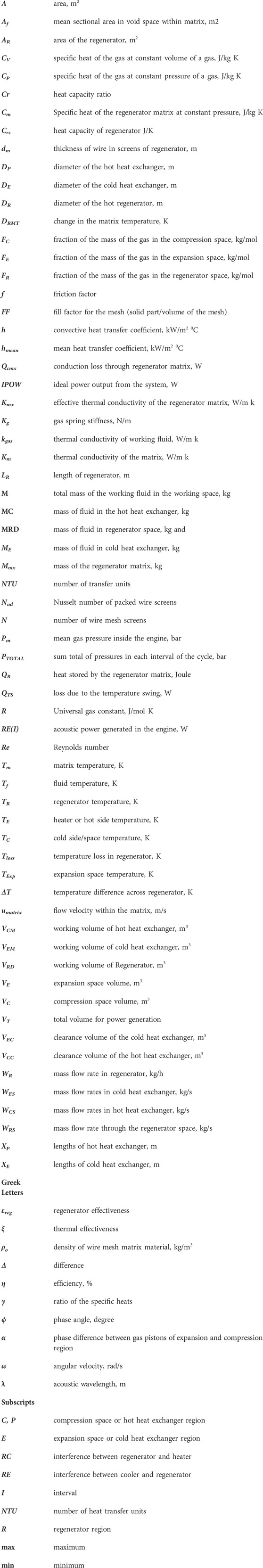
Nomenclature
Keywords: regenerator, travelling wave, power generator, wire mesh, alternator
Citation: Gaikwad MK, Shinde SU, Naidu MJ, Jadhav TA, Kumar R, Salunkhe S, Cep R and Abouel Nasr E (2024) Performance evaluation of looped tube thermoacoustic power generator using cyclic analysis. Front. Mech. Eng 10:1357332. doi: 10.3389/fmech.2024.1357332
Received: 17 December 2023; Accepted: 19 January 2024;
Published: 05 February 2024.
Edited by:
Eswaramoorthy Muthusamy, Shri Mata Vaishno Devi University, IndiaReviewed by:
Peng Yang, Xi’an Jiaotong University, ChinaYuanpeng Yao, Shanghai Jiao Tong University, China
Copyright © 2024 Gaikwad, Shinde, Naidu, Jadhav, Kumar, Salunkhe, Cep and Abouel Nasr. This is an open-access article distributed under the terms of the Creative Commons Attribution License (CC BY). The use, distribution or reproduction in other forums is permitted, provided the original author(s) and the copyright owner(s) are credited and that the original publication in this journal is cited, in accordance with accepted academic practice. No use, distribution or reproduction is permitted which does not comply with these terms.
*Correspondence: Sachin Salunkhe, c2FjaGluc2FsdW5raGVAZ2F6aS5lZHUudHI=