 Ole S. Nesheim
 Sindre W. Eikevåg
 Martin Steinert
 Christer W. Elverum1
- 1Faculty of Engineering, Department of Mechanical and Industrial Engineering, Norwegian University of Science and Technology, Trondheim, Norway
- 2School of Electrical, Electronic and Mechanical Engineering, University of Bristol, Bristol, United Kingdom
Creating specialized components featuring complex structures typically involves extensive time, CAD modelling and manual labor. However, with the right combination of tools and knowledge, complex components can be generated, manufactured, and utilized within hours, rather than weeks or months. By creating a portable manufacturing setup, the designer can produce components on site, significantly enhancing accessibility. An example where time and accessibility are of vital importance is in paralympic cross country skiing where training schedules are tight and snow conditions vary. The aim of this study was to generate and manufacture form-fitted, lightweight knee-supports for a Paralympic sit-ski athlete within 4 days. This was done by 3D printing components generated using Fusion 360s Generative Design (GD), based on inputs from the athlete’s geometry, material testing and force data resulting from the athlete’s weight and movement. A precise fit around the knees was achieved using a high-accuracy 3D scanner and modelling software to create an adjustable prototype to determine knee positions and key angles. Force data from the knees were gathered using a digital twin sit-ski. Based on the collected data, the maximum forces inserted into the GD model were 700N and 500N for the right and left knee, respectively. Material data was obtained through testing ABS samples manufactured under the same conditions as the knee-supports themselves. The Young’s modulus was calculated to
1 Introduction
Additive manufacturing (AM) is widely known to enable the production of complex components (Gao et al., 2015). However, designing such components usually takes time and modelling skills. And in cases where complexity is unavoidable, modelling and strength analysis can take up to weeks or even months. By combining in-situ use of digital twin, knowledge on material data, 3D scanning, generative design (GD) and AM, complex components adapted to a specific use case can be both generated and manufactured in hours as opposed to weeks or even months.
1.1 Form-fitting
Equipment fit is vital when it comes to performance in most sports (Iriberri et al., 2008; Shan, 2008), and when considering paralympic sports the individuality of the equipment is crucial due to the high degree of bodily variations (Eikevåg et al., 2020; Fletcher et al., 2021; Eikevåg et al., 2022; Nesheim et al., 2022). A study on ski boots showed that boots that are wrapped more uniformly around the athlete’s foot, providing uniform pressure transmits energy more efficiently, increasing the peak force during downhill skiing (Colonna et al., 2013; Feeney et al., 2023). Following the same line of reasoning, body-fitted equipment may also provide higher control in paralympic cross country skiing, although there are more contact points in a sit-ski than in traditional skiing, i.e., buttocks, knees and lower legs. Form-fitting equipment to the human user is a technique used in several instances such as wheelchair seats, car racing seats, sports shoes, medicine, orthoses, prosthetics and more. It is highly valuable in terms of ergonomics, damage prevention, reducing pain as well as increasing performance and control (Mao et al., 2021). Form-fitting usually require a lot of manual skilled labor and or big setups with molds covering the part that needs to be form-fitted (Nace et al., 2019). These techniques also provide little control over other interfacing geometry of the part and support structures. By venturing into the digital domain, however, more freedom and possibilities are available in terms of geometric positioning and strength analysis. This may be done by 3D scanning body shapes and working in modelling software (Tasker et al., 2011), followed by 3D printing the finished components, which reduces the need for skilled manual labor.
1.2 Additive manufacturing
The recent advancements in AM have made production of end-use components with this technology possible. AM can produce complex geometries considered impossible in more traditional production methods such as vacuum-assisted resin infusion, injection molding or CNC milling. By being able to produce components with the geometric freedom that AM offers, this technology is highly suitable for creating components based on 3D scanned body parts (Goyanes et al., 2016). There are several successful examples where 3D scanning combined with 3D printing has been used to create form-fitted equipment. For instance, Denise Schindler in collaboration with Autodesk, undertook a project where 3D scanning and 3D printing were used to create an aerodynamic leg prosthetic used for bicycling as reported in a news article from 2016 (Hobson, 2016). According to Schindler, the process of making prosthetics is usually manual and highly time-consuming, and by making the entire process digital, a lot of time can be saved. Other similar work has been done in prosthetics (Sokolowski and Meyer, 2019; Marinopoulos et al., 2023), orthopedics (Negru et al., 2019), implants (Jardini et al., 2014) and orthotics (de Souza et al., 2017; Volonghi et al., 2018).
Metal AM is now considered a well-established production method for manufacturing components with complex geometries with known material characteristics (Agius et al., 2018). Laser sintering of materials such as Ti-6Al-4V yields excellent surface tolerances and lightweight, robust products. AM of metals are also seen in multiple applications, but mainly in the automotive or space industry. This technology could also be applied to prosthetic, e.g., by using titanium with a density of 4.43 g/cm3 and UTS of 850–1,150 MPa (Agius et al., 2018). However, there are several challenges associated with using metal AM. First, the accessibility of metal AM is limited due to a significant equipment cost, material cost and energy consumption. Second, the setup is large and complex. An example of a portable metal AM setup is the one made by Fieldmade (Fieldmade, Norway) which fits a portable setup weighing several tons inside a shipping container that prints Ti-6Al-4V. Third, producing a prototype in metal is quite time-consuming as extensive post processing is commonly required and a small part may take a couple of days in manufacturing time.
Polymer AM might solve all highlighted limitations related to metal AM. Polymer AM technologies, such as Fused Filament Fabrication (FFF), Stereolithography (SLA), Selective Laser Sintering (SLS), and Material Jetting, provide a vast array of material options, ranging from flexible elastomers to high-strength composites. Among polymer AM technologies, FFF is the only portable production method readily scalable for larger components due to the gantry-based system which can fit inside a car within maximum carload weight restrictions, enabling in-field manufacturing. In addition, the strongest published material properties produced through FFF in the weakest axis up to date is 80 MPa with a density of 1.17 g/cm3 (Birkelid et al., 2022; Bjørken et al., 2022). FFF also provides exceptionally low hardware and material costs. In terms of prototyping, time is the most crucial element when creating many iterations. And, as presented in this contribution, FFF technology can easily be modified for more rapid manufacturing by replacing stock components such as the extruder and hot end.
Using low-cost materials such as PLA and ABS, prototypes can be produced for only 20$ per kilogram. Analyzing the anisotropic properties of the low-cost materials (Morettini et al., 2022) provides input for generative design (GD) studies as well as finite element analysis (FEA) simulations, and for this, an accurate Young’s modulus and UTS in the XY and XZ direction is required. While prototyping equipment with weight and load-bearing requirements, material performance studies are crucial to achieve the best prototype functionality. Low-cost materials such as PLA and ABS is weak to continuous cyclic loading (Azadi et al., 2021), but works excellent under static conditions and as prototypes. However for the final iterations for cyclic load-bearing components, FFF technology enables the re-production of the component in high-performance polymers, with no adaption in CAD required. For this high-performance polymer, composite PA6-CF is a strong contender when including fatigue life (Panerai et al., 2023). In summary, FFF is the best candidate when the requirements are manufacturing time, portability, cost, and scalability in the context of rapid prototyping of load-bearing components. FFF can also produce highly complex geometries and designs, such as scanning the human body and load-bearing structures using Generative Design (GD).
1.3 Generative design (GD)
Generative design is an AI based iterative design process, generating outcomes based on specific criteria created by the designer, which can be useful for exploring design possibilities (Krish, 2011; Singh and Gu, 2012). A strong quality of GD is the ability to generate a high number of complex designs in a short period of time, making it a great design tool for creating human centered equipment (Bosquet et al., 2020). Its inherent ability to generate complex shapes also makes it a natural tool for generating components to manufacture with AM (Wang et al., 2021; Ntintakis et al., 2022). This is substantiated by the many examples of GD models manufactured through AM (Fantini et al., 2017; Junk and Rothe, 2022; Autodesk, 2024). GD models are commercially available through various software, however this article will from this point refer to GD as the software package with the same name provided by Autodesk Fusion 360 (Autodesk, San Francisco, California, USA). Other work done on this area consist of GD combined with metal AM for producing automotive parts and support structures (Briard et al., 2020; Zhang et al., 2020). Also, by 3D scanning existing components and setting up a GD model, parts can quickly be replaced (Pollák and Török, 2022). To the authors knowledge, there is a big lack of resarch on applying GD to FFF of polymers as most GD articles focus on software or metal AM. This offers a huge demand for studies combining polymer materials with GD and the applications of it.
A succesful GD model requires several input parameters. In this article, the four main input parameters used are 1. Geometry, 2. Force data, 3. Material data and 4. Manufacturing process. The geometric data defines and constrains the physical shape of the component in its interfacing faces. I.e., measuring instruments are used to identify the key shapes for the component to interract with other components and users, and the positions relative to each other. Force data is a crucial input as it defines the loads the structure needs to withstand. The GD model uses this input to generate a suitable structure. The magnitude of the forces applied to the model will naturally affect the thickness and shape of the optimized support structure. Material data is also needed to the model since most materials acts different under the same load. The thickness and shape of the generated support structure is therefore dependent on the material as well as the applied load. Depending on the manufacturing process, the generative design outcome will be restricted. Some processes, such as turning and milling will for instance, not be able to create internal cavities in the component, whereas additive manufacturing will. The manufacturing process is therefor also a vital input to the GD model as it will define what shapes are prossible to physically create.
1.4 Accessibility
Sports athletes do not necessarily have the time and flexibility that is needed from a designer’s perspective when prototyping new equipment adapted for that individual. Also, when working with winter sports, the snow and weather conditions may change substantially on a daily or hourly basis, rendering a highly complex design challenge. Thus, a fast way of creating testable prototypes with complex geometries is vital when working with this kind of design task. Waiting weeks for parts to be made is highly unpractical. A high-speed 3D printer, able to produce large prototypes on-site in a matter of a few hours is therefore a strong ally to the designer.
By limiting oneself to rely only on relatively small and portable tools (handheld 3D scanners, 3D printers and laptops), the accessibility of the entire setup increases significantly as opposed to being dependent on a laboratory. This is crucial to the entire process presented in this article. A portable manufacturing setup allows the equipment designer to travel to sport events and training camps to create high-end specialized equipment at a low cost for the athlete within hours, ready to be used at the local event. Many athletes do not have the time nor funding to travel across the country (or further) to a stationary laboratory to personalize their equipment although it is highly needed in many sports, especially in paralympic sports.
This study was conducted in relation to a ski event in Norway in March 2023, giving a time constraint of 4 days. The goal of this project was therefore to create stiffness optimized knee-supports form-fitted for an individual paralympic cross country skiing athlete within this time limit. Included in the paper is the design and production method of these components, including all steps necessary to collect the required personal data in the field, generating the design and manufacturing components. Also the modification of a commercially available 3D printer, necessary to achieve a high enough volumetric flow to achieve this goal within the required timeframe is described. This paper is intended to provide a holistic view of how this method can be used in an actual use case, and discuss how it can be generalized first and foremost to the design and production of most completely personalized equipment, but also to other applications. The main innovation of this work is showing how various tools can be combined to create a portable setup that will enable the designer to design and produce such finished components at a reasonable cost within a short time limit.
2 Methods
Each step towards the finished components, illustrated in Figure 1, will be further elaborated in the method and results sections. Given the iterative nature of this method, where each loop is dependent on the feedback from the preceding one, the article is structured by presenting an overview in this section and splitting each loop between the method and the results section.
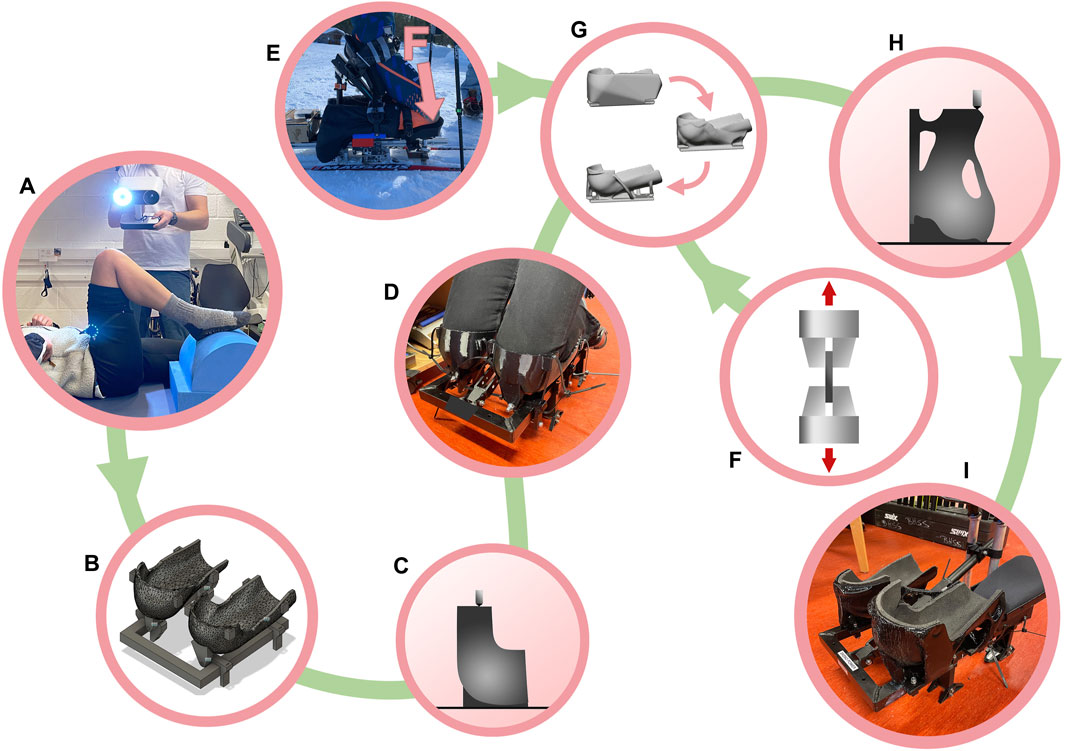
Figure 1. Study overview. (A) 3D scanning of athletes exact knee geometry (B, C) 3D modelling and 3D printing adjustable form-fitted knee-supports (D) Identifying correct knee position and angles (E) Finding maximum knee-forces (F) Material testing (G) Generative design based on inputs from D–F (H) 3D printing generated form-fitted knee-support (I) Finished components mounted onto sit-ski.
In order to create a stiffness optimized structure, a model in Fusion 360s GD software was used. The necessary input parameters for this model were geometry data, force data, and material data.
• Geometry data: The athlete’s knees were scanned using a commercially available 3D scanner in order to obtain the shape of the knees (Figure 1A). Two adjustable knee-supports based on this scan were designed (Figure 1B), manufactured (Figure 1C) and mounted onto the athlete’s sit-ski to find the suitable knee-support angles and position (Figure 1D).
• Force data: A digital twin sit-ski equipped with force sensors mounted at multiple locations, including the knee-supports, was tested by the athlete on a regulated track. Force data was extracted from the knee-supports to obtain the maximum forces (Figure 1E).
• Material data: Dogbone specimens were printed in the same material (ABS) under the same manufacturing conditions as the knee-supports and tested on a load system to determine the Young’s modulus and ultimate tensile strength (UTS) of the printed structure, in both in-plane and out-of-plane direction (Figure 1F).
Using these inputs for the GD model, both knee-supports were generated (Figure 1G), produced using FFF (Figure 1H) and fitted onto the sit-ski (Figure 1I).
2.1 Data collection
As outlined in the method overview, the four required input parameters for creating a GD model were geometry, force data, material data and manufacturing process. These parameters and how they were addressed will be presented in this section. The study was conducted at Beitostølen Helsesportsenter, and all necessary equipment for the project was transported to the site during a training camp and competition with professional Norwegian paralympic athletes. The athlete consented to the study according to NSD-514085, and provided informed written consent prior to the study. The athlete answered six questions designed to qualitatively evaluate the improvement of the knee-supports. This was done both before and after modification. The answers were based on a Likert scale and are presented in the results section.
2.1.1 Geometry data
Figure 2 describes the first steps of the design process. The aim of these steps was to obtain the necessary geometric data as input to the GD model. The athlete’s legs were 3D scanned (Figure 2A) with a 3D scanner (Artec Leo, Artec3D, Luxembourg, Luxembourg) to obtain an accurate shape of the knee in semi-correct position (Seminati et al., 2017). The scan generated a point cloud which was converted into a 3D model of the relevant area and exported as an .stl file using Artec Studio (Artec3D, Luxembourg, Luxembourg). The .stl file was then imported into MeshMixer (Autodesk, San Francisco, California, USA) where the model was converted into a hollow form with a 4 mm offset distance from the knee (Figures 2B, C). The model was then reduced to a model consisting of less than 10,000 faces and exported into Fusion 360, where clamps and attachments were added. An assembly was made consisting of both knee-supports, clamps and the frame interfacing with the knee-supports (Figure 2D). The functional prototype allowed for angular adjustments to be made in-situ, while the athlete was testing the fit. All components for the adjustable prototype were 3D printed and mounted onto the sit-ski. The knee-support angles were adjusted in-situ, i.e., when the athlete sat in the sit-ski (Figure 2E), until suitable angles were identified. The angles, α and β (Figures 2F, G), were measured and written down. This was done for both knees.
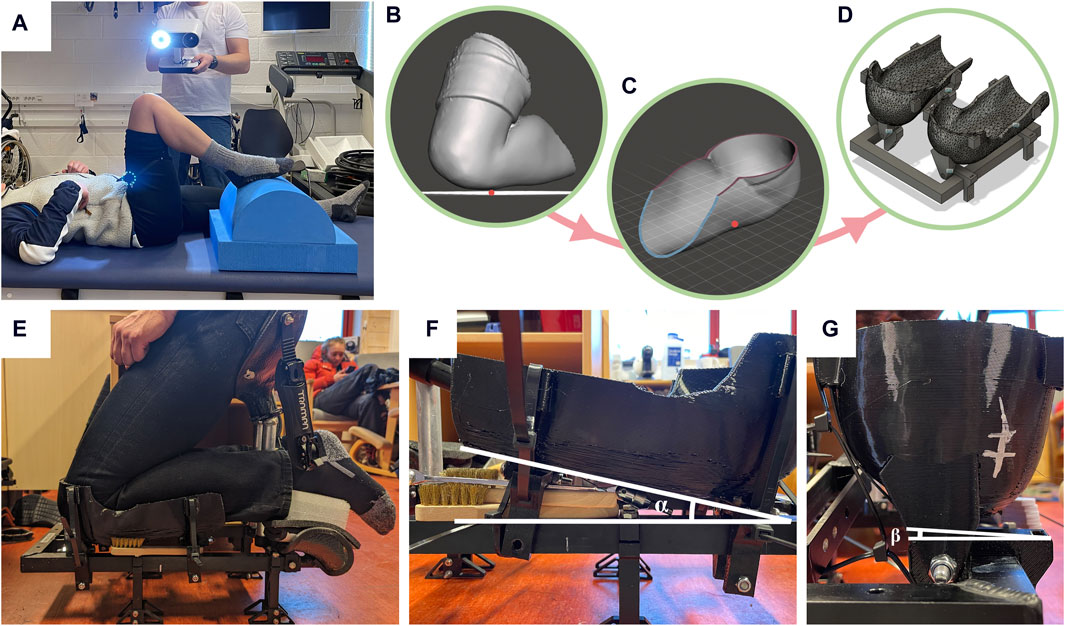
Figure 2. (A) 3D scanning of the athlete’s knees while keeping a knee-seated position (B–D) Designing an adjustable knee-support from the 3D model using MeshMixer and Fusion 360 (E) Test fitting 3D printed knee-supports (F, G) Identifying correct knee-angles.
2.1.2 Force data
As a part of a larger study, an adjustable digital twin sit-ski prototype was developed, equipped with integrated load cells to collect force data from different parts of the sit-ski. In this study, force data was collected by the TAS606 button load cells (SparkFun Electronics, USA) integrated in the knee-supports while the athlete was poling around a track consisting of various features, providing dynamic force data. The TAS606 load cell signal was amplified through a HX711 amplifier (SparkFun Electronics, USA) giving an 80 Hz refresh rate. The signal from both knee-supports were read by and Arduino UNO R3 (Arduino, Turin, Italy) and passed on to a Raspberry Pi 4 Model B (Raspberry Pi Foundation, England). The track was chosen to best represent different parts of a traditional sit-ski track used in competitions (World Para Nordic Skiing, 2021). The athlete performed the track 2 times. A complete description of the digital twin sit-ski and the test track used can be found in the study by Berg et al. (2023).
2.1.3 Material data
The material data was collected separate to the ski event and was not done during the 4 day time limit. As production method affects the material properties [Especially in FFF where material properties tend to be inherently anisotropic (Es-Said et al., 2000; Ahn et al., 2002)], finding multidirectional material properties for the specific material and machine used is vital for a good model. The material used in the study was ABS filament supplied by 3DNet (3DNet, 2023). According to Autodesk Fusion 360, the primary material values used to calculate the next design iteration in the GD process, are the Young’s modulus and the Poisson’s ratio (Autodesk, 2023). In addition, maximum stress is compared to UTS and safety factor. Since strength and stiffness varies based on print parameters and other manufacturing factors, these properties were found for ABS samples printed under the same conditions as the components made in this study. To obtain the Young’s modulus, Eq. 1 was used.
Eq. 1. Calculating Young’s modulus
The forces, F1 and F2, and the strain,
First, specimens were designed with a geometry according to the ISO 527 standard (ISO, 2023). The print parameters are shown in Table 1. SuperSlicer, a forked version of Slic3r based on PrusaSlicer, was used for preparing the print job. The 3D printer used was a commercially available Troodon Core XY (Vivedino, Jinhua, China) modified with two extra SuperVolcano Hotends (E3D, Oxford, United Kingdom) configured in series (stacked) and a Titan Aqua Extruder (E3D, Oxford, United Kingdom).
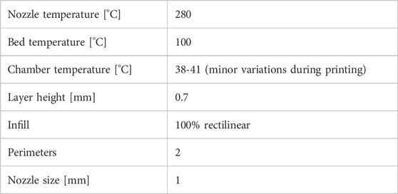
Table 1. Print parameters for dogbone samples.
The specimens were standing (XZ direction) and laying down (XY direction), and eight of each sample was manufactured sequentially (Under “sequential printing” in SuperSlicer, “Complete individual objects” was selected). The samples were then prepared for DIC analysis. All samples were dotted with a white marker according to an online guide (“digitalimagecorrelation.org,” 2023). The samples were tested on a MTS Criterion Electromechanical load system (MTS, Eden Prairie, Minnesota, USA) with model name C42.503: 5 kN. The tensile test speed was adjusted to 1 mm/min. The camera used for taking sample images during loading was an Allied Vision Technologies Stingray F504B ASG camera (Allied Vision Technologies, Stadtroda, Germany) mounted with a C7528-M 75 mm Pentax lens (Ricoh, Tokyo, Japan). Images were collected at 10 fps with a resolution of 2056 × 2,452 pixels. The samples were illuminated with an external light source for better imaging. After collecting force and image data, all images were converted from .tif to .jpeg using Pixillion Image Converter (NCH Software Inc., Denver, Colorado, USA). For each sample, the appropriate images were loaded into GOM Correlate in ZEISS Quality Suite (ZEISS, Oberkochen, Germany). Using “Facet Point Component”, six points were chosen to extract the length change (in the Y-direction) over three distances, i.e., two points per distance. The average length change over the entire component was then calculated from the three distances at two timestamps, i.e., at the beginning and right before yielding. Using metadata showing the time of day from the captured images and the recorded time from the loading system, the amount of strain in the two timestamps were correlated to the load at those times. Both the loads and the strains were noted in an Excel sheet.
The cross-section area of the samples were measured digitally using an Euromex Nexius Zoom microscope with a WD34 2x lens mounted and a VC.3040 UHD-4k camera along with its built in software (Euromex Microscopen B.V., Arnhem, Holland). Images of the cross-sections of all samples were captured at the breaking point and the outline of the samples were marked, producing the area of each cross-section. This was done for all samples and written down in the aforementioned Excel sheet. Eq. 1 was then used to calculate the Young’s modulus for each sample. The average and standard deviation was then calculated for all eight samples of the same type, i.e., XZ-direction and XY-direction. The ultimate tensile strength (UTS) was found by identifying the peak load point on each sample from the output of the loading system and dividing it by the cross-section area. This was done for all test samples, giving the average and standard deviation.
2.2 Design and manufacturing process
The angles, α and β (found in Figure 2; Section 2.1.1) were replicated in the CAD assembly, positioning the knee-supports correctly relative to the sit-ski according to the physical requirements made by the athlete. A new model of the knee-support was then designed in MeshMixer with a 7 mm offset to allow space for padding to be installed. In addition, during fitting, the athlete made a remark that the supports pressed uncomfortably in a certain point on the front of the knee. The appropriate point was marked out on the physical prototype and expanded accordingly in the digital prototype in MeshMixer. A new model of the knee-support was exported from MeshMixer as an .stl file and imported into Fusion 360 as a mesh into the CAD assembly to replicate the correct angle relative to the frame. The mesh was converted into a solid using the organic method to reduce the number of faces on the component. This was a necessary step since the two other methods (i.e., faceted and prismatic) resulted in a component with way more faces than in the former method. When adding forces into the generative design model, each face experiencing force is manually selected to achieve a realistic scenario. Thus, dealing with few faces is favored over dealing with too many, making the selection and computation processes faster. The old supports were removed from the model, and a clamp was designed interfacing with the frame of the sit-ski, to angle the new supports correctly relative to the clamp. Both the clamp and the support were loaded into the generative design environment in Fusion 360 where forces and constraints were applied to the model (Figure 3). Since the GD algorithm adds needed material to handle the forces applied to the model, the second model from MeshMixer was designed with a thinner shell than the first prototype.
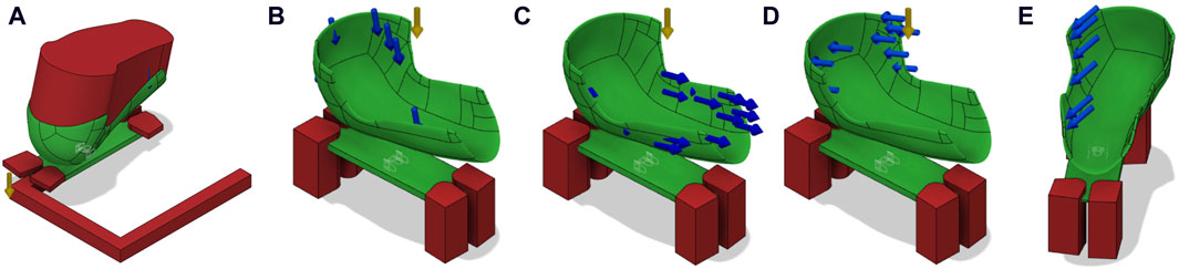
Figure 3. (A) No-build volumes defined inside the generative design environment (i.e., the red volumes). (B–E) Relevant load scenarios defined.
No-build volumes of the model were then defined (Figure 3A). Boundary conditions were defined as follows. Fixed constraints were added to the surfaces interfacing with the sit-ski frame below the bottom plate. For each knee-support, four force scenarios were defined: Downwards force (Figure 3B), forward force (Figure 3C), backwards force (Figure 3D) and leaning force from the athlete located on the edge (Figure 3E). The force input data was chosen based on the results from the digital twin data and can be found in Table 2.
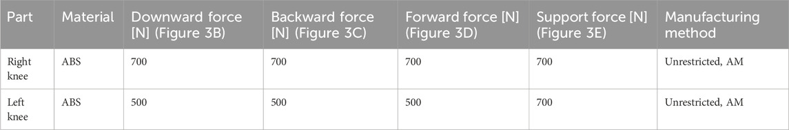
Table 2. Generative design input data based on the results in section 4.1.
Under Objectives in the Design Criteria tab, Maximize Stiffness was selected, where Safety Factor was set to 1.00 and Mass Target was 0.10 kg. Maximize stiffness with 100 g as target weight was chosen over Minimize Mass because we deemed it more important to increase the stiffness of the sports equipment rather than extensively reducing its weight. Manufacturing method was adjusted to Unrestricted and AM. Unrestricted was chosen in addition to AM because the authors wanted to investigate other design possibilities than the ones optimized for additive manufacturing in order not to lose potential design options that only required small modifications to be done before production. Both knee-supports were generated resulting in seven models for each knee to choose from. Appropriate models were chosen based on a visual inspection of print direction and potential overhang issues, and both knee-supports were 3D printed. Important print parameters were nozzle temperature: 280°C, bed temperature: 100°C, chamber temperature: 38°C–41°C (small variations during printing), layer height: 0.7 mm, infill: 20% gyroid, perimeters: 2. The new knee-supports were then mounted onto the sit-ski and tested by the athlete. A timeline showing the entire design and building process can be seen in Figure 4.
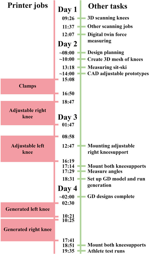
Figure 4. Timeline of design and building process. Left side illustrate printer jobs and right side shows other relevant tasks.
As seen in the timeline, the printer ran almost continuously. The components for the adjustable knee-supports (clamps and both knee supports) were printed as fast as possible after knee geometry was obtained by scanning and force data was obtained through the digital twin on day 1 and day 2. Right after the components were produced, the components were assembled and the angles were found, giving us the last necessary parameters for the GD model. After the GD designs were complete, the two generated knee support designs were printed. In addition to the print jobs shown in the timeline, other jobs were also done, but were not included in the figure as they were not relevant for this exact case.
3 Speed enhancing a commercially available 3D printer
As portability, speed and price was vital for the project, a polymer FFF 3D printer was the chosen manufacturing tool. The printer kinematics were controlled through CoreXY, giving a reduced weight compared to a Cartesian setup, enabling higher tool head acceleration. The printer was also chosen due to its large print volume able to produce components of substantial size. Due to the time constraint we wanted to reduce the manufacturing time. For this reason, a custom-made extruder was developed to double the maximum volumetric flow. This was achieved by extending the melt-zone of the hot-end (Figure 5).
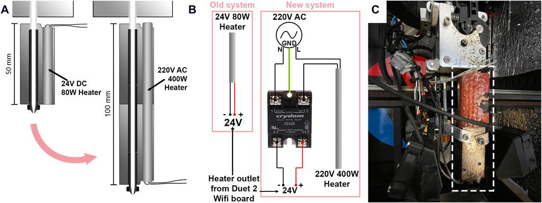
Figure 5. (A) Illustration of how the melt zone was extended by adding another SuperVolcano and changing the heater cartridge (B) Wiring diagram of old and new heater cartridge (C) Image of the modified 3D printer. Extended melt zone is indicated by a white rectangle.
By doubling the length of the melt zone, the maximum volumetric flow (mm3/s) limit of the hot end was roughly doubled. The maximum material flow through a stock SuperVolcano is rated for 110 mm3/s (E3D, 2019) for PLA, meaning that the modified hot end should be able to print at a maximum volumetric flow of 220 mm3/s. The print speed could then be increased while maintaining the layer height, ultimately reducing the print time of a given component. Since the 24V DC, 80W heater cartridge was replaced by a 220V AC, 400W heater, the wiring was redone (Figure 5B). One end of the heater cartridge was connected directly to the 220V AC power supply of the printer and the second to the AC side of a Crydom solid state relay (SSR) (Crydom Inc., San Diego, California, USA). The DC side of the SSR was then connected to the existing 24V heater control output on the Duet 2 Wifi board controlling the printer. PID tuning of the new heater was then done according to an online guide (Duet WiFi/Eth–PID tuning hotend, 2017). The printer was calibrated for height, temperature, and extrusion speed.
4 Results
All the results, i.e., partial results from each step of the design and manufacturing process, and the final knee-supports will be presented in this section.
4.1 Force data
Graphs showing the collected force data from the digital twin knee-supports can be seen in Figure 6. Each graph represents one stroke and is normalized in the x-axis. The four graphs show four distinct sections of the track, chosen to observe the stroke variations in the various features of a standard paralympic cross country skiing track. The middle line in all graphs represents the mean force value of all rounds, and the shaded area represents the standard deviation. The force variations from lowest to highest is most profound in Figure 6D. In this graph, the mean right knee force oscillates from ∼100N to ∼400N. This value can be used for determining fatigue life of the components. Based on the available data, the maximum values for the right knee were set to 700N and the left knee to 500N. The 200N force difference was decided due to the discrepancy between the knees observed in the downhill double poling section of the track (Figure 6A).
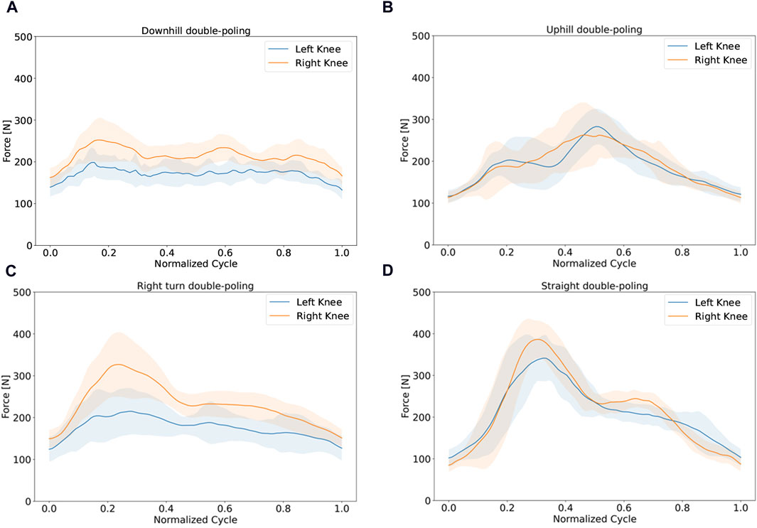
Figure 6. Force data from load cells on digital twin in different sections of the test track. All figures contain mean (solid line) and standard deviation (shaded area) (A) Downhill double poling (B) Uphill double-poling (C) Right turn double poling (D) Straight double poling.
4.2 Material data
The load over time data from the tensile test plotted in Figure 7. The green and pink plots represent the samples printed in XY direction (flat) and XZ direction (standing) respectively. After using the method described in Section 2.1.3, the mean and standard deviation of the Young’s modulus were calculated to
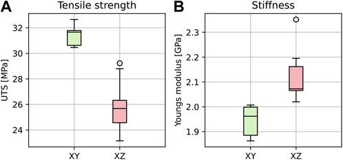
Figure 7. (A) Ultimate tensile strength (UTS) and (B) Young’s modulus results shown as box plots. The green and pink plots show the results from samples printed in the XY and XZ direction respectively. The whiskers show the minimum and maximum, the boxes cover the interquartile interval including the median line, and outliers are indicated as circles.
4.3 Generative design model
Figure 8 illustrates the iterative GD process. The GD model converged after 37 iterations, resulting in a model with a mass of 0.584kg, maximum von mises stress of 20 MPa and maximum displacement of 4.4995 mm given the relevant load scenario.
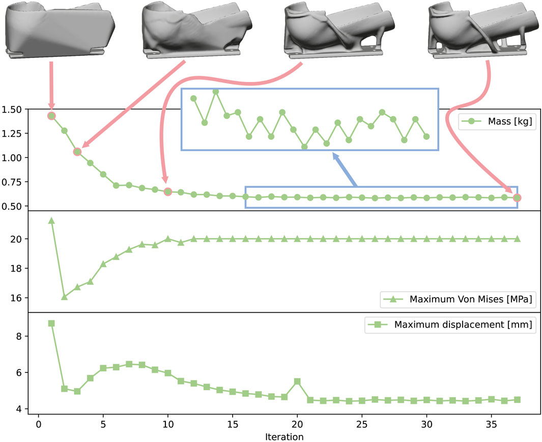
Figure 8. GD iterations in Fusion 360. Images show the knee-supports in iterations 1, 3, 10 and 37. The presented properties are (from the top down) mass [kg], maximum von mises stress [MPa] and maximum displacement [mm]. The blue square shows fluctuations in mass between each iteration in the GD process.
4.4 Process results
Table 3 presents all the prototypes made using the 3D printer. The table provides the printing time and the resulting component weight for each print job. Generated right knee was printed later with further optimized settings and the print time was reduced to 4 h and 40 min, rendering average material flow to 100.28 g/h. Calculating with an ABS material density of 1.03 g/cm3, gives an average volumetric flow of 27.04 mm3/s.
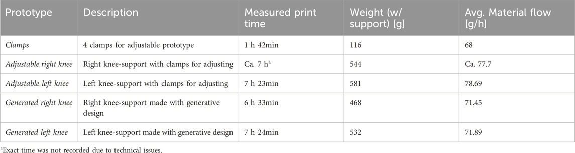
Table 3. All prototypes made using the 3D printer along with printing time and component weight.
CAD model of the left knee-support, finished printed knee-support, the knee-support mounted on the sit-ski and a schematic showing print orientation can be seen in Figure 9. The component was printed as shown in the figure, requiring a support structure at the very bottom. Further support structures on the top of the figure were however removed as it saved more time. This lead to some bridging issues. Some stringing and drooping can also be observed in Figure 9B. The drooping did not bring any issues and the stringing was removed using a heat gun. During mounting, a section of the bottom-clamp of the knee-support intersected with a part of the sit-ski. This section was removed using a hacksaw (Figure 9C).
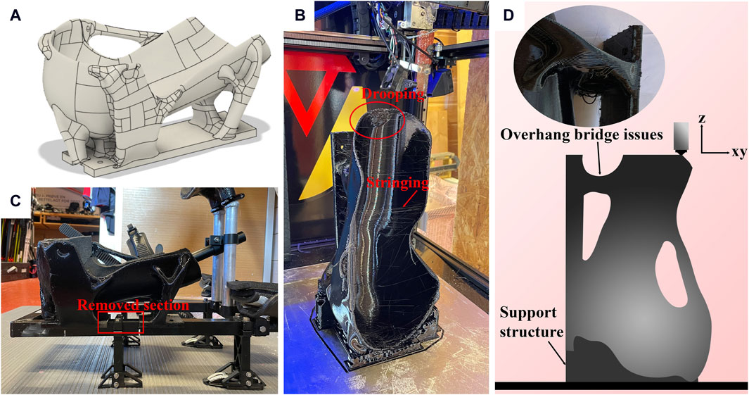
Figure 9. (A) CAD model of the generated left knee-support (B) 3D printed knee-support (C) Knee-support mounted onto the sit-ski (D) Schematic showing print orientation, support structures and overhang area leading to bridging issues.
4.5 Component results
Figure 10 displays pictures of the knee-supports mounted onto the sit-ski from various angles with and without the athlete. Paddings were first inserted in the supports. These were, however, quickly removed after the athlete commented that it removed “the molded feeling”. The athlete instead used an extra layer of fabric on the thighs and knees as seen in the top middle image. The athlete tested the sit-ski mounted with new knee-supports in a slope and provided positive feedback, commenting that they had a much better fit than the existing equipment and provided much higher control over the sit-ski.
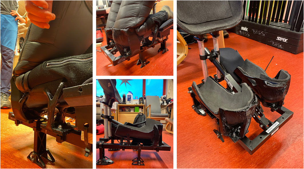
Figure 10. Picture of both knee-supports mounted onto the sit-ski with and without the athlete.
4.6 Qualitative results
The questions presented in Table 4 were originally presented in Norwegian but are translated to English for presentability.
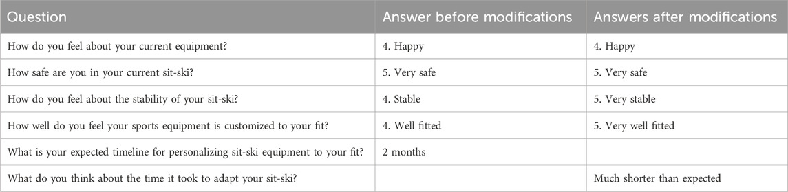
Table 4. All questions in the survey answered using the Likert scale.
5 Discussion and future research
Both sports and other equipment may become more personalized to the user, as presented in this article. When equipment customization is easier and faster, it may become more easily accessible. By, e.g., standardizing the weight and the forces the structure needs to withstand, the only individual differences are the human geometries, making this process suitable for mass customization.
According to the athlete feedback, the change was a slight increase in stability and fit (i.e., from four to five on the Likert scale). It is however necessary to underline that this was a purely qualitative investigation and as the athlete did not know how the results would be while testing the old design, the improvement of the “fit sensation” may have been higher than what is apparent from the survey. And, according to the athlete’s comments, the new design was a substantial improvement over the previous equipment. More cases are necessary to investigate if the effect is positive. This should be combined with test runs measuring heart rate, speed and other physiological data comparing old and new equipment to investigate whether there is a performance increase.
As seen in the timeline in Figure 4, the printer ran almost continuously. Given the tight schedule, the jobs would never have finished before the 4 day time limit without the necessary modifications done to the 3D printer to increase the volumetric flow, ultimately reducing manufacturing time. There are several bottlenecks that may arise when trying to reduce manufacturing time. Stepper motor speed and inertia, volumetric flow, material cooling, tool head weight and other hardware limits all play a part to this goal. Many commercially available printers (and modified ones) can print at very high speeds, however this is often done with small nozzle sizes and low layer heights to increase quality and to show off impressive tool head velocities. So in order to reduce manufacturing time of bigger components the volumetric flow needs to increase accordingly. We achieved this by adding more mass to the tool head. Following this development, stronger stepper motors enabling higher accelerations of a heavier tool head will probably be necessary to reduce the manufacturing time of larger components further. By being smarter with material choices and conducting thermal analysis of the hotend (Colon et al., 2023) a lighter toolhead with the same volumetric flow capabilities can also be made. This is a big area for future research. Following the development of 3D printer technology, printers with these modifications will almost certainly arrive in the future, making design cases like this more possible and easier to conduct. Due to the high volumetric flow demands, the nozzle diameter was 1 mm. The nozzle diameter and following surface roughness was never experienced as an issue in the study, perhaps due to the fabrics building between the athlete and the components. Also, a smaller nozzle diameter would result in longer manufacturing time. Visa versa, a larger nozzle size may help increase the volumetric flow, reducing the manufacturing time further, so this should be investigated in the future. Surface quality will however always be a trade-off to nozzle diameter in finer detailed regions. Other print parameters and path optimization should be investigated in the future with the aim of reducing manufacturing time. Regarding the scanner choice, we believe the same goal can be achieved with other scanners with similar accuracy and portability on the market with a lower cost.
The total manufacturing time was quite low, i.e., it took 4 h and 40 min making one knee-support, after the settings were optimized. Also, since there was no need for any handcrafting when making the form-fitted knee-supports, other useful work could be done during the manufacturing process. A new iteration can also be made quite fast if necessary, without the need of, e.g., skilled workers laying carbon fiber sheets. In addition, working with a digital copy of the athlete’s body shape reduces the time needed from the athletes to create molds from their body parts. The 3D scanning session was quite quick and can then be used for all future prototypes. On the other hand, the athlete’s body will change over time, so when the component does not fit anymore it will be necessary to scan the relevant body parts again in the future. This is however the case for all rigid form-fitted components, and in this case, the digital model can easily be modified with the new scan and then be re-printed.
There are several improvements that can still be done to the presented approach. One can go through several iterations using low cost materials like ABS, before a final lighter version is printed in a material with higher strength, such as Nylon or PEEK (Das et al., 2020). A new design will then need to be generated with the superior material as input to the GD algorithm. ABS is highly recyclable (Mohammed et al., 2017), which means that new filament can be produced from the used prototypes. If recycled ABS is used in future studies, then more knowledge on degradation effects of the material is also needed. Substantial knowledge on strength and fatigue properties of the stronger material are needed in order to predict how long the component will last before failing. Naturally, considerable knowledge on the processing parameters necessary to 3D print with these high strength materials is also vital for successfully creating a component with sufficient strength in all directions. If one uses a highly recyclable material as the end-product, then recycling it to create new 3D printing filament can also be done to reduce waste. The material can then be used, e.g., to create a new component based on a new 3D scan of the athlete done because of body changes that resulted in a bad fit. By having recyclability in mind, the entire process can be made circular, minimizing waste from sports equipment.
The method presented in this paper has only considered the knee-supports. It can however also be applied to other parts of the sit-ski that interfaces with the athlete, such as the lower legs and the buttocks. Other sports engineering examples that could benefit from this method include bicycling, downhill skiing, rowing, bobsleigh racing and generally most sports where the human contact with the equipment is vital for performance, control, and comfort. Accessibility can also be improved in these examples by letting the designer come to the athlete for sporting events and training camps. On a more general note, this method can be applied to many other applications as well, outside of sports engineering, such as creating support structures for other organic shapes that are more difficult to tackle with CAD and traditional manufacturing. The method can be useful when dealing with complex structural engineering issues such as machines and structures where there is no CAD file to represent the reality. Complex structures are introduced in every step of the process. i.e., in both 3D scanning of the knees and in generating the load bearing structure. Since additive manufacturing is inherently designed for manufacturing complex structures, this method makes an excellent use case of 3D printing.
The supports were printed with 20% infill, which would not guarantee the strength according to Fusion 360 GD results, as it generates solid structures. The decision of printing with 20% infill were however made based on empirical data suggesting that the resulting structure were highly over-dimensioned, in addition to the authors being under a time constraint. As Fusion 360s generative design software is designed to provide the optimal structure that will handle the force input with accordance to the safety factor and weight target provided during the workflow, the strength of the component was neither verified through a physical nor digital strength analysis, but tested in practice by the athlete in a slope. Such a verification is out of the scope of this article but is needed in future work in order to create optimal lightweight stiff structures for this purpose. It is then important to verify both strength, stiffness, and fatigue properties.
The SuperVolcano heater is rated for 110 mm3/s, which means the modification done to the printer used in this study should be rated for roughly 220 mm3/s. As we achieved an average of 27.04 mm3/s this may seem quite low. This may however be explained by material choice (i.e., 100 mm3/s was rated for PLA), and the slicer’s toolpaths. Depending on how SuperSlicer plans the print path, the print time can be reduced. Examples of time thieves during the print process are overhangs that needs to be printed slowly for the material to cool down, long travel paths without extruding filament, many small print operations leading to extensive use of stops and lifting of the print head instead of continuous movement and flow. Also running the printer at 100% speed all the time in a closed chamber makes thin walls collapse due to the heat, so naturally some sections of the component was printed at lower speeds. This only shows that in order to achieve faster component production, several factors need to be investigated, not only volumetric flow. More research is needed in order to reduce the final manufacturing time.
From a design perspective, several changes were made during the development process. E.g., when the athlete criticized the fit of one of the knee-supports, it was fixed in the next iteration. In addition, space for padding was added to the knee-supports in the second iteration, however the athlete wanted it removed and used extra fabric on the knees instead, as the padding removed the “molded feeling” of the knee-supports. Both these modifications illustrate the importance of carrying on changes to the next iteration and keeping an open mind for feedback during a design process. Other modifications that could have been done is lowering the knee-supports towards the ground with the aim of creating a more aggressive and stable position. This is however subject to how position changes may increase performance. It would also require another design iteration created using GD. All these changes demonstrated the importance of keeping a holistic view on complex design problem.
The force measuring system could also be improved and more customized for the purpose used in this study. The data extracted from the digital twin sit-ski only represented the downward force of the knees. However, the real force picture is more complex and to get a more comprehensive understanding of what forces the athlete protrudes, all three dimensions should be covered by load cells.
6 Conclusion
This research has shown that by combining the correct tools it is possible to create high-end user specialized equipment with a high degree of complexity on-site within a short period of time. The entire process resulting in two finished ready to use form-fitted stiffness optimized knee-supports were produced in less than 4 days where the final 468 g version of one support was manufactured in 4 h and 40 min. The new form-fitted components were a clear improvement over the previous equipment. These goals were achieved by combining digital twin data, 3D scanning, material testing, generative design, and high-speed additive manufacturing. The method used in this research can clearly be adapted to other design problems with high geometry complexity. The authors believe that this paper serves as a good example of how 3D printer technology can be fully utilized in the future as faster printers and more portable and accessible technology emerges.
Data availability statement
Datasets are available on request: The raw data supporting the conclusions of this article will be made available by the authors, without undue reservation.
Ethics statement
The studies involving humans were approved by the Norwegian Centre for Research Data. The studies were conducted in accordance with the local legislation and institutional requirements. The participants provided their written informed consent to participate in this study. Written informed consent was obtained from the individual(s) for the publication of any potentially identifiable images or data included in this article.
Author contributions
ON: Conceptualization, Data curation, Formal Analysis, Investigation, Methodology, Software, Validation, Visualization, Writing–original draft, Writing–review and editing. SE: Conceptualization, Formal analysis, Investigation, Software, Writing–review and editing. MS: Project administration, Supervision, Writing–review and editing. CE: Project administration, Resources, Supervision, Writing–review and editing.
Funding
The author(s) declare that no financial support was received for the research, authorship, and/or publication of this article.
Acknowledgments
Thank you to Oslo Met for providing the 3D scanner along with appropriate software and knowledge used in this study. Also thank you to the master students of TrollLabs 22/23 for designing and building a digital twin sit-ski used for this and other case studies. Thank you to Beitostølen helsesportsenter for assisting with the experiment and letting us use their infrastructure. Thanks to the Austrian bachelor student joining the authors during building for useful insights. And thank you to the athlete freely participating in this study.
Conflict of interest
The authors declare that the research was conducted in the absence of any commercial or financial relationships that could be construed as a potential conflict of interest.
Publisher’s note
All claims expressed in this article are solely those of the authors and do not necessarily represent those of their affiliated organizations, or those of the publisher, the editors and the reviewers. Any product that may be evaluated in this article, or claim that may be made by its manufacturer, is not guaranteed or endorsed by the publisher.
References
Agius, D., Kourousis, K. I., and Wallbrink, C. (2018). A review of the as-built SLM Ti-6Al-4V mechanical properties towards achieving fatigue resistant designs. Metals 8, 75. doi:10.3390/met8010075
Ahn, S., Montero, M., Odell, D., Roundy, S., and Wright, P. K. (2002). Anisotropic material properties of fused deposition modeling ABS. Rapid Prototyp. J. 8, 248–257. doi:10.1108/13552540210441166
Autodesk (2023). Fusion 360. Autodesk. Available at: https://help.autodesk.com/view/fusion360/ENU/?guid=GD-STUDY-MATERIALS (Accessed January 9, 23).
Autodesk (2024). General motors [WWW document]. Autodesk. Available at: https://www.autodesk.com/customer-stories/general-motors-generative-design (Accessed February 22, 24).
Azadi, M., Dadashi, A., Dezianian, S., Kianifar, M., Torkaman, S., and Chiyani, M. (2021). High-cycle bending fatigue properties of additive-manufactured ABS and PLA polymers fabricated by fused deposition modeling 3D-printing. Forces Mech. 3, 100016. doi:10.1016/j.finmec.2021.100016
Berg, M. F., Døsvik, H., Skjølsvik, K. Ø., Pedersen, T. S., Aasan, V., Steinert, M., et al. (2023). Wireless sensor system for real-time performance monitoring in sports. Front. Sports Act. Living 5, 1305117. doi:10.3389/fspor.2023.1305117
Birkelid, A. H., Eikevåg, S. W., Elverum, C. W., and Steinert, M. (2022). High-performance polymer 3D printing–Open-source liquid cooled scalable printer design. HardwareX 11, e00265. doi:10.1016/j.ohx.2022.e00265
Bjørken, O. U., Andresen, B., Eikevåg, S. W., Steinert, M., and Elverum, C. W. (2022). Thermal layer design in fused filament fabrication. Appl. Sci. 12, 7056. doi:10.3390/app12147056
Bosquet, A., Mueller, C., and Hosoi, A. E. (2020). Body scan processing, generative design, and multiobjective evaluation of sports bras. Appl. Sci. 10, 6126. doi:10.3390/app10176126
Briard, T., Segonds, F., and Zamariola, N. (2020). G-DfAM: a methodological proposal of generative design for additive manufacturing in the automotive industry. Int. J. Interact. Des. Manuf. 14, 875–886. doi:10.1007/s12008-020-00669-6
Colon, A. R., Kazmer, D. O., Peterson, A. M., and Seppala, J. E. (2023). Steady melting in material extrusion additive manufacturing. Rapid Prototyp. J. 30, 85–94. doi:10.1108/RPJ-06-2023-0185
Colonna, M., Nicotra, M., and Moncalero, M. (2013). Materials, designs and standards used in ski-boots for alpine skiing. Sports 1, 78–113. doi:10.3390/sports1040078
Das, A., Chatham, C. A., Fallon, J. J., Zawaski, C. E., Gilmer, E. L., Williams, C. B., et al. (2020). Current understanding and challenges in high temperature additive manufacturing of engineering thermoplastic polymers. Addit. Manuf. 34, 101218. doi:10.1016/j.addma.2020.101218
de Souza, M. A., Schmitz, C., Pinhel, M. M., Palma Setti, J. A., and Nohama, P. (2017). “Proposal of custom made wrist orthoses based on 3D modelling and 3D printing,” in 2017 39th annual international conference of the IEEE engineering in medicine and biology society (EMBC). Presented at the 2017 39th annual international conference of the IEEE engineering in medicine and biology society (USA: EMBC), 3789–3792. doi:10.1109/EMBC.2017.8037682
3DNet (2023). 3DNet [WWW document]. 3DNet. Available at: https://3dnet.no/products/3dnet-abs-xl-2-85-3-00-kg.
Duet WiFi/Eth – PID tuning hotend (2017). Duet WiFi/Eth – PID tuning hotend. Available at: https://betrue3d.dk/duet-wifieth-pid-tuning-hotend/.
Eikevåg, S. W., Erichsen, J. F., and Steinert, M. (2022). Sports equipment design impact on athlete performance – the PR1 Paralympic women’s indoor rowing world record. Eng. Sport 2.
Eikevåg, S. W., Kvam, A., Bjølseth, M. K., Erichsen, J. F., and Steinert, M. (2020). DESIGNING AN EXPERIMENT FOR EVALUATING SEATING POSITIONS IN PARALYMPIC ROWING. Proc. Des. Soc. Des. Conf. 1, 2485–2494. doi:10.1017/dsd.2020.101
Es-Said, O. S., Foyos, J., Noorani, R., Mendelson, M., Marloth, R., and Pregger, B. A. (2000). Effect of layer orientation on mechanical properties of rapid prototyped samples. Mater. Manuf. Process. 15, 107–122. doi:10.1080/10426910008912976
Fantini, M., De Crescenzio, F., Brognara, L., and Baldini, N. (2017). “Design and Rapid Manufacturing of a customized foot orthosis: a first methodological study,” in Advances on mechanics, design engineering and manufacturing: proceedings of the international joint conference on mechanics, design engineering and advanced manufacturing (JCM 2016), 14-16 september, 2016, catania, Italy, lecture notes in mechanical engineering. Editors B. Eynard, V. Nigrelli, S. M. Oliveri, G. Peris-Fajarnes, and S. Rizzuti (Cham: Springer International Publishing), 457–467. doi:10.1007/978-3-319-45781-9_46
Feeney, D., Harrison, K., Luftglass, A., and Honert, E. (2023). A wrapping fit of ski boots improves performance and fit in skiers. Footwear Sci. 15, S97–S98. doi:10.1080/19424280.2023.2199312
Fletcher, J. R., Gallinger, T., and Prince, F. (2021). How can biomechanics improve physical preparation and performance in paralympic athletes? A narrative review. Sports 9, 89. doi:10.3390/sports9070089
Gao, W., Zhang, Y., Ramanujan, D., Ramani, K., Chen, Y., Williams, C. B., et al. (2015). The status, challenges, and future of additive manufacturing in engineering. Computer-Aided Des. 69, 65–89. doi:10.1016/j.cad.2015.04.001
Goyanes, A., Det-Amornrat, U., Wang, J., Basit, A. W., and Gaisford, S. (2016). 3D scanning and 3D printing as innovative technologies for fabricating personalized topical drug delivery systems. J. Control. Release 234, 41–48. doi:10.1016/j.jconrel.2016.05.034
Hobson, B. (2016). Paralympic cyclist Denise Schindler to use 3D-printed prosthesis. Dezeen. Available at: https://www.dezeen.com/2016/05/12/video-interview-denise-schindler-worlds-first-paralympic-cyclist-3d-printed-prosthesis-autodesk-movie/
Iriberri, J., Muriel, X., and Larrazabal, I. (2008). The bike fit of the road professional cyclist related to anthropometric measurements and the torque of de crank 6.
ISO (2023). ISO. Available at: https://www.iso.org/standard/85809.html.
Jardini, A. L., Larosa, M. A., de Carvalho Zavaglia, C. A., Bernardes, L. F., Lambert, C. S., Kharmandayan, P., et al. (2014). Customised titanium implant fabricated in additive manufacturing for craniomaxillofacial surgery. Virtual Phys. Prototyp. 9, 115–125. doi:10.1080/17452759.2014.900857
Junk, S., and Rothe, N. (2022). Lightweight design of automotive components using generative design with fiber-reinforced additive manufacturing. Procedia CIRP, 32nd CIRP Des. Conf. (CIRP Des. 2022) - Des. a changing world 109, 119–124. doi:10.1016/j.procir.2022.05.224
Krish, S. (2011). A practical generative design method. Computer-Aided Des. 43, 88–100. doi:10.1016/j.cad.2010.09.009
Mao, A., Zhang, H., Xie, Z., Yu, M., Liu, Y.-J., and He, Y. (2021). Automatic sitting pose generation for ergonomic ratings of chairs. IEEE Trans. Vis. Comput. Graph. 27, 1890–1903. doi:10.1109/TVCG.2019.2938746
Marinopoulos, T., Li, S., and Silberschmidt, V. V. (2023). Structural integrity of 3D-printed prosthetic sockets: experimental study for paediatric applications. J. Mater. Res. Technol. 24, 2734–2742. doi:10.1016/j.jmrt.2023.03.192
Mohammed, M. I., Das, A., Gomez-Kervin, E., Wilson, D., and Gibson, I. (2017). EcoPrinting: investigating the use of 100% recycled acrylonitrile butadiene styrene (ABS) for additive manufacturing. Univ. Tex. A. T. Austin.
Morettini, G., Palmieri, M., Capponi, L., and Landi, L. (2022). Comprehensive characterization of mechanical and physical properties of PLA structures printed by FFF-3D-printing process in different directions. Prog. Addit. Manuf. 7, 1111–1122. doi:10.1007/s40964-022-00285-8
Nace, S., Tiernan, J., and Ní Annaidh, A. (2019). Manufacturing custom-contoured wheelchair seating: a state-of-the-art review. Prosthet. Orthot. Int. 43, 382–395. doi:10.1177/0309364619836028
Negru, N., Leba, M., Rosca, S., Marica, L., and Ionica, A. (2019). A new approach on 3D scanning-printing technologies with medical applications. IOP Conf. Ser. Mater. Sci. Eng. 572, 012049. doi:10.1088/1757-899X/572/1/012049
Nesheim, O. S., Bentengen, D. H., Eikevåg, S. W., and Steinert, M. (2022). Human geometries as key starting point in sports performance - designing equipment for individual performance in paralympic sit-ski. Proc. Des. Soc. 2, 2147–2154. doi:10.1017/pds.2022.217
Ntintakis, I., Stavroulakis, G. E., Sfakianakis, G., and Fiotodimitrakis, N. (2022). “Utilizing generative design for additive manufacturing,” in Recent advances in manufacturing processes and systems, lecture notes in mechanical engineering. Editors H. K. Dave, U. S. Dixit, and D. Nedelcu (Singapore: Springer Nature), 977–989. doi:10.1007/978-981-16-7787-8_78
Panerai, A., Canegrati, A., Martulli, L. M., Kostovic, M., Rollo, G., Sorrentino, A., et al. (2023). Fatigue behaviour of additively manufactured short fibre reinforced polyamide. Int. J. Fatigue 174, 107711. doi:10.1016/j.ijfatigue.2023.107711
Pollák, M., and Török, J. (2022). Use of generative design tools in the production of design products using 3D printing technology. TEM J. 11, 249–255. doi:10.18421/tem111-31
Seminati, E., Talamas, D. C., Young, M., Twiste, M., Dhokia, V., and Bilzon, J. L. J. (2017). Validity and reliability of a novel 3D scanner for assessment of the shape and volume of amputees’ residual limb models. PLOS ONE 12, e0184498. doi:10.1371/journal.pone.0184498
Shan, G. B. (2008). Sport equipment evaluation and optimization – a review of the relationship between sport science research and engineering. Open Sports Sci. J. 1, 5–11. doi:10.2174/1875399X00801010005
Singh, V., and Gu, N. (2012). Towards an integrated generative design framework. Des. Stud. 33, 185–207. doi:10.1016/j.destud.2011.06.001
Sokolowski, S. L., and Meyer, Z. (2019). “A product design approach to prosthetic design: a case study,” in Presented at the 2019 design of medical devices conference (America: American Society of Mechanical Engineers Digital Collection). doi:10.1115/DMD2019-3304
Tasker, L. H., Shapcott, N. G., and Holland, P. M. (2011). The use and validation of a laser scanner for computer aided design and manufacturing of wheelchair seating. J. Med. Eng. Technol. 35, 377–385. doi:10.3109/03091902.2011.601783
Volonghi, P., Baronio, G., and Signoroni, A. (2018). 3D scanning and geometry processing techniques for customised hand orthotics: an experimental assessment. Virtual Phys. Prototyp. 13, 105–116. doi:10.1080/17452759.2018.1426328
Wang, H., Du, W., Zhao, Y., Wang, Y., Hao, R., and Yang, M. (2021). Joints for treelike column structures based on generative design and additive manufacturing. J. Constr. Steel Res. 184, 106794. doi:10.1016/j.jcsr.2021.106794
Keywords: generative design, 3D printing, digital twin, human centered design, sports engineering
Citation: Nesheim OS, Eikevåg SW, Steinert M and Elverum CW (2024) In-field 3D printing of form-fitted generatively designed components—a case study on paralympic sit-ski equipment. Front. Mech. Eng 10:1336843. doi: 10.3389/fmech.2024.1336843
Received: 11 November 2023; Accepted: 20 June 2024;
Published: 01 August 2024.
Edited by:
Amit Bandyopadhyay, Washington State University, United StatesReviewed by:
Nicola Cappetti, University of Salerno, ItalyIrene Buj-Corral, Universitat Politecnica de Catalunya, Spain
Copyright © 2024 Nesheim, Eikevåg, Steinert and Elverum. This is an open-access article distributed under the terms of the Creative Commons Attribution License (CC BY). The use, distribution or reproduction in other forums is permitted, provided the original author(s) and the copyright owner(s) are credited and that the original publication in this journal is cited, in accordance with accepted academic practice. No use, distribution or reproduction is permitted which does not comply with these terms.
*Correspondence: Ole S. Nesheim, b2xlLnMubmVzaGVpbUBudG51Lm5v