 Mamon Horoub
 Ammar Alzaydi
 Ahmed Abu Hanieh1
95% of researchers rate our articles as excellent or good
Learn more about the work of our research integrity team to safeguard the quality of each article we publish.
Find out more
ORIGINAL RESEARCH article
Front. Mech. Eng. , 15 November 2023
Sec. Mechatronics
Volume 9 - 2023 | https://doi.org/10.3389/fmech.2023.1284879
A new method of achieving self-balancing for two-wheeled vehicles is described in this paper. The structure is characterized by the presence of two electric ducted fans which are designed to blow air in the opposite direction of the fall in order to maintain equilibrium. Due to their ability to move in two degrees of freedom, Electric Ducted Fans motors are able to propel and lower the weight of the two-wheeler while remaining stable. It is described how the Proportional-Integral-Differential arducopter controller works, which employs an Inertial Measurement Unit sensor and a nonlinear complementary filter on particular orthogonal arrangements to determine the lean angles at any specific time, as well as a feedback loop to maintain the system at the required upright 0° lean angle at all times. Following that, the proposed Proportional-Integral-Differential controller is tested on a small-scale model in order to verify the proposed idea of self-balancing using Electric Ducted Fans motors. Mathematical modeling for the small-scale model has been calculated. Then the response of the Proportional-Integral-Differential controller for lean angle against external disturbances is tested theoretically and experimentally. After obtaining positive outcomes on the small-scale model, the concept that has been suggested is evaluated versus a large-scale design (motorbike) by constructing the mechanical and electrical components. The process breaks down into three primary phases: design and fabrication of mechanical parts, design of electrical components, and design of control systems. The innovative aspect of this work is the introduction of a method for achieving self-balancing in two-wheeled vehicles using electric ducted fans.
Vehicle with two wheels only such as motorbikes, bikes, and scooters are examples of two-wheeled single-track vehicles. They are considered a significant form of transportation worldwide due to the fact that they are used for a wide range of applications, including delivery automobiles, administration service automobiles, informal vehicles, and daily travelers. These kinds of vehicles offer various benefits over four-wheelers, such as reduced congestion, less need for space, and reduced energy consumption. Given the benefits, two-wheelers have sparked a lot of attention in terms of enhancing their safety, stability, or achieving automation to reduce the consequences of accidents on riders (Panzani et al., 2013; Baumann et al., 2016a; Baumann et al., 2016b; Surana et al., 2020; Lucci et al., 2021). The growth of automation or autonomous systems has a significant impact on two-wheeler applications.
With the incorporation of automation, Vehicle with two wheels can be used by applying all feasible autonomous vehicle operations such as delivery, military applications (such as reconnaissance, supply delivery, and mine detection or clearing), and so on. Furthermore, such automated automobile with two wheels can be operated by individuals with leg problems (issues, including Paraplegia, muscular dystrophy or other neuromuscular disorders, amputations, severe arthritis, birth defects such as spina bifida, and neurological conditions like strokes) (Claypool et al., 2017; Milakis et al., 2017), making them particularly beneficial for the paralyzed who live in areas where motorbikes are the most frequent method of transportation. Furthermore, these self-driving two-wheelers have the potential to aid cyclists and motorbike riders with training by offering safety nets during training, real-time feedback, and simulation scenarios (Anderson et al., 2014; Winter et al., 2014). Simultaneously, this function would reduce unanticipated injuries associated with two-wheeler riding incidents. Nevertheless, in order to fully automate two-wheelers, a strong self-balancing mechanism is required. As a result, the design and control of self-balancing systems for two-wheeled single-track vehicles has sparked a lot of scientific interest.
A typical two-wheeler consists of four main parts: two wheels, rear frame and front fork (Meijaard and Schwab, 2008), as shown in Figure 1. A rigid connection between the rider and the rear frame is assumed.
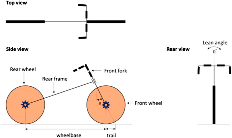
FIGURE 1. Basic parts and terminologies of a two-wheeler.
Sharp (Sharp, 1976; Sharp, 1978; Sharp, 1985; Sharp, 2001) has written previous assessments on two-wheeled single-track vehicles that emphasize on dynamics and control. He provides state of art reviews across time, focusing on motorbike stability, control, and steering reflexes. Furthermore, Limebeer and Sharp (Limebeer and Sharp, 2006) present a historical review of numerous bicycle and motorbike models and control theories. Popov et al. (Popov et al., 2010) examine rider models and steering control in bikes. Meijaard et al. (Meijaard et al., 2007) give a historical review of bicycle dynamics, focusing on linearized equations of motion for bicycle balance and steering. Sharp (Sharp, 2008) provides a synopsis of bicycle dynamics and control, while Kooijman et al. (Kooijman et al., 2011) provide a historical review of bicycle self-stabilization. Following that, Schwab and Meijaard (Schwab and Meijaard, 2013) and Kooijman and Schwab (Kooijman and Schwab, 2013) provide a complete discussion of bicycle dynamics and rider control. A more recent assessment is required because various research have been published in recent years, particularly those concentrating on experimental validations of suggested balancing and control systems for self-balancing two-wheeled single-track vehicles.
There are four basic ways used in the literature to establish self-balance in a two-wheeler: control moment gyroscope (CMG), reaction wheel control, steering control, and moving mass control. Furthermore, several studies combine these methodologies to suggest a self-balancing system. According to the literature survey, the most prominent categories used to achieve self-balance are control moment gyroscope and steering control. Some ways are better suited for balancing when the two-wheeler is stationary, while others are better suited for balancing while in motion.
CMG is only utilized for self-balancing while the two-wheeler is stationary or traveling at modest speeds (He and Zhao, 2015; Jin et al., 2015; Chi and Chou, 2016; Gattringer et al., 2018; Jain et al., 2020). This technique is inefficient at high speeds because it demands constant energy consumption from the CMG’s continuously rotating flywheel. As a result, continual power supply and considerable energy usage are required. As steering control is the most popular method for achieving balance when in motion (Xiong et al., 2018; Yu and Zhao, 2018; Andersson et al., 2019; Yeh et al., 2019; Wang et al., 2020), it is not possible to achieve balance while stationary. Reaction wheel control (Owczarkowski et al., 2019; Chiu and Wu, 2020; Cook and Zhang, 2020; Vu and Nguyen, 2020; Patil et al., 2021) is only appropriate for small scale lightweight two-wheelers which is not appropriate when high torque is required. The moving mass approach necessitates significant controller gains and, in general, necessitates the use of an auxiliary system to achieve self-balancing (Yamakita and Utano, 2005; Yamakita et al., 2006; Murayama and Yamakita, 2007; Keo and Masaki, 2008). The combination of two or more methodologies raises the complexity and demand for resources, as well as the operating costs and computational power.
A. Alzaydi (Alzaydi, 2023) work delves deeper into the workings of the controller and tests its methodology on a full-scale motorbike, whereas the current work continues A. Alzaydi work by providing the system’s mathematical modeling and a more holistic view, anchoring its solution within the broader narrative of two-wheeler self-balancing evolution. The current paper depicts the mathematical detailed model for a small-scale bike model (inverted pendulum) as well as the entire full-scale bike. A dynamic mathematical model employing a state space method is discussed, demonstrating the dynamic response of the bike and the controller’s influence.
The goal of this work is to come up with a novel technique for self-balancing. Two electric ducted fan (EDF) motors are oriented in opposite directions such that they propel air against the direction of fall and therefore preserve equilibrium. When these motors are given two degrees of freedom, the two-wheeler propels ahead while simultaneously reducing the overall weight of the two-wheeler while retaining stability. To the best of the authors’ knowledge, there has not been any research conducted on a system that can provide propulsion and weight reduction while also achieving self-balancing simultaneously.
In comparison the traditional techniques with the proposed approach, the electric ducted fan (EDF) motors will not run continuously at high speeds, resulting in a significant reduction in energy demand. It has the ability to self-balance a two-wheeler when it is stationary. The torque in the proposed technique may be adjusted by moving the EDF motors to different heights above the ground. The amount of torque required to ensure stability rises as these motors are placed higher, and vice versa. Thus, the proposed design solves the torque limitation problem. An independent technique to self-balancing is sought, and this work proposes such a methodology to achieve self-balancing employing EDF motors.
Based on the literature, Proportional-Integral-Differential (PID) controller is the most extensively utilized control system for the previous approaches and demonstrates solid performance in achieving self-stability. It is also less difficult to implement than the other controllers, so PID controller is used in the current study.
While the paper reviews traditional self-balancing techniques, such as control moment gyroscope (CMG), reaction wheel control, steering control, and moving mass control, it introduces the unique approach of utilizing electric ducted fans. This method, combined with the Proportional-Integral-Differential arducopter controller, ensures the vehicle remains at an upright 0° lean angle. The detailed explanation of mathematical modeling, design, and fabrication also sets this work apart. The potential to apply this technique to larger vehicles highlights the future applicability and broad implications of this novel approach.
The core concepts of the unique self-balancing system built for two-wheeled vehicle are presented in this part. Some of the principles covered include PID control system execution and controller design required, and so on. Additionally, the suggested self-balancing automobile, with two wheels, concept is evaluated on a small scale platform before being deployed on a big scale two-wheeler. This section depicts all of the mathematical modeling, mechanical and electrical parts designs for both the small size platform and the big scale two-wheeler, as well as the findings and comments for the completed experimental tests.
The inverted pendulum model is one of the most commonly used models in the literature for a vehicle with two wheels (Yeh et al., 2019; Patil et al., 2021; Vu and Nguyen, 2020). The two-wheeler is thought to pivot where the tires make contact with the ground. As a result, a corrective force (F) as shown in Figure 2 is required to self-balance the two wheels vehicle in an upright position with a zero degrees lean angle. It should be noted that this force does not change direction in relation to the pivoting of the two wheels vehicle and is always vertical to the vehicle frame, as shown in Figure 2. As seen in the literature, this corrective force could be delivered in a variety of methods to accomplish self-balance, and the current study proposes a novel technique to provide this force and achieve self-balance.
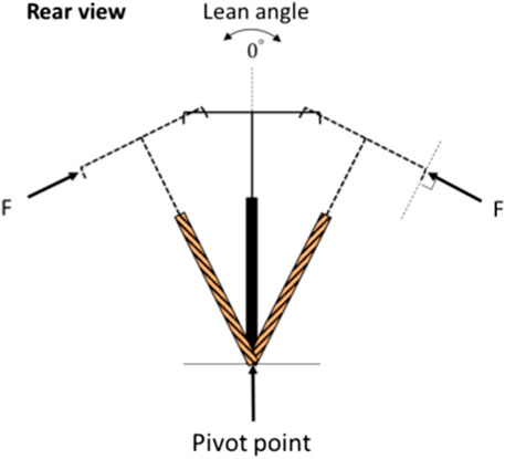
FIGURE 2. The amount of force necessary to keep the two-wheeler upright.
The design includes two opposing-facing EDF motors fitted on the motorbike, as shown in Figure 3A. To put it simply, these engines drive air in the opposing direction of gravity in order to maintain balance. A control system is necessary to send pulse width modulation (PWM) impulses to the EDF drives in order to adjust the rotational speed of the fan and control the quantity of propelled airflow (thrust). Further, even though the currents in the two EDF motors are equivalent in the upright position, a control system is required. This similar current source should give equal RPMs to generate the same forces, but slight variations in the shape of the EDF motor propellers and the overall layout of the ducts cause a disparity in force produced at the same currents. Consequently, a system of controls is necessary to control the RPMs of the propellers and provide adequate push to maintain the motorbike upright. A PID control system is utilized to control the rotation speed of the EDF propellers to attain the self-balancing of the motorbike.
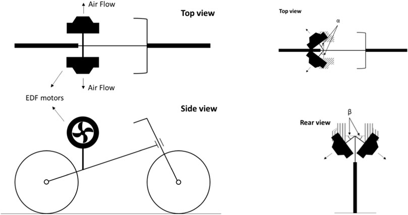
FIGURE 3. Suggested scheme to achieve self-balance using EDF motors.
If the two fitted EDF propellers could turn by angles α and β, as indicated in Figure 3B, the motorbike might be moved forward while being self-balanced. As a result of modify the α value, some of the energy required to propel the bike ahead will be saved. Moreover, tilting angle β minimizes the weight of the motorbike, which is especially beneficial while hauling heavy loads. Essentially, reducing the motorbike’s weight would decrease the driving energy usage while preserving self-balance, but it is important to maintain enough friction force between the wheels and the ground to avoid slippage. To the best of the authors’ knowledge, no study has been conducted that has resulted in a system capable of providing concurrent propulsion and weight loss while maintaining self-balance.
It is worth mentioning that using EDF is not familiar in balancing bikes but many researches have been conducted on using similar technologies in balancing inverted pendulums representing different systems. Shenawa and Lindholm in their degree project at the Swedish Royal Institute of Technology (KTH), in reference (Shenawa and Lindholm, 2022) they discuss the problem balancing a mono-wheel robot using EDF system. They used PID controller and Gyroscope system. On the other hand, ducted fan flying objects was discussed in (Miwa et al., 2012) for helicopters and flying systems. The system has been controlled using PID controller showing its benefits over PD one. The system is called thrust vectoring because it was used for the direction of the flying objects which much more complicated than our case.
Prior to implementing the suggested unique self-balancing system on a large scale powered two-wheeler, the proposed self-balancing design and control are tested on a small scale for proof of concept, i.e., validation. This section describes the mathematical modeling, mechanical and electrical parts designs, as well as the experimental tests of the PID control system on a small scale (dummy) model. The self-balancing system for the small scale model is constructed as an inverted pendulum with the same configuration of using opposing faced EDF motors, see Figure 4. However, in place of the EDF motors, two brushless motors with corresponding propellers are employed to deliver thrusts identical to those outlined in conceptualization (Section 2.1). There is no difference in the operation of a brushless motor and an EDF motor because both employ the same mechanism to accept voltage signals from the power supply. As a result, using brushless motors instead of EDF motors for testing on the dummy platform should nearly mimic the results for the full scale model of a two-wheeler. Furthermore, inverted pendulum system dynamics can be employed to represent a two-wheeler, this is discussed in (Yeh et al., 2019; Patil et al., 2021; Vu and Nguyen, 2020). As a result, testing the proposed innovative self-balancing system on a small scale model created as an inverted pendulum system provides insight into the proposed unique self-balancing system and acts as a crucial step in validating the proposed self-balancing system.
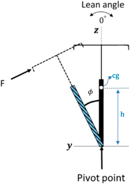
FIGURE 4. Inverted pendulum bike model.
Assume h is the vertical distance from the origin point to the center of gravity, cg, (h = 0.3 m),
To have the mathematical modeling of the inverted pendulum bike model, the summation of moments about x-axis results
which gives
As shown in Figure 5, the mechanical assembly of a small scale inverted pendulum model consists of five pieces. A base, single degree of freedom joint, lower socket, top frame, and carbon fiber tube are among the five components. A single degree of freedom joint connects the base to the lower socket, allowing the lower socket to rotate in one degree of freedom. A 50-cm-long carbon fiber tube is pressed into both the lower socket and the upper frame, creating an inverted pendulum system. Furthermore, stoppers are inserted on either side of the dummy model’s carbon fiber tube to ensure that the brushless motors’ propellers do not collide with the base. These stoppers indicate the maximum limitations specified for the roll angle, which is approximately 30°. This is higher than the big scale model, where the lean angle limit is designed to not exceed 20° because normal two-wheeler driving does not exceed lean angles larger than this amount.
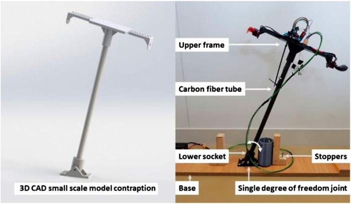
FIGURE 5. Mechanical assembly of the small scale model showing the mechanism on CAD on the left and manufactured and assembled on the right.
Keeping the maximum limits for the dummy model greater than the big scale model is self-explanatory because it allows simulation of the mechanism with higher values of parameters like the maximum permissible roll angle. The single degree of freedom joint, lower socket, and upper frame are 3D printed with PLA plastic. The carbon fiber tube is commercially available, while the wood base is handmade.
The dummy model’s electrical components include electronic speed control (ESC), brushless motors with propellers, an arducopter controller, and a power supply. The ESC is an electronic circuit that controls the speed of brushless motors using PWM signals from the arducopter controller. The purpose of this speed regulation is to achieve precise thrust values from the brushless motors in order to self-balance the inverted pendulum. The type of ESC utilized is determined on the brushless motors used. In current study situation, a 2212 920 KV brushless motor is used, which implies a 30 A ESC, but a higher current rating is chosen to avoid damage to the electrical components of either the ESC or the brushless motors, and the chosen ESC is iPeaka 35A DShot 4 IN 1 BLHELI_S. To power the circuit, the ESC wiring (Figure 6) requires a 4S LiPo battery to be connected. The PWM wire is connected to the arducopter controller, and the three wires with 3.5 mm bullet connectors are attached in any order to the brushless motors. If the motor spins in the opposite direction of the desired rotation, any two of these wires must be changed.
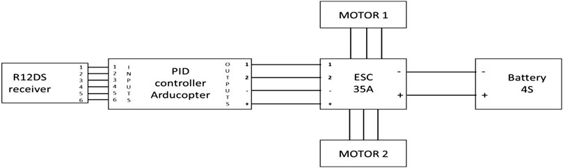
FIGURE 6. Wiring diagram for the small scale model.
The mechanical and electrical components are integrated, and the dummy model is tested by using a PID control system to achieve the proposed self-balancing design. Figure 7 shows the unbalanced state with the controller turned off and the roll angle set to 23.9°. In addition, the self-balancing state is depicted in the same picture, where the roll angle is around 0°, which is the required lean angle. Experiments are carried out in order to achieve a good response from the PID controller in order to stabilize the system at the specified lean angle.
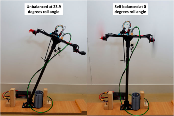
FIGURE 7. The small scale model unbalanced on the left and self-balanced on the right when the system is switched on.
The controller’s response is monitored after two distinct tests are run on the fake model. The first experiment seeks to achieve self-balance from the inverted pendulum’s imbalanced position at 23.9°. Figure 8 depicts the results of this test compared with the theoretical response that shows a very good agreement. It shows that the suggested control system successfully stabilizes the small scale model at the appropriate lean angle. It can be seen that the mechanism oscillates steadily between −0.2 and 0.2° roll angle. This oscillation is caused by friction between the single degree of freedom joint and the lower socket. It should be noted that the PID values were obtained after several trials in order to achieve the best results.
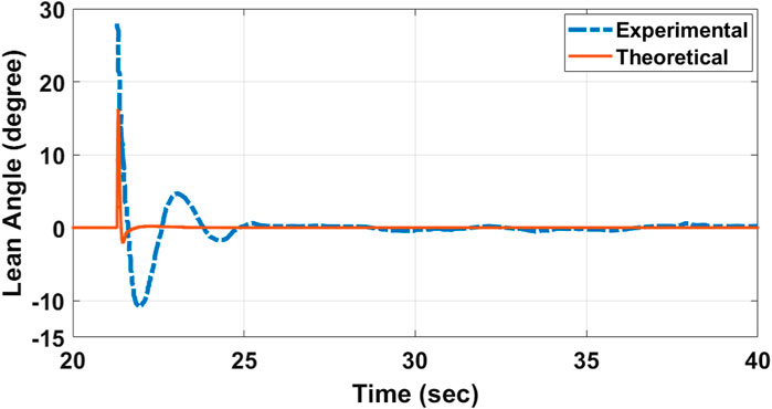
FIGURE 8. Theoretical and experimental responses of the PID controller when the system is self-balanced from rest showing lean angle vs. time.
The second experiment puts the constructed controller to the test against external disturbances. At the times t = 34 and t = 46.5 s, a random force is applied theoretically and experimentally to the dummy model. The period when these two forces are applied is denoted by the symbol * in Figure 9, which depicts the controller’s response. Clearly, the system operates admirably in bringing the inverted pendulum model to its equilibrium self-balanced upright posture with little oscillations. In conclusion, the theoretical and experimental results of the two trials match well to each other’s and the two trials confirm and validate the proposed unique concept for attaining self-balancing of two wheels single-track automobiles. The results are not identical due to real-world complexities. Theoretical models simplify real-world scenarios, and actuators in these models may not account for real-world inefficiencies, delays, or nonlinearities. Moreover, feedback mechanisms in real systems, like sensors, can introduce errors not present in theoretical models.
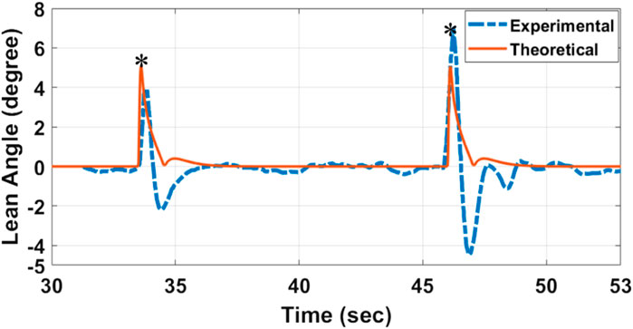
FIGURE 9. Theoretical and experimental responses of the PID controller (lean angle vs. time) when the self-balancing system is tested against external disturbances.
After successfully testing the suggested controller architecture for self-balancing systems on a small-size model, the principle is used in a bigger framework, namely, a motorbike. The motorbike selected is a gas-powered Suzuki AN 125 with an automatic transmission. Because of the system’s large size, careful mechanical and electrical design is required to install the self-balancing system on this motorbike. To demonstrate the test findings, the parts that follow this design are presented in further detail. The identical procedure as for the small-scale model is utilized to implement the self-balancing system on the full-scale motorbike.
The thrust required for stabilizing a two-wheeled vehicle, especially a motorbike, using electric ducted fans (EDFs) is a complex calculation. The concept of using EDFs relies on counteracting the gravitational pull (especially during a fall or tilt) with the thrust from the EDFs.
Force of gravity on the Bike is
Given the text, the inverted pendulum model (a widely recognized model for two-wheelers) can be used to determine the corrective force required to stabilize the vehicle. This corrective force, F, is applied perpendicular to the frame of the motorbike, counteracting the gravitational torque. To achieve stabilization, the torque produced by the EDFs should equal the gravitational torque.
For stabilization, the force or thrust exerted by one EDF:
Eq. (3) provides an estimate of the thrust required from each EDF to stabilize the motorbike. Adjusting the height Z (by placing the EDFs higher) changes the balancing torque.
The idea of adjusting the height of the EDFs provides a dynamic method to regulate the balancing torque. A higher placement of the EDFs would require more torque (and thus thrust) to achieve the same stabilization as an EDF placed lower. This insight can be used to adjust the system’s responsiveness and efficiency.
The system’s stabilization relies on a combination of mechanical design, the positioning and performance of the EDFs, and the real-time feedback control achieved through the PID controller. The balance between these elements will determine the system’s effectiveness in maintaining the two-wheeler’s stability.
Consider the typical two-wheel drive bike with the geometry and dimensions shown in Figure 10. The origin point is taken on the point of contact of rear wheel with the ground, the horizontal direction of drive is the x-axis and the vertical direction is the z-axis which leaves the normal horizontal direction for the y-axis. Table 1 shows the different dimensions and notations for the two-wheel bike.
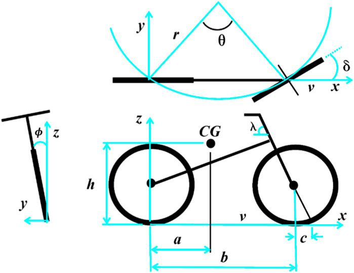
FIGURE 10. Geometry and dimensions of a typical bike.
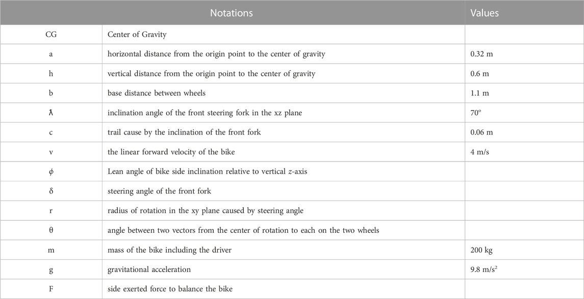
TABLE 1. Different dimensions notations for the typical two-wheel drive bike.
To derive the mathematical model, firstly the moments that caused by the different forces about the x-axis has been derived.
• Moment due to the force exerted on the side of bike to balance it (
• Moment due to the bike’s weight (
• Moment due to centrifugal force of rotation (
• Moment due to change of center of gravity during rotation (
• Moment due to inertia (
Since
So,
Taking summation of moments about x-axis results
Dividing Eq. (6) by mh2 and Knowing that tanδ = δ and
The previous equation represents the mathematical model which can be transferred into state space model to be simulated on Matlab. Taking the state variables
The following results (Figures 11, 12) have been obtained on MatLab while implementing a PID controller. The PID parameter have been tuned using trial and error. Figures 11, 12 show that the suggested control system successfully stabilizes the two-wheel bike model at the appropriate lean angle. In addition, the system tracks square and sine responses successfully.
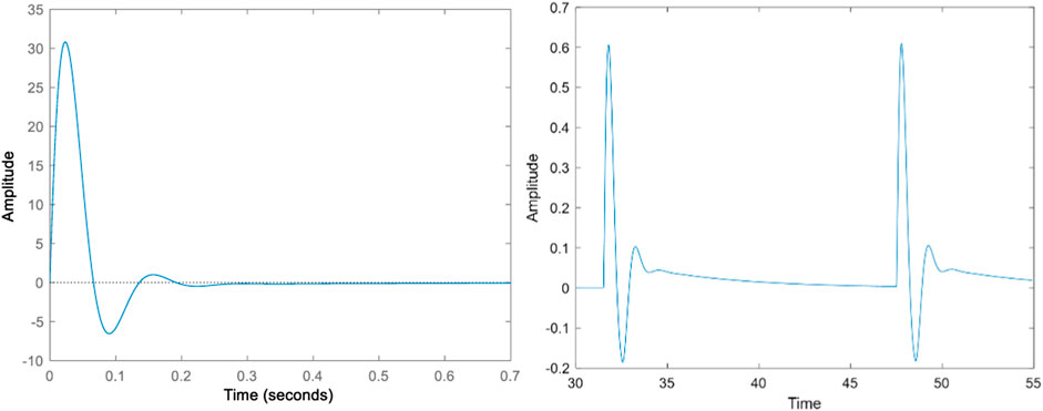
FIGURE 11. Impulsive and pulse train responses for the bike model (Lean angle in degrees Vs. time in seconds).
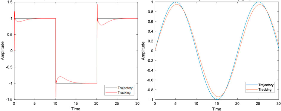
FIGURE 12. Square and sine tracking responses for the bike model (Lean angle in degrees Vs. time in seconds).
The structural elements for the self-balancing system be made up of many parts (Alzaydi, 2023), including a custom-designed base, pipes, a vibration sheet for the controller (arducopter PID), EDF holders, and additional components used to link all of previous elements together in order to make an integrated assembly. The angles α and β of the EDFs are assumed to be zeros. The entire unit is seen in Figure 13 positioned at the back of the motorbike. A specially manufactured base plate is linked to the metal base by two reversed U-shaped 3D printed supports, as illustrated in Figure 13. Because this base plate supports the entire system, a dependable design is required to endure stresses induced by the operation of the EDF motors. The foundation plate is created first, as seen in Figures 14A, 3D manufactured with PLA plastic infill of 20%. It is weighed against the most force that acts on the carbon fiber pipe inserts as a result of EDF motor force. Because the ideal force from the EDF propellers (9 kg) is distributed over four carbon fiber pipes, the force thus generated works on the walls of the carbon fiber pipe plugs in a horizontal direction which is parallel to the base plate), producing a near-maximum load of 2.25 kg. Due to the poor design of the carbon fiber pipe inserts and low percentage infill, the PLA plastic base plate with 20% infill failed. As a result, rebuilding the base plate by adding ribs in weak locations, adjusting the heights and thicknesses of the tube inserts, and 3D printing using PLA + plastic material with more than 60% infill resulted in a more robust base plate that can bear loads generated by EDF motors. As shown in Figure 14B, the EDF motor mounts are 3D printed, with four carbon fiber pipes joined together by press fitting. Two carbon fiber tubes link to the top ends of pipes connecting to the base plate by clicking into position on the upper half of the frame. This top structure was developed in CAD and 3D printed.
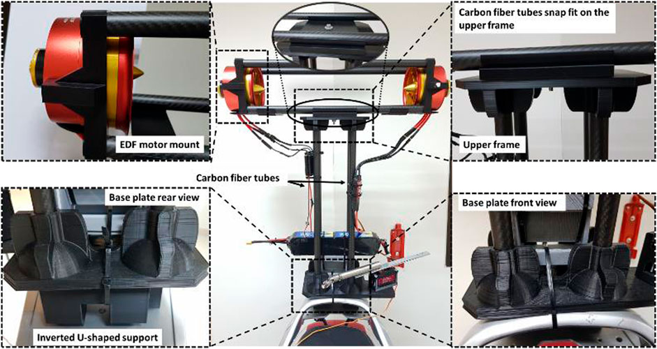
FIGURE 13. Mechanical components arrangement for the self-balancing system, which is installed at the back of the motorbike.
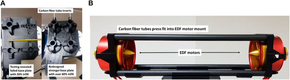
FIGURE 14. (A) Fabricated base plate (B) The top of the arrangement displays EDF motor mounts with carbon fiber pipes pressed into the motor mounts.
Inertial Measurement Unit (IMU) sensor and a nonlinear complementary filter are used to measure the bike’s lean angles. These angles, indicating the bike’s tilt, are crucial feedback for the PID arducopter controller. When a discrepancy between the desired (upright) and actual lean angle arises, the controller activates the Electric Ducted Fans (EDF) to counteract the tilt and stabilize the bike. This continuous monitoring and correction is a feedback loop characteristic of PID systems. Figure 15A depicts a wiring design for a large scale model’s self-balancing system (Alzaydi, 2023). PWM signals are sent to the EDF motors by the PID arducopter controller via the selected ESCs. A radio transmitter-receiver combination (Radio link AT10 transmitter paired with R12DS receiver) is also utilized to arm and deactivate the controller and control the lowest possible thrust values delivered to the EDF motors via pulse width modulation (PWM) signals.
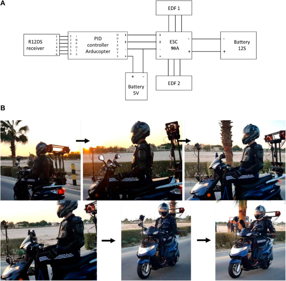
FIGURE 15. (A) Wiring diagram for the self-balancing system of large scale model (Alzaydi, 2023), (B) Testing of the proposed balancing system on a motorbike while in motion.
The recommended concept of self-balancing using a PID controller is tested against a full-scale model (motorbike) by assembling the mechanical and electrical parts as specified. Figure 15B depicts a test in which the suggested self-balancing system stabilizes the two-wheeler in an upright position while the vehicle is in motion. Although bikes naturally stabilize at higher speeds, this system’s primary aim is to maintain balance at low speeds or when stationary, a notable challenge. The current work showcased various tests, from theoretical simulations to small-scale and full-scale motorbike experiments. While the “hands-free” demonstration may not be conclusive proof of the system’s effectiveness, it is indicative of its capabilities. Figure 15B depicts a series of photos of a two-wheeler going in a straight path while the rider’s hands are kept away from the steering handle during the test. As seen, the suggested self-balancing technology keeps the two-wheeler balanced and upright. The dynamics of the rider-vehicle interactions during the test could have influenced the outcomes to preserve stability. These dynamics were not taken into account when designing the proposed paradigm. Due to resource constraints, a rail frame to guard the body of the two-wheeler to prevent damage in the event the vehicle tips over and the robustness is required as a future research recommendation in order to conduct the test without a human rider and thus determine if the rider motorbike dynamics interactions played a role in successfully stabilizing the motorbike in the upright position.
The current work proposes a novel technique of self-balancing using a PID control system. Simply described, the design comprises of two EDF that propel air in the opposite direction of descent to maintain equilibrium. Allowing these motors to move in two degrees of freedom allows the EDF motors to propel and lower the weight of the two-wheeler while retaining stability.
Mathematical modeling, mechanical part design and fabrication, electrical component design, and control system design are the four primary steps in the methodology that have been followed. All components for the driving control, small scale and large scale self-balancing platform are designed and manufactured during the mechanical parts design and manufacturing stage. Following that, in the electrical components design stage, components such as ESCs, servo motors, wiring, brushless motors, power supply, and PID controller are selected for the small scale, and large scale self-balancing platforms.
This paper offered an innovative method for achieving self-balancing of two-wheeled single-track vehicles using EDF motors. Simply described, these motors drive air against the direction of fall in order to maintain balance. A PID control system is employed to manage the thrust of the EDF motors based on the two-wheeler’s instantaneous lean angle. The proposed PID controller is tested theoretically and experimentally on a small scale model to validate the developed concept of self-balancing using EDF motors. Two tests were executed successfully: testing from unbalanced 23.9° lean angle to self-balance at upright zero degrees lean angle and testing robustness against external disturbances. After achieving effective results on the small scale model, the proposed concept is evaluated on a large scale model (motorbike) by deriving its mathematical modeling then implementing and designing the mechanical and electrical components. A PID control system is employed theoretically to manage the thrust of the EDF motors based on the two-wheeler’s instantaneous lean angle. The suggested control system successfully stabilizes the two-wheel bike model against the external forces. A practical test is conducted on a two-wheeler motorbike and the suggested self-balancing system stabilizes the two-wheeler in an upright position while it is in motion. The two-wheeler motorbike was going successfully in a straight path while the rider’s hands are kept away from the steering handle during the test.
The original contributions presented in the study are included in the article/supplementary material, further inquiries can be directed to the corresponding author.
MH: Data curation, Formal Analysis, Investigation, Software, Supervision, Validation, Writing–original draft. AA: Conceptualization, Data curation, Formal Analysis, Methodology, Project administration, Validation, Writing–review and editing. AAH: Formal Analysis, Software, Supervision, Validation, Writing–review and editing.
The author(s) declare that no financial support was received for the research, authorship,and/or publication of this article.
The authors are appreciative of the support given by the Deanship of Research (Project: DF181030), the Interdisciplinary Research Center for Intelligent Manufacturing and Robotics at King Fahd University of Petroleum and Minerals (KFUPM). In addition, the authors are appreciative of the support given by Birzeit University.
The authors declare that the research was conducted in the absence of any commercial or financial relationships that could be construed as a potential conflict of interest.
All claims expressed in this article are solely those of the authors and do not necessarily represent those of their affiliated organizations, or those of the publisher, the editors and the reviewers. Any product that may be evaluated in this article, or claim that may be made by its manufacturer, is not guaranteed or endorsed by the publisher.
Alzaydi, A. (2023). “Self-balancing system and control design for two-wheeled single-track vehicles,” in 2023 20th Learning and Technology Conference (L&T) (IEEE), 109–113.
Anderson, J. M., Kalra, N., and Stanley, K. D. (2014). Paul sorensen, constantine samaras, and oluwatobi A. Oluwatola. “Autonomous vehicle technology: a guide for policymakers. Rand Corporation.
Andersson, T., Persson, N., Fattouh, A., and Ekstrom, M. C. (2019). “A loop shaping method for stabilising a riderless bicycle,” in 2019 European Conference on Mobile Robots, ECMR 2019 - Proceedings. doi:10.1109/ECMR.2019.8870965
Baumann, M., Bächle, T., Buchholz, M., and Dietmayer, K. (2016b). Model-based corner braking control for electric motorcycles. IFAC-PapersOnLine 49 (11), 291–296. doi:10.1016/j.ifacol.2016.08.044
Baumann, M., Buchholz, M., and Dietmayer, K. (2016a). A two-wheel driven power train for improved safety and efficiency in electric motorbikes. World Electr. Veh. J. 8 (1), 102–111. doi:10.3390/wevj8010102
Chi, C. H., and Chou, J. J. (2016). “Riderless bicycle with gyroscopic balancer controlled by FSMC and AFSMC,” in International Congress on Ultra Modern Telecommunications and Control Systems and Workshops, 150–157. doi:10.1109/ICUMT.2015.7382420
Chiu, C. H., and Wu, C. Y. (2020). Bicycle robot balance control based on a robust intelligent controller. IEEE Access 8, 84837–84849. doi:10.1109/ACCESS.2020.2992792
Claypool, H., Bin-Nun, A., and Gerlach, J. (2017). Self-driving cars: the impact on people with disabilities. Newton, MA: Ruderman Family Foundation.
Cook, G., and Zhang, F. (2020). Mobile robots: navigation, control and sensing, surface robots and AUVs. 2nd Edition. John Wiley & Sons, Ltd.
Gattringer, H., Reiter, A., Müller, A., Wagner, D., and Mauernböck, T. (2018). Dynamical modeling and LQR control of a gyroscopically stabilized bicycle. PAMM 18 (1). doi:10.1002/pamm.201800406
He, J., and Zhao, M. (2015). Control system design of self-balanced bicycles by control moment gyroscope. Lecture Notes in Electrical Engineering 338, 205–214. Springer Verlag. doi:10.1007/978-3-662-46466-3_21
Jain, A., Bhaskar, S., Nandanwar, K., and Bansal, H. O. (2020). Self-balancing of a bike using gyroscopic force and PID controller, Advances in intelligent systems and computing, 989. Springer Verlag, 807–817.
Jin, H., Yang, D., Liu, Z., Zang, X., Li, G., and Zhu, Y. (2015). “A gyroscope-based inverted pendulum with application to posture stabilization of bicycle vehicle,” in 2015 IEEE International Conference on Robotics and Biomimetics (IEEE-ROBIO 2015), 2103–2108. doi:10.1109/ROBIO.2015.7419084
Keo, L., and Masaki, Y. (2008). “Trajectory control for an autonomous bicycle with balancer,” in 2008 IEEE/ASME International Conference on Advanced Intelligent Mechatronics, 676–681. doi:10.1109/AIM.2008.4601741
Kooijman, J. D. G., Meijaard, J. P., Papadopoulos, J. M., Ruina, A., and Schwab, A. L. (2011). A bicycle can be self-stable without gyroscopic or caster effects. Sci. (80-. ) 332 (6027), 339–342. doi:10.1126/science.1201959
Kooijman, J. D. G., and Schwab, A. L. (2013). A review on bicycle and motorcycle rider control with a perspective on handling qualities. Veh. Syst. Dyn. 51 (11), 1722–1764. doi:10.1080/00423114.2013.824990
Limebeer, D. J., and Sharp, R. S. (2006). Single-track vehicle modeling and control: bicycles, motorbikes, and models. IEEE Control Syst. 26 (5), 34–61. doi:10.1109/MCS.2006.1700044
Lucci, C., Marra, M., Huertas-Leyva, P., Baldanzini, N., and Savino, G. (2021). Investigating the feasibility of motorcycle autonomous emergency braking (MAEB): design criteria for new experiments to field test automatic braking. MethodsX 8, 101225. doi:10.1016/j.mex.2021.101225
Meijaard, J. P., Papadopoulos, J. M., Ruina, A., and Schwab, A. L., (2007). Linearized dynamics equations for the balance and steer of a bicycle: a benchmark and review,” Proc. R. Soc. A Math. Phys. Eng. Sci., vol. 463, 1955–1982. doi:10.1098/rspa.2007.1857
Meijaard, J. P., and Schwab, A. L. (2008). “Linearized equations for an extended bicycle model,” in III European Conference on Computational Mechanics (Dordrecht: Springer Netherlands), 772.
Milakis, D., Van Arem, B., and Van Wee, B. (2017). Policy and society related implications of automated driving: a review of literature and directions for future research. J. Intelligent Transp. Syst. 21 (4), 324–348. doi:10.1080/15472450.2017.1291351
Miwa, M., Shigematsu, Y., and Yamashita, T. (2012). Control of ducted fan flying object using thrust vectoring. J. Syst. Des. Dyn. 6 (3), 322–334. doi:10.1299/jsdd.6.322
Murayama, A., and Yamakita, M. (2007). “Development of autonomous bike robot with balancer,” in Proceedings of the SICE Annual Conference, 1048–1052. doi:10.1109/SICE.2007.4421139
Owczarkowski, A., Horla, D., and Zietkiewicz, J. (2019). Introduction of feedback linearization to robust LQR and LQI control – analysis of results from an unmanned bicycle robot with reaction wheel. Asian J. Control 21 (2), 1028–1040. doi:10.1002/asjc.1773
Panzani, G., Corno, M., and Savaresi, S. M. (2013). On adaptive electronic throttle control for sport motorcycles. Control Eng. Pract. 21 (1), 42–53. doi:10.1016/j.conengprac.2012.09.007
Patil, O., Jadhav, S., and Ramakrishnan, R. (2021). “Development of reaction wheel controlled self-balancing bicycle for improving vehicle stability control,” in Lecture notes in mechanical engineering (Springer Science and Business Media Deutschland GmbH), 187–195.
Popov, A. A., Rowell, S., and Meijaard, J. P. (2010). A review on motorcycle and rider modelling for steering control. Veh. Syst. Dyn. 48 (6), 775–792. doi:10.1080/00423110903033393
Schwab, A. L., and Meijaard, J. P. (2013). A review on bicycle dynamics and rider control. Veh. Syst. Dyn. 51 (7), 1059–1090. doi:10.1080/00423114.2013.793365
Sharp, R. S. (1976). The dynamics of single track vehicles. Veh. Syst. Dyn. 5 (1–2), 67–77. doi:10.1080/00423117508968406
Sharp, R. S. (1978). A review of motorcycle steering behavior and straight line stability characteristics. SAE Tech. Pap., 780303. doi:10.4271/780303
Sharp, R. S. (2008). On the stability and control of the bicycle. Appl. Mech. Rev. 61 (6), 0608031–06080324. doi:10.1115/1.2983014
Sharp, R. S. (1985). The lateral dynamics of motorcycles and bicycles. Veh. Syst. Dyn. 14 (4–6), 265–283. doi:10.1080/00423118508968834
Sharp, R. S. (2001). Stability, control and steering responses of motorcycles. Veh. Syst. Dyn. 35 (5), 291–318. doi:10.1076/vesd.35.4.291.2042
Shenawa, A., and Lindholm, V. (2022). Degree project in technology. Royal Institute of Technology.Balancing monowheel using electric ducted fans: a study on designing and programming a monowheeled robot.
Surana, A., Jeffs, J., and Dinh, T. Q. (2020). “Accident prevention in motorcycles with 3 dimensional fuzzy logic traction control system,” in 2020 8th International Conference on Control, Mechatronics and Automation, ICCMA, 156–161. doi:10.1109/ICCMA51325.2020.9301500
Vu, N. K., and Nguyen, H. Q. (2020). Balancing control of two-wheel bicycle problems. Math. Probl. Eng. 2020, 1–12. doi:10.1155/2020/6724382
Wang, Z., Wang, Y., Zhang, B., Wang, G., Liu, T., Yi, J., et al. (2020). “Development of a two-wheel steering unmanned bicycle: simulation and experimental study,” in IEEE/ASME International Conference on Advanced Intelligent Mechatronics, AIM, 119–124. doi:10.1109/AIM43001.2020.9158912
Winter, D., Joost, C. F., Happee, R., Martens, M. H., and Stanton, N. A. (2014). Effects of adaptive cruise control and highly automated driving on workload and situation awareness: a review of the empirical evidence. Transp. Res. part F traffic Psychol. Behav. 27, 196–217. doi:10.1016/j.trf.2014.06.016
Xiong, C., Huang, Z., Gu, W., Pan, Q., Liu, Y., Li, X., Wang, E. X., et al. (2018). “Static balancing of robotic bicycle through nonlinear modeling and control,” in In 2018 3rd International Conference on Robotics and Automation Engineering (ICRAE), 24–28. doi:10.1109/ICRAE.2018.8586765
Yamakita, M., and Utano, A. (2005). “Automatic control of bicycles with a balancer,” in Proceedings, 2005 IEEE/ASME International Conference on Advanced Intelligent Mechatronics, 1245–1250. doi:10.1109/AIM.2005.1511181
Yamakita, M., Utano, A., and Sekiguchi, K. (2006). “Experimental study of automatic control of bicycle with balancer,” in 2006 IEEE/RSJ International Conference on Intelligent Robots and Systems, 5606–5611. doi:10.1109/IROS.2006.282281
Yeh, T. J., Lu, H. T., and Tseng, P. H. (2019). “Balancing control of a self-driving bicycle,” in ICINCO 2019 - Proceedings of the 16th International Conference on Informatics in Control, Automation and Robotics, 34–41. doi:10.5220/0007810600340041
Keywords: two-wheelers, motorbikes control, electric ducted fans, stability, PID
Citation: Horoub M, Alzaydi A and Hanieh AA (2023) Electric ducted fan controller and self-balancing system for two-wheeler motorbike. Front. Mech. Eng 9:1284879. doi: 10.3389/fmech.2023.1284879
Received: 29 August 2023; Accepted: 30 October 2023;
Published: 15 November 2023.
Edited by:
Renato Vidoni, Free University of Bozen-Bolzano, ItalyReviewed by:
Amin Mahmoudzadeh Andwari, University of Oulu, FinlandCopyright © 2023 Horoub, Alzaydi and Hanieh. This is an open-access article distributed under the terms of the Creative Commons Attribution License (CC BY). The use, distribution or reproduction in other forums is permitted, provided the original author(s) and the copyright owner(s) are credited and that the original publication in this journal is cited, in accordance with accepted academic practice. No use, distribution or reproduction is permitted which does not comply with these terms.
*Correspondence: Mamon Horoub, bWhvcm91YkBiaXJ6ZWl0LmVkdQ==
Disclaimer: All claims expressed in this article are solely those of the authors and do not necessarily represent those of their affiliated organizations, or those of the publisher, the editors and the reviewers. Any product that may be evaluated in this article or claim that may be made by its manufacturer is not guaranteed or endorsed by the publisher.
Research integrity at Frontiers
Learn more about the work of our research integrity team to safeguard the quality of each article we publish.