 B. Bawono
 T. Yuniarto1
 S. Felasari
- 1Department of Industrial Engineering, Universitas Atma Jaya Yogyakarta, Yogyakarta, Indonesia
- 2Department of Architecture Engineering, Universitas Atma Jaya Yogyakarta, Yogyakarta, Indonesia
- 3Division New Product Research and Development, Salatiga, Indonesia
Batik has been the cultural heritage of the Indonesian nation since the 17th century. On 2 October 2009, the United Nations Educational, Scientific, and Cultural Organization (UNESCO) designated Batik as part of Indonesia’s traditional clothing as Indonesia’s cultural heritage. This research proves that Batik is an attractive and artistic ornament of ceramic jewelry products. This ornament can increase the selling value and storytelling of the product. Naruna is a local handmade porcelain ceramic factory in Indonesia with excellence in unique colored tableware and consistently trying to develop new designs in ceramic jewelry. Modern technology in computer-based virtual design and machining on dining plate tableware with the Batik Kawung motif is also applied in this paper to obtain a master design for ceramic jewelry prints. The design stage begins with selecting ornament patterns with creative methods to form a 3D CAD model of ceramic jewelry using artistic Art CAM. The optimization of computer-aided manufacturing-based to obtain machining strategy using the software. The software is Autodesk Power Mill, whose NC Code can be directly manufactured on a CNC router machine. This combination can speed up the production process time to meet the production capacity at Naruna and get detailed, accurate, precise, and consistent textures and ornaments, thereby meeting NCS consumer demand for ceramic jewelry products. The simulation results of the two master print patterns are 141 h, 56 min, and 46 s; the machining time is estimated at 153 h. This research saves about 11 h of time processing. The resulting NC Code can be appropriately processed on a CNC router machine with a Mach 3 post-processor.
1 Introduction
People have always designed things. One of the most essential characteristics of human beings is that they make a wide range of tools and other artifacts to suit their purposes. Nowadays, it is not always a person who makes the artifact; machines make some artifacts with no direct human operator. These machines might be reasonably sophisticated numerically-controlled tools such as milling machines CNC and or 3D Print (McLaughlin, 1988a; McLaughlin, 1988b; Homer and Skaar, 1991; Oncea, 2013; Oncea et al., 2013; Othman, 2012; Zhang et al., 2018; Anggoro et al., 2021; Anggoro et al., 2022). In these cases, therefore, the final design specification before manufacturing might not be in the form of drawings but a string of digits stored on a disk or in computer software that controls the CNC machine’s actions. It is, therefore, possible to have a design process in which no final communication drawings are made, but the ultimate purpose of the design process remains the communication of proposals for a new artifact or a new development product (Cross, 2005).
Today, however, technology has become so advanced and sophisticated that one person cannot possibly be aware of all the intricacies of a single device or process. The concept of systems engineering thus has evolved; that is, technological problems are studied and solved by a technology team. Successful technology teams use the unique abilities of all team members to bring about a successful solution to a human need/The development engineer produces a concept or model that is passed on to the design engineer for converting into a device, process, or structure (see Figure 1). Like the development engineer, the designer is creative. This discussion process aims to get the best results from each design proposal and result product (Wright, 2002; Eide et al., 2012).
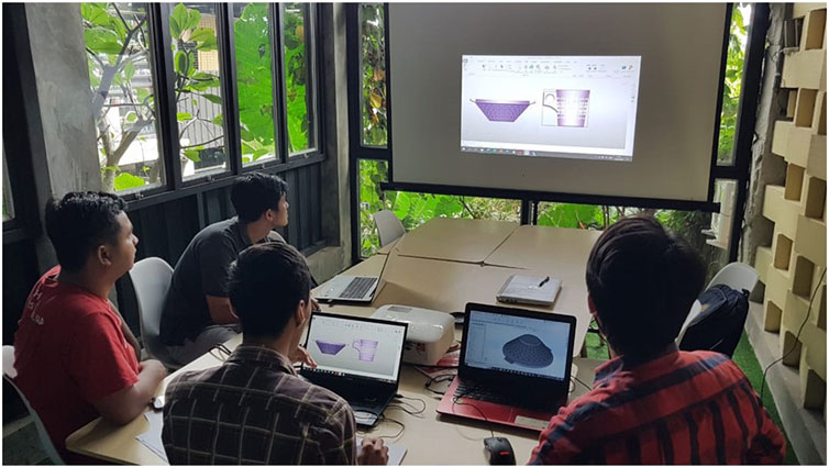
FIGURE 1. A team of design engineers ceramic reviewed a proposed design solution for the Batik Kawung motif that can be wrapped on the surface of tableware (plate, mug, teapot seat).
In e-Design, system designers create a solid model of a process innovation concept utilizing CAD tools, such as Autodesk Power Shape, Solid Works; MasterCAM; Rhinoceros; ArtCAM, Z-brush, and others. Simulations for quality performance, precision, and manufacture can be carried out using the product’s physical model presented in CAD. Engineering specialties and competence are used to manage design and development tasks and the cross-functional group. Based on a centralized computer-aided design prototype, simulation models can be derived using correct simplifying assumptions. However, for faster simulation model modifications, a one-way geometry that directs alterations from CAD models to simulation models must be built (Chang, 2015a; Chang, 2015b; Chang, 2015c; Anggoro et al., 2022). However, some of the researchers above have not conducted research on industrial product design simulations from CAD models to virtual machining in the ceramic industry, especially in jewelry products. The novelty of this paper is that it wants to explain the novelty of the stages of the design, manufacturing, and fabrication process of ceramic jewelry pendants with artistic CAD-based heritage motifs.
The ceramic industry, which produces a variety of tableware, sanitary, and wall tile products, has long been based on artistic crafts. Many elements of lines, arcs, and surfaces that designers design into ornamental patterns with contours by natural forms, flora, fauna, geometric elements, and ancient heritage buildings become porcelain ceramic products that have high selling value and aesthetics (Renzi, J., 2009). However, in Indonesia’s local and national ceramic industry, computers are mostly used for word processing, databases, records, payments, warehousing, and process monitoring (principles of administration and company management). The ceramic industry in Indonesia still applies a little computer technology in designing due to technological and cost constraints. Along with the development of information technology and CAD-CAM applications and manufacturing processes, several industries are increasingly interested in using computer technology (Anggoro et al., 2022); based on research previously, there has been no writing that discusses in detail the stages of virtual detain design and virtual machining custom in jewelry pendant ceramic products.
The adoption of computer-based design technology business for the design stage of new product innovation is still seen a bit because of the dependence on handmade technology. Difficulties arise when the customer requests a new ceramic product with repetitive embossed motifs that are precise, thorough, and capable of massive and mass production. This condition is also experienced by Naruna (one of the porcelain ceramic factories in Central Java, Indonesia) to develop new ceramic product designs such as tiles, walls, and jewelry. One of Naruna’s strengths is that handmade tableware products, custom, unique in color, and capable of self-fabrication, have penetrated national and international markets. Even in 2022, Naruna can export handmade and uniquely colored tableware products to more than 12 countries. The absence of modern technology owned by Naruna makes it challenging to meet the high demand for precision, accurate, and fast repetitive emboss patterned ceramic products, such as jewelry ceramics with Indonesian cultural motifs in the design stage.
Ceramic jewelry is developed from a combination of ceramic products and precious metals. The selling value of Jewellery ceramics is increased by adding decorations in the form of textures, relief ornaments, and unique colors (Fergiawan et al., 2019; Mahendri et al., 2020; Yuniarto et al., 2022). The use of computer-aided reverse engineering system (CARE System) technology produces ceramic jewelry with detailed, precise, and accurate textures and ornaments, as described very well by [Chang, 2015a; Chang 2015b; Oncea et al., 2013; Othman, 2012; Fergiawan et al., 2019; Anggoro et al., 2021; Mahendri et al., 2020; Darmanto et al., 2022; Anggoro et al., 2022; Yuniarto et al., 2022] The development of this technology can be optimized very well by engineers for the manufacture of ceramic products, which has enabled the ceramic industry to be able to improve its production process. This technology offers a competitive advantage for the industry to reduce production costs, speed up manufacturing processes, and produce detailed, precise, accurate, and uniform products. Computer-Aided Design (CAD) is a computer technology used to assist in creating, analyzing, modifying, and optimizing designs. This application replaces traditional sketches and drawings with visualization products and communicates design information (Adhikary and Gurumoorthy, 2018). The most basic role of CAD is to define the design geometry, making it easier for engineers to check the geometry, shape, surface, and mass of the object to be designed (Anggoro et al., 2021; Othman, 2012; Oncea et al., 2013). CNC machining is a manufacturing machine technology that is widely used in industry to speed up the production process up to 60,000 rpm. It is a high-tech machine that is used to improve the workpiece’s efficiency, accuracy, and quality compared to traditional methods (Ratnanta et al., 2020).
Virtual prototyping (VP) is the backbone of the e-Design paradigm. As presented in this paper, VP consists of constructing a parametric product model in CAD and carrying out manufacturing simulations and cost estimates using CAM software. Product modeling and simulations using integrated CAD/CAM software are the basic and common activities involved in virtual prototyping. However, a systematic design method, including parametric study and design trade-offs, is indispensable for design decision-making. However, the VPs shown by previous researchers (Mircheski et al., 2019; Saxena et al., 2020; Vardhan and Sridhar Babu, 2020; Pradhan et al., 2021; Darmanto et al., 2022) mostly tend to be industrial products (bottle packaging, automotive, plumbing, household appliances, etc.) and have not focused on ceramic jewelry products.
Meanwhile, virtual manufacturing (VM) is the use of simulation-based technology to aid engineers in defining, simulating, and visualizing the manufacturing process of a product in a computer environment. By using virtual manufacturing, the manufacturing process can be defined and verified early in the design stage. Some, if not all, of the potential manufacturing-related issues, can be detected and addressed while the design is still being finalized. In addition, manufacturing cost and time, which constitute a significant portion of the product cost, can be estimated. Virtual machining also allows designers to plan the machining process, generate tool paths, visualize and simulate machining operations, and estimate machining time. Moreover, the toolpath generated can be converted into CNC codes (M-codes and G-codes) to functional machine parts as well as die or mold for production as described by Chang, 2015c.
Batik in Indonesia known since the 17th century since the time of the ancestors who used to write and paint on palm leaves. At that time, batik patterns, such as animal or plant shapes, were still limited. Today Batik patterns have a variety of abstract motifs, such as clouds, temple reliefs, puppets, and others. The research’s objective is to describe the design detail and the stages of making ceramic jewelry in the form of a pendant with ornaments from Indonesian batik motifs using Virtual Prototyping (VP) and Virtual Manufaturing (VM). Then, to combine the style of painting with the art of dress and the emergence of the art of writing, Batik is known today. The distinguishing structure of Indonesian Batik was chosen based on the voices of Naruna’s followers on social media, patterns, and ornaments, including elaborate and precise decorative themes. The output of this paper is intended to contribute directly to the production floor of Naruna in developing new ceramic jewelry products with various Indonesian Batik motifs.
2 Material and methods
Determination of the basic model of pendants from ceramic jewelry made in this study was obtained through a brainstorming process at the Discussion Group Forum. The researcher carried out this process, Naruna together with Naruna’s customer followers with product attributes, including:
(a) The main motif is Indonesian Batik, with no fauna elements. The floral pattern is preferred because of the demographic aspect in Indonesia, which is predominantly Muslim (Abdullahi and Rashid, 2013; Abdullahi and Rashid, 2015).
(b) The type of motif that is wrapped on the surface of the pendant is a combination type (more than one batik motif)
(c) The type of Indonesian Batik motif used is a combination of modern Batik and classic Batik.
(d) The pendant is 5.00 mm thick with a motif relief height designed for a maximum of 1.00–1.75 mm.
(e) The basic model for creating a pendant design master data is a combination of three circles and a base of 1 circle necklace.
(f) VP uses two software to generate all of the attributes above into a ceramic jewelry design model.
The attributes, when presented in the form of 2D images, can be presented in Figure 2.

FIGURE 2. 2D ceramic pendant with Indonesian Batik pattern from brainstorming.
The success or failure of developing a master design for jewelry product mold patterns is in a virtual prototype/design (VP) application using computer-aided design (CAD) software. In this study, two CAD software were used: CorelDRAW and ArtCAM 2018. Researchers use CorelDraw to make pendant designs and Batik motifs in a 2D CAD model (Figure 2). The use of 2D to 3D models is intended to speed up the process of design and printmaking The process of making 2D designs is carried out before the 3D design is made using CorelDraw software (Figure 3). Meanwhile, Art CAM 2018 generates 2D CAD models to maximize detailed images that will form a jewelry ceramic ornament with output in the form of a 2.5/3D model image file (Figures 3, 4, 5) in stereolithography (.stl) format.
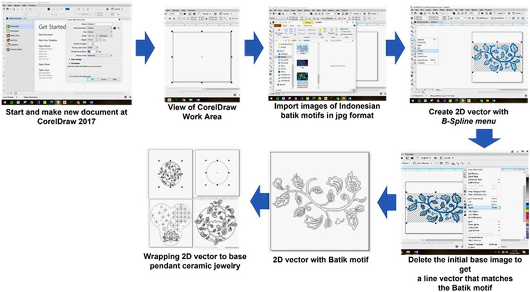
FIGURE 3. The stages of generating pendant designs and Indonesian Batik motifs in the form of a 2D model in CorelDRAW.

FIGURE 4. Stages of generating 2D CAD models into 2.5D/3D models with jewelry ceramic ornaments on Art CAM 2018.
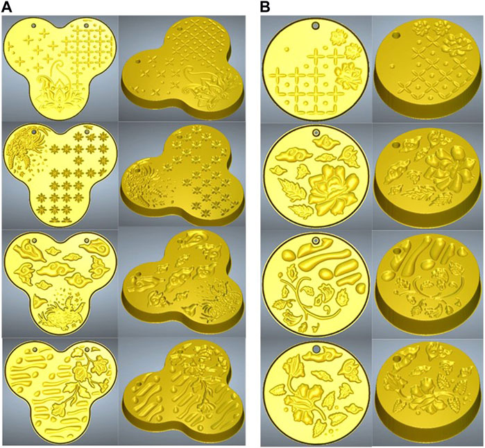
FIGURE 5. 3D CAD model of ceramic jewelry with Indonesian Batik motifs: (A) a combination of circles; (B) circle.
At this stage, it is carried out to see whether the design of the ceramic jewelry product that is being worked on is what is desired by Naruna and the customer in terms of shape, relief, ornament geometry, the distance between ornaments for cutter flexibility in Virtual Manufacturing (VM), and smoothness of relief. If the 2.5D/3D final model image built by the Art CAM Jewel engineer is according to Naruna’s wishes, then proceed to the VM stage.
At the VM stage, Autodesk Power Mill 2016 computer-aided manufacturing (CAM) software is used, which involves several activities such as making design models (perfectly completed parts), making workpieces (raw stock for machining), selecting manufacturing settings, determining machining sequences, generate toolpaths, check results, and post-process for CNC code as shown in Figures 6, 7, 8.
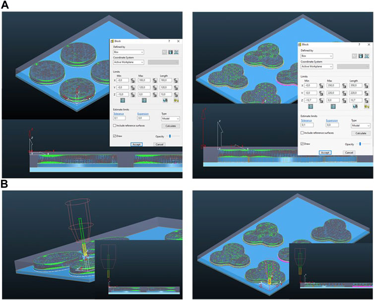
FIGURE 6. Proses set up virtual machining on CAM: (A) setting material; (B) setting cutting tools.
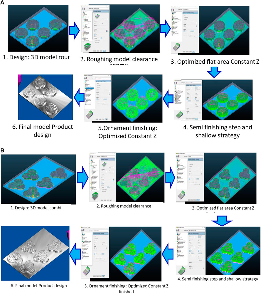
FIGURE 7. Toolpath sequence the machining process of the ceramic master model for pendant jewelry with the Indonesian Batik Combination pattern at CAM Autodesk Power Mill 2016: (A) Type of circle model; (B) circle combination type.
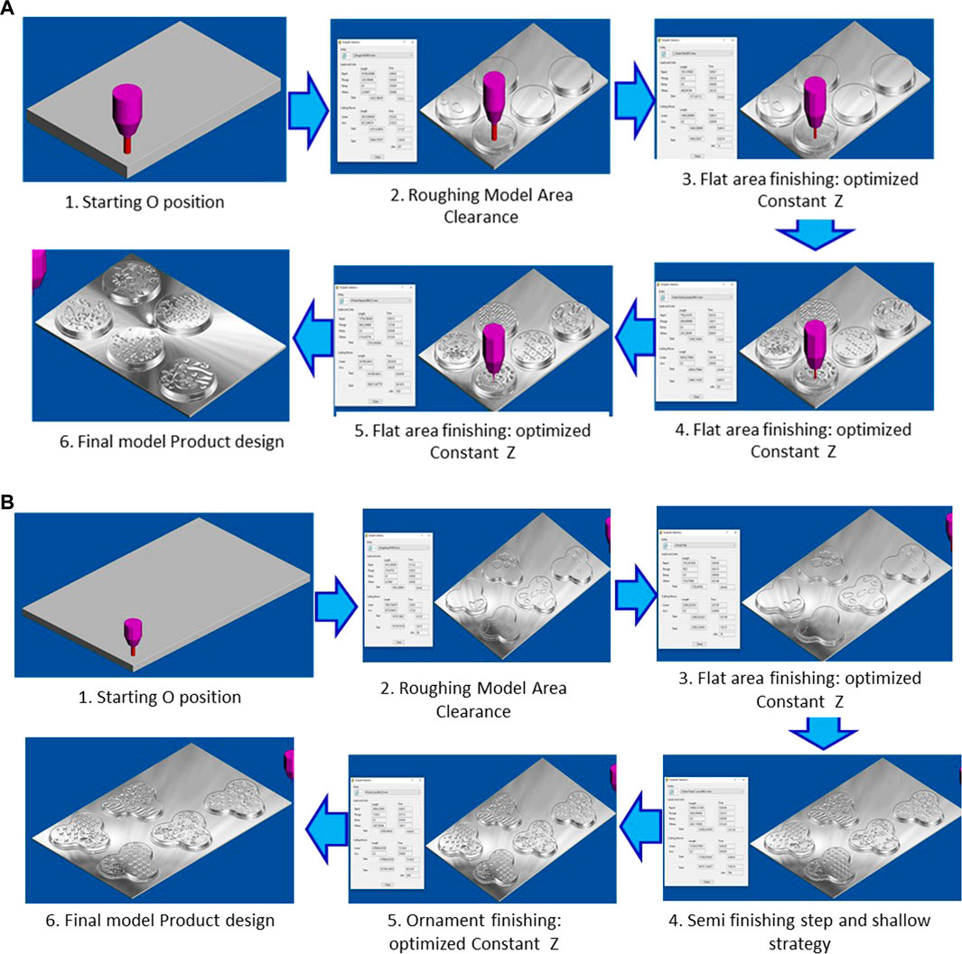
FIGURE 8. Simulation of the machining process at CAM Power Mill 2016 on the master model of a ceramic pendant jewelry with Indonesian Batik motifs at CAM Autodesk Power Mill 2016: (A) Type of circle model; (B) circle combination type.
Researchers carried out the five stages of research in this paper to obtain the best design drawings and optimize the design and manufacturing of Indonesian Batik-patterned ceramic jewelry products with VP and VM based on CAD/CAM and CNC machines. The stages of this research process can be presented in Figure 9.
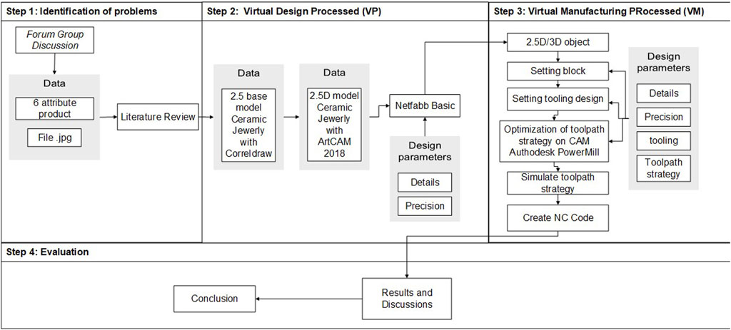
FIGURE 9. The virtual design and manufacturing stage of the artistic design of ceramic jewelry with Batik Indonesia motif.
3 Result and discussion
Ceramic art is a branch of art that processes ceramic materials. This art creates traditional and contemporary work (Renzi, 2009; Mahendri et al., 2020). Ceramics are a cover for all objects made of clay, which undergoes a heat or combustion process so that they harden. Ceramics can be made very strong, can be made to resemble heavy lead, or made as light as possible to float in water. The raw materials used to make ceramics are mostly clay and porcelain. These raw materials go through a process in such a way as to produce objects that can be used and can be displayed. In everyday life, ceramics are used as household appliances, displays, electronic devices, and building ornaments (McLaughlin, 1988a; McLaughlin, 1988b; Renzi, 2009; Zhang et al., 2018; Yao, 2017; Zhang et al., 2018; Anggoro et al., 2021; Abdullahi and Rashid, 2013; Anggoro et al., 2022; Mahendri et al., 2020).
3.1 Storytelling Indonesian batik
Batik is an image with a special drawing technique and an image in the form of an ornament. The image of Batik is usually applied to the cloth so that it has the name Batik cloth. The manufacturing process is to write night candles on a white cloth or Mori cloth using canting; then, the processing stage is processed in a certain way to produce a product commonly known as batik cloth. The word batik comes from the Javanese language, namely “mbat and tik”, which means mbat or in Indonesian, it is called throwing repeatedly, and tik is a point. So, mbatik means throwing dots on the cloth repeatedly.
The motifs in Indonesian Batik have different meanings and meanings, and this happens because of the many tribes, regions, and cultures of Indonesia. Batik artists usually get inspiration from a particular area’s surrounding conditions, nature, or history. The following is a batik motif that will be used in the design of jewelry product motifs (see Figure 10).
a. Truntum Batik motif from Yogyakarta
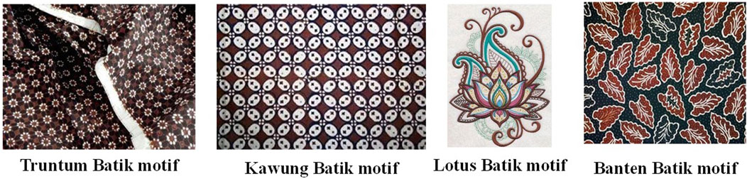
FIGURE 10. Indonesian Batik motifs selected by researchers for VP of pendant ceramic jewelry products.
The truntum batik motif from Yogyakarta is a simple batik motif and has the main ornament in the form of a sprinkling of abstract flowers of small sizes, such as jasmine flowers. Truntum batik means or becomes a symbol of unconditional love between lovers, the truntum batik motif illustrates the meaning of growing, so the cloth with the truntum batik motif is often used in Javanese traditional wedding ceremonies as clothing.
b. Kawung Batik Motif
The kawung batik motif has a pattern like kawung fruit or kolang kaling, which is geometrically drawn. Some regions say that the motif of Kawung Batik is like a picture of a lotus flower or lotus with the meaning of longevity and purity. While in general, the kawung batik motif has the meaning of a hope that can remind humans always to remember their origins. In the days of the kingdom, the kawung batik motif was only worn in royal circles.
c. Lotus Batik Motif
The lotus batik motif has a meaning as a symbol of love and life, and in the world of flora, the lotus flower is called a contemporary flower which has the meaning of purity and purity of the soul. The lotus flower is also often used in religious ceremonies and embodies the goddess Kunti in wayang (shadow puppet) stories.
d. Banten Batik Motifs
Banten batik has 75 motifs and 12 motifs that were patented in 2003. All these motifs contain a philosophy that tells Banten’s historical value, such as titles, building names, and Banten royal sites. The most famous Banten batik motif is the Nail Debus Motif.
3.2 Virtual prototyping with CorelDRAW dan art CAM 2018
The shape of the pendant is usually in the form of a flat or rectangular shape such as a square, triangle, tube, ball, circle, and so on. Naruna Ceramic Studio requested the basic design of a necklace in the form of three circles combined into one. The basic design requested is considered unique and has a simple impression but still looks magnificent. In addition, the researchers also made a pendant design with a circular base model. The researchers did this based on the results of a survey of Naruna followers who prefer the basic model of a circular necklace (Figure 11).
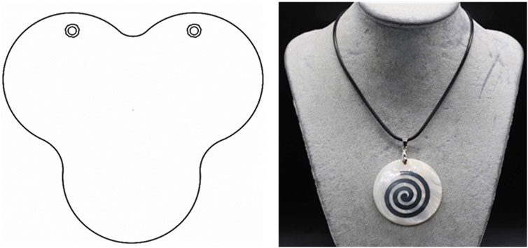
FIGURE 11. The base of the Jewelry Ceramic Pendant.
Artistic CAD engineers must do five standard stages in forming 2D vector images from input data in the form of.jpg, as previous researchers have done (Anggoro et al., 2022a; Chua…). The output obtained at this stage is a 2D image that is ready to be further processed into the art CAM software (Figure 2) and divided into two files (2D circle base pendant and circle combination pendant, see Figure 10). While the stages of vector generation from images of Indonesian Batik motifs are inserted into the pendant design (Figures 3, 4) the final result is shown in Figure 2 and Figure 5.
Through discussions between three parties in Forum Group Discussion like Sibad Engineering Company, a researcher and Naruna Ceramics Studio have agreed on motifs, shapes, and types of ceramic products that Naruna Ceramics Studio wants to develop. The data that has been obtained by researchers from the results of questionnaires and discussions led researchers to design ceramic pendant designs with Indonesian batik motifs that led to the theme of Islamic patterns. The design process is carried out using two software aids, namely CorelDraw software and Art Cam software (Figures 3, 4). Previous researchers also carried out this stage and were successfully carried out in the local ceramic industry in Indonesia (Fergiawan et al., 2019; Mahendri et al., 2020; Anggoro et al., 2021 Anggoro et al., 2022; Yuniarto et al., 2022). In this study, researchers have made ten pendant designs with two different basic models, namely five pendant designs with a basic shape of three circles as requested by Naruna Ceramics Studio and five other pendant designs in the form of a circle obtained from the questionnaire results (Figures 5, 10). The ten designs have Indonesian batik motifs by combining classic Batik with modern Batik. Researchers use three classical batik motifs: the kawung batik motif, the machete batik motif, and the mega mendung batik motif (Figure 5). The three motifs were chosen because, from the results of the discussion, these motifs were considered the most popular or that many people know as the hallmark of Batik, while for modern batik motifs, flora motifs, namely leaves and flowers, were chosen to make the pendant design sweeter and more feminine (Clayton, 1986; Renzi, 2009; Abdullahi and Rashid, 2013; Abdullahi and Rashid, 2015; Anggoro et al., 2022; Mahendri et al., 2020).
Two basic pendant designs have a thickness of 0.50 cm with a hole size of 0.30 cm and lengths and widths of different sizes. In the basic form, three circles are 9.00 cm × 9.00 cm. The pendant is designed in the form of a circle, and it has a diameter of 5.00 cm. All ornaments contained in the pendant designs are made with a deboss type, which has a depth of 0.10 cm, and the distance between ornaments in all pendant designs is made with a size of 0.10 cm. Size details can be seen in Figure 11. These sizes are given by considering the smallest cutter size on the CNC machine owned by CV. Sibad Engineering is 0.10 cm in size. If the size is less than 0.10 cm, then the pendant design ornaments cannot be seen clearly (Figure 11). This milling cutter is often known as a ball nose type milling cutter which CNC operators use in the finishing process to obtain a smooth, precise, and accurate surface quality of ceramic products (jewelry ceramics) according to visualization in virtual design and manufacturing as well as at the realization stage on CNC machines. The size details of these ten Indonesian Batik-patterned ceramic jewelry designs can be presented in Figure 12, which can be imported directly for the Virtual Machining process with Autodesk Power Mill 2019i software.
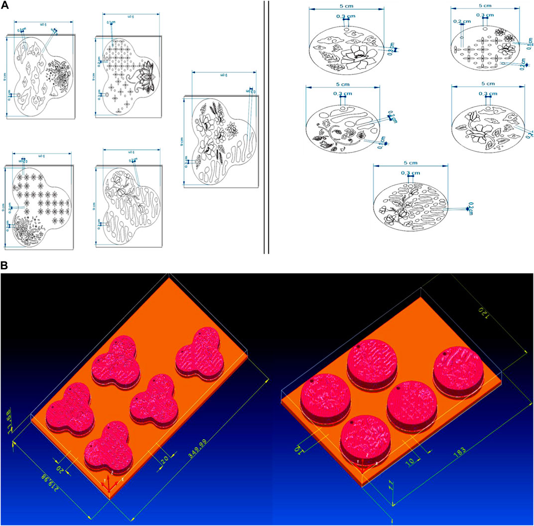
FIGURE 12. Size details of Indonesian Batik patterned pendants: (A) 2D vector model; (B) 3D model at Virtual Design with Autodesk Power SHAPE 2019i.
3.3 Virtual machining with autodesk powermill 2019
3.3.1 Setting the placement of the 3D CAD ceramic model for Indonesian batik jewelry
3D models of five ceramic pendants with motifs of Batik Indonesia Combination according to a design that the Engineer Team has mutually agreed upon and Naruna are placed simultaneously and aligned in two rows of square blocks according to the position of the CNC router machine table (Figure 12). Furthermore, these two models were set up for model placement through virtual design and machining using CAD and CAM software as has been done by previous researchers (Clayton, 1986; Homer and Skaar, 1991; Yao, 2017; Zhang et al., 2018; Fergiawan et al., 2019; Fergiawan et al., 2021; Anggoro et al., 2022). The material block sizes prepared in CAD are 183 × 120 × 11 mm and 350 × 220 × 11.68 mm (see Figure 12B). The ceramic pendant model is placed in two rows and two columns, as in Figure 12B. The distance between the pendant models in this paper is set at 10 mm to facilitate handling for cutting by the mold operator in the fabrication department at Naruna. Each circle-type pendant has a diameter of 50 mm and a thickness of 5.5 mm, while the other types adapt to the initial design. The position block is placed at the top of half the thickness of the material block. After machining at the CNC router, the rest of the block is planned to have a thickness of 3 mm so that the gypsum plaster block is not quickly broken when lifted from the machine table. Homer & Skaar, (1991) have also done this, (McLaughlin, 1988a; Zhang et al., 2018; Fergiawan et al., 2019; Mahendri et al., 2020; Yuniarto, et al., 2022).
3.3.2 Virtual machining program creation
Making machining process programs using Autodesk Power Mill software version 2016. This software supports CAM machining programs that generate NC codes to be executed using a CNC Machine. In this paper, it will be done using a CNC router machine. Before the NC code is executed, the CAM program that has been created can be monitored by running a virtual simulation process to see the complete feed of the overall surface geometry and the amount of time it takes to complete the machining process. This has also been proven and successfully carried out by previous researchers (Chang, 2015b; Chang, 2015c; Oancea, 2013; Mircheski et al., 2019; Vardhan and Sridhar Babu, 2020; Fergiawan et al., 2021; Anggoro et al., 2021; Anggoro et al., 2022). In PowerMill, there is a choice of machining process strategies from 3 axes to 5 axes, but in this case, it adjusts to the availability of CNC machines that only work on three axes. The CAM process for 3D model machining Ceramic pendants with motifs combining Indonesian Batik is displayed in a virtual simulation using PowerMill.
3.3.3 Material settings
The material blocks prepared are in the form of blocks according to the block model with an area of 183 × 120 mm and 350 × 220 mm. However, for the height size, 2 mm was added to level the surface before the pendulum model cutting process was carried out. So that the material block dimensions 183 × 120 × 13 mm must be prepared (Figure 5B; Figure 6) and 350 × 220 × 13.70 mm (Figure 5A; Figure 6). The x-axis is directed at the longitudinal position of 183 mm and 350 mm, the y-axis is for the width of 120 mm and 220 mm, while the Z-axis is directed at the vertical position for 13 mm and 13.70 mm. The type of block material that will be used is plaster mold.
3.3.4 Setting cutting tools
Cutting tools prepared for the machining process are carbide coating with endmill flute diameters of 6 mm and 3 mm and Ball nose of 2 mm and 0.5 mm. The spindle rotation is set at 5,000 rpm for plaster mold material with a feed rate of 300 mm/min. The maximum cutting tool movement height is 10 mm above the workpiece surface and starts rotating at 5 mm above the workpiece surface. The start point is above the work axis at a height of 15 mm; at the end of the process, it stops on the work plane at a height of 20 mm (Figure 6).
3.3.5 Roughing the entire surface
The entire surface roughing process uses the Model Area Clearance strategy with an offset pattern of All, i.e., feeding starts from the top centre of the surface, and then the cutting tool moves little by little to make a pattern out around the surface to the edges. This roughing strategy was chosen because the initial material is in the form of blocks, and the length and width exceed the block size specified above. This is done because the block material must be gripped at the edge on the work table so that there must be an offset outer area for the workpiece gripping area. So later, the finished product will be formed in a pocket block of material.
This strategy uses the Endmill cutting tool with a flute diameter of 6 mm with a stepover of 4.5 mm (75% flute diameter), and a stepdown of 1 mm. This roughing process leaves a surface thickness of 0.3 mm for the next process (Figures 7, 8). The time required to complete this process is 1 h 42 min 0 s for the circle pendant type (Figure 5B) and 5 h 33 min 15 s for the circle combination type pendant (Figure 5A).
3.3.6 The process of finishing the flat area of the block base
The process of finishing the base area of the block uses the Optimized Constant Z finishing strategy. This strategy works very well on flat surfaces with no difference in elevation levels, although it is a good strategy for contoured surfaces with constant stepdown contour descent. However, on a completely flat surface, this constant z-level groove is utilized to level a flat surface completely. In addition, feeding with a constant decrease in z level is also used to reduce the surface of the pendulum circle model’s edge wall.
This strategy uses an Endmill cutting tool with a 3 mm flute diameter with a 1.2 mm stepover (40% flute diameter) directly consuming a surface thickness of 0.3 mm. This process took 52 16 s (Figure 5B) and 1 h 1 min 51 s (Figure 5A).
3.3.7 Five pendant semi finishing process
The next process is to finish the surface area of the pendulum, which is quite intricately ornate. It must be done carefully. A small cutting tool is needed to get a detailed ornament, a 0.5 mm ball nose. However, the food residue from the previous cutting tool, the Endmill measuring 6 mm flute diameter, which will be processed with a 0.5 mm cutting tool, will be quite heavy for the cutting tool. So that, an intermediate process is needed, namely the semi-finishing process using a Ball nose-cutting tool with a flute diameter of 2 mm.
The machining process strategy in this semi-finishing process is the Steep and Shallow finishing strategy using the Ball nose cutting tool with a flute diameter of 2 mm. The spindle rotation is 5,000 rpm with a 250 mm/min feed speed. This strategy is almost the same as the Optimized Constant-Z finishing strategy, only with a different stepdown that can be set. It is used on sloping contoured surfaces, especially with extreme slopes and vertical walls. With a step-down setting that is smaller than the stepover, the potential for surface flatness can be maintained. This process uses a stepover of 0.7 mm (30% flute diameter) and a stepdown of 0.3 mm and leaves a thickness of 0.1 mm for the finishing process. The time required to complete this process is 4 h 39 min 15 s (Figure 5B) and 7 h 40 min 18 s (Figure 5A).
3.3.8 Five pendant finishing process
The last machining process is feeding the ornament area with detail. The toolpath strategy used is Optimized Constant Z Finishing using a 0.5 mm flute diameter ball nose cutting tool. This strategy is needed for surface feeding with a constant stepover and step-down to get a good surface contour. This process uses a step-down of 0.05 mm (10% of the flute diameter). The spindle rotation is still 5,000 rpm, but the feed rate is reduced to 200 mm/min to reduce the risk of force on small-diameter cutting tools. This process took 36 h 14 min 55 s (Figure 5B) and 84 h 12 min 56 s for Figure 5A.
The results of all virtual machining processes from both ceramic models of pendant jewelry with the Indonesian Batik Combination pattern have also been proven effective and successfully carried out by previous researchers on CNC machines [Clayton, 1986; McLaughlin, 1988b; Oancea, 2013; Chang, 2015c; Vardhan and Sridhar Babu, 2020; Ratnanta et al., 2020; Fergiawan et al., 2021; Anggoro et al., 2021; Anggoro, et al., 2022; Bawono et al., 2019; Yuniarto et al., 2022] with maximum results and Naruna has traded some. This research discusses the virtual machining stage in the Power Mill CAM software because the NC Code results can be directly executed on a CNC router machine that uses a Mach3 post processor or is compatible with Power MILL. The final results of the virtual machining time of the two models can be presented in Table 1. These results can be realized well if the NC Code output we produce in this paper can run on a CNC router machine according to the machining parameters set in Table 1. Previous researchers have also used this parameter well (Ullman, D. G., 1992;Yao, 2017; Zhang et al., 2018; Fergiawan et al., 2021; Yuniarto et al., 2022). The final result of the machining process for both types of pendant jewelry designs (Figure 5) can be presented in Figure 13 and manufactured using a CNC router machine. The master material for the jewelry model used is white gypsum. It can be seen that the details of the relief contours and ornaments that are formed on the pendant’s surface match the IBM model developed in this study. This master jewelry product can then be further processed for fabrication in the local ceramic industry in Indonesia, such as PT Nuanza Porcelain Indonesia and Naruna Ceramic Studio.
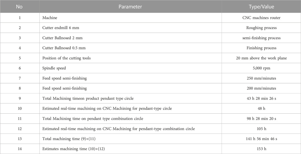
TABLE 1. Optimal parameters of Indonesian batik-patterned ceramic jewelry for circle type and circle combination type.
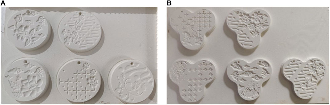
FIGURE 13. Master model jewelry pendant with combination Batik Indonesian Motifs: (A) type one circle; (B) type three circle combination.
4 Conclusion
Virtual machining and design proved once again very effective and contributed greatly to design engineers and the patterned porcelain ceramic industry like Naruna to develop precise, accurate, and fast designs for ceramic jewelry products with Indonesian Batik patterns. The results of the design and optimization of the machining toolpath strategy obtained in this paper can be directly applied by the ceramic industry to ceramic pendant jewelry products with Indonesian batik motifs.
Appropriate and sustainable use of virtual machining technology in this paper can also show design and manufacturing engineers to be more confident and competent in implementing virtual machining simulation tools to overcome the manufacturing capabilities of commercial and industrial products. It is also to get a reasonable estimate of machining time in the design and manufacture of custom ceramic jewelry products that are according to customer demand and can face industrial competition in the industrial era 4.0.
This study resulted in optimal parameter settings, namely: Machine CNC router, Cutter endmill 6 mm for Roughing process, Cutter Ballnosed 2 mm for semi-finishing, Cutter Ballnosed 0.5 mm for the Finishing process, Spindle speed 5,000 rpm, Feed speed semi-finishing 250 mm/minutes, Feed speed semi-finishing 200 mm/minutes, Machining time pendant 43 h 28 min 26 s and machining time Circle 98 h 28 min 20 s, so total machining time at 141 h 56 min 46 s. Estimates machining time at 48 + 105 = 153 h. So finally, the total time saving is about 11 h. This research also has obtained Accurate prediction time to design with several masters of ceramic jewelry pendant products with a combination of Indonesian batik motifs, which can be continued in the fabrication of the local ceramic industry in Indonesia.
In future research, we will provide a more in-depth and comprehensive understanding of the primary fabrication process for this jewelry ceramic mold pattern with different models and product types.
Data availability statement
The original contributions presented in the study are included in the article/supplementary material, further inquiries can be directed to the corresponding author.
Author contributions
BB: Conceptualization, Investigation, Validation, Writing–review and editing, Resources, Visualization. TY: Methodology, Validation, Writing–review and editing, Data curation, Formal Analysis, Resources, Visualization. PA: Formal Analysis, Funding acquisition, Investigation, Resources, Software, Writing–review and editing, Methodology, Supervision. CS: Conceptualization, Investigation, Writing–original draft, Data curation. SF: Project administration, Resources, Visualization, Writing–review and editing. OW: Project administration, Resources, Writing–review and editing.
Funding
The author(s) declare financial support was received for the research, authorship, and/or publication of this article. This work was supported and funded by the Directorate of Research and Community Service, Directorate General of Research and Development Strengthening, Ministry of Research, Technology and Higher Education Fiscal Year 2022, Grant Number: 157/E5/PG.02.00.PT/2022 (30 Mei 2022) dan 1989.4/LL5-INT/PG.02.00/2022/168/LPPM-Pen/Eks.
Acknowledgments
We want to thank the Directorate of Research and Community Service, Directorate General of Research and Development Strengthening, Ministry of Research, Technology and Higher Education Insdonesia, LPPM UAJY, PT Gyan Kreatif Indonesia and Naruna Ceramic Studio so that this paper can be completed properly.
Conflict of interest
The authors declare that the research was conducted in the absence of any commercial or financial relationships that could be construed as a potential conflict of interest.
Publisher’s note
All claims expressed in this article are solely those of the authors and do not necessarily represent those of their affiliated organizations, or those of the publisher, the editors and the reviewers. Any product that may be evaluated in this article, or claim that may be made by its manufacturer, is not guaranteed or endorsed by the publisher.
References
Abdullahi, Y., and Rashid, M. (2013). Evolution of ISLAMIC geometric patterns. Front. Archit. Res. 2 (2), 243–251. doi:10.1016/j.foar.2013.03.002
Abdullahi, Y., and Rashid, M. (2015). Evolution of abstract vegetal ornaments in Islamic architecture. Archnet- IJAR 9 (1), 31–49. doi:10.26687/archnet-ijar.v9i1.558
Adhikary, N., and Gurumoorthy, B. (2018). A slice-based algorithm for automatic and feature-preserving hole-filling in a CAD mesh model. Computer-Aided Des. Appl. 15 (6), 780–795. doi:10.1080/16864360.2018.1466807
Anggoro, P. W., Tan Wijaya, A. R., Yuniarto, T., Bayuseno, A. P., Jamari, J., Bayuseno, A. P., et al. (2021). Reverse engineering from 3D mesh to ceramic product in the form of Miranda Kerr tea for one teapot in PT Doulton Indonesia. Cogent Eng. 8 (1), 1–20. doi:10.1080/23311916.2021.1981522
Anggoro, P. W., Yuniarto, T., Bawono, B., Felasari, S., Setyohadi, D. B., Widyanarka, O. K. W., et al. (2022). Advanced design and fabrication of islamic tile ceramic wall tiles with Indonesian batik patterns using artistic CAD/CAM and 3D printing technology. Front. Mech. Eng. 7, 799086. doi:10.3389/fmech.2021.799086
Bawono, B., Anggoro, P. W., Tauviqirrahman, M., Jamari, J., Bayuseno, A. P., and Antony, A. A. (2019). Optimization parameters tooling design to increase the surface quality of orthotic insole shoes using the taguchi approach and surface response methods. Mater. Today Proc. 13, 47–52. doi:10.1016/j.matpr.2019.03.185
Chang, K. H. (2015a). Introduction to e-Design. Des. theory methods using CAD/ CAE. Computer-Aided Eng. Des. Ser. 2015, 1–37. doi:10.1016/B978-0-12-398512-5.00001-3
Chang, K. H. (2015b). Geometric modeling. Des. theory methods using CAD/CAE. Computer-Aided Eng. Des. Ser. 2015, 41–124. doi:10.1016/B978-0-12-382038-9.00002-8
Chang, K. H. (2015c). Virtual machining. Computer-Aided Eng. Des. Ser. 2015, 599–646. doi:10.1016/B978-0-12-382038-9.00011-9
Clayton, C. G. A. (1986). The use of CAD/CAM for the design and manufacture of moulds for ceramic products. Ceram. Forum Int. 63 (4/5), 216–221.
Cross, N. (2005). Engineering design methods: strategy for product design. 3th ed. England: Jhon Wiley and Sons, Ltd.
Darmanto, D., Novriansyah, R., Ismail, R., Jamari, J., Anggoro, P. W., and Bayuseno, A. P. (2022). Reconstruction of the artificial knee joint using a reverse engineering approach based on computer aided design. J. Med. Eng. Technol. 46 (2), 136–147. doi:10.1080/03091902.2022.2026502
Eide, A. R., Mickelson, S., Jenison, R., and Northup, L. L. (2012). Engineering fundamentals and problem solving. 6th ed. USA: McGraw-Hill.
Fergiawan, P. K., Anggoro, P. W., Anthony, A. A., Tauviqirrahman, M., Jamari, J., and Bayuseno, A. P. (2021). Simulation of manufacturing strategy of an orthotic boots shoe insole product with computer-aided manufacturing for club foot patient. IOP Conf. Ser. Mater. Sci. Eng. 1034, 12095. doi:10.1088/1757-899X/1034/1/012095
Fergiawan, P. K., Anggoro, P. W., Yuniarto, T., Purwanto, K. B., and Widyanarka, O. K. W. (2019). “Ceramic jewelry with texture and ornament Islamic pattern and Batik Indonesia – design, manufacturing, and fabrication,” in Proceeding of 6th international conference and exhibition on sustainable energy and advanced materials, lecture note in mechanical engineering (Surakarta, Indonesia: Springer). ICE-SEAM, 16-17 October 2019.
Homer, P., and Skaar, E. C. (1991). Computer usage in the ceramic industry: a CERABULL review. Ceram. Bull. 70 (2), 198–199.
Mahendri, C. D., Anggoro, P. W., Fergiawan, P. K., Yuniarto, T., Bayuseno, A. P., and Jamari, J. (2020). Development of the ceramic Jewellery industry for necklace with Indonesian batik motifs. Proceedings of the 2nd borobudur international symposium on science and technology (BIS-STE 2020). Adv. Eng. Res. 203, 387–393. doi:10.2991/aer.k.210810.067
McLaughlin, P. (1988a). Observations on the use of computers in the ceramic industries (Part 1). Br. Ceram. Trans. J. 87 (4), 113–l16.
McLaughlin, P. (1988b). Observations on the use of computers in the ceramic industries (Part 2). Br. Ceram. Trans. J. 87 (5), 146&14X.
Mircheski, I., Lukaszewicz, A., and Szezebiot, R. (2019). Injection process design for manufacturing of bicycle plastic bottle holder using CAx tools. Procedia Manuf. 32, 68–73. doi:10.1016/j.promfg.2019.02.184
Oancea, G., Ivan, N. V., and Pescaru, R. (2013). “Computer-aided reverse engineering system used for customized products,” in Annals of MTeM for 2013 and Proceedings of the 11th International MTeM Conference, 181–186.
Pradhan, S., Ranjan Das, S., and Dhupal, D. (2021). Performance evaluation of recently developed new process HAJM during machining hardstone quartz using hot silicon carbide abrasives: an experimental investigation and sustainability assessment. Silicon 13, 2895–2919. doi:10.1007/s12633-020-00641-9
Ratnanta, S. W., Anggoro, P. W., Fergiawan, P. K., Jamari, J., and Bayuseno, A. P. (2020). Optimization of the toolpath strategy for the master ceramic jewelry mold pattern using the Rhinoceros software and router CNC machine. Proceedings of the 2nd borobudur international symposium on science and technology (BIS-STE 2020). Adv. Eng. Res. 203, 381–396. doi:10.2991/aer.k.210810.066
Renzi, J. (2009). The art of tile: designing with time-honored and new tiles first. Potter Style 10, 0307406911.
Saxena, P., Bissacco, G., Meinert, K. A., and Bedka, F. J. (2020). Mold design and fabrication for production of thermoformed paper-based packaging products. J. Manuf. Process. 58, 311–321. doi:10.1016/j.jmapro.2020.07.029
Vardhan, T. V., and Sridhar Babu, B. (2020). Multiaxis CNC programming and machining. Mod. Manuf. Process. Woodhead Publ. Rev. Mech. Eng. Ser. 2020, 167–175. doi:10.1016/B978-0-12-819496-6.00009-9
Yao, J. G. (2017). “Application of Computer-Aided Design in ceramic art design,” in International Conference on Manufacturing Construction and Energy Engineering (MCEE 2017), August 17-18, 2017, 252–256.
Yuniarto, T., Anggoro, P. W., Bawono, B., Fergiawan, P. K., Bayuseno, A. P., and Jamari, J. (2022). “Development of the ceramic Jewellery industry in the form of necklaces with Indonesian batik motifs,” in Proceedings of 7th International Conference on Industrial, Mechanical, Electrical and Chemical Engineering 2021 (ICIMECE 2021), Surakarta, Indonesia, 5 October 2021. AIP Proceeding. Accepted for publication.
Keywords: batik, jewelry ceramic, creative method, art CAM, power mill
Citation: Bawono B, Yuniarto T, Sanusi CEP, Felasari S, Widyanarka OKW and Anggoro PW (2024) Optimization of virtual design and machining time of the mold master ceramic jewelry products with Indonesian batik motifs. Front. Mech. Eng 9:1276063. doi: 10.3389/fmech.2023.1276063
Received: 11 August 2023; Accepted: 05 December 2023;
Published: 04 January 2024.
Edited by:
David Romero, Monterrey Institute of Technology and Higher Education (ITESM), MexicoReviewed by:
Md Irfanul Haque Siddiqui, King Saud University, Saudi ArabiaElif Eren Gültekin, Selçuk University, Türkiye
Copyright © 2024 Bawono, Yuniarto, Sanusi, Felasari, Widyanarka and Anggoro. This is an open-access article distributed under the terms of the Creative Commons Attribution License (CC BY). The use, distribution or reproduction in other forums is permitted, provided the original author(s) and the copyright owner(s) are credited and that the original publication in this journal is cited, in accordance with accepted academic practice. No use, distribution or reproduction is permitted which does not comply with these terms.
*Correspondence: B. Bawono, YmFqdS5iYXdvbm9AdWFqeS5hYy5pZA==