 Jianzhi Wang
 Hang Xiao
 Xilun Ding
 Shengnan Lyu
- Robotics Institute, School of Mechanical Engineering and Automation, Beihang University, Beijing, China
A spatial deployable mechanism is capable of adapting to different operating requirements by adjusting its shape and size. However, most current deployable mechanisms fail to maintain the type of their reflective surface during the folding process, which limits their ability to adjust the optimal operating frequency. To address this issue, this paper presents a novel design of a deployable mechanism with a type-preserving feature inspired by kirigami techniques. By preserving the type of its reflective surface, this mechanism allows for the adjustment of the optimum operating frequency according to specific requirements. This makes it well-suited for deployment on commercial satellites that undergo constant mission variations. The mechanism is constructed using porous kirigami cells, ensuring that the type of the working surface is maintained throughout the deployment process. The construction of deployable units and networks based on porous cells is also discussed. Additionally, deployable mechanisms with controllable Poisson’s ratios are developed. The kinematics of the mechanism are analyzed to verify the type-preserving characteristics. Finally, four case studies are conducted to illustrate and validate the proposed design and analysis.
1 Introduction
A deployable mechanism can be compactly folded into a small size for easy transportation and expanded to a large structure at working conditions, meaning they have been widely utilized in different applications (Ding et al., 2020; Shi Chuang et al., 2021; Lim et al., 2022). Many studies on deployable mechanisms have been conducted in recent years. Ramadoss et al. summarized a family of deployable mechanisms that approximated a series of curves and surfaces using the polygonal approximation technique (Ramadoss et al., 2019). Xu et al. designed and analyzed a truss deployable antenna mechanism based on a 3UU-3URU unit (Xu et al., 2019). Duan provided a survey of research activities of Large spaceborne deployable antennas (LSDAs) in the past, present, and future (Duan, 2020). Dai and Xiao designed a new deployable truss structure for large caliber antennas (Dai and Xiao, 2020).Shi et al. proposed a new type of cable-strut antenna mechanism; optimization of the mechanism synthesis was established (Shi C. et al., 2021). Most researchers focus on the folded and deployed states of deployable mechanism while ignoring the intermediate configuration. The deployable mechanism will be sufficiently utilized if the intermediate state can maintain a type similar to that of the deployed state.
Kirigami is a combination of paper cutting and folding. It can obtain a three-dimensional structure with a certain functional type from a compact storage (flat) configuration. Kirigami can effectively provide new ideas and solutions for the design of deployable mechanisms. Saito et al. proposed a novel method to construct arbitrary cross-section composite honeycombs by changing the crease and cut pattern (Nojima and Saito, 2006; Saito et al., 2014). Broccolo et al. described the development, manufacturing, and testing of a zero Poisson’s ratio cellular structure using kirigami-inspired techniques (Broccolo et al., 2017). Calisch et al. designed an algorithm for producing a processable cut-and-fold pattern from a three-dimensional volume (Calisch et al., 2018). Neville et al. presented a shape memory polymer honeycomb with tunable and shape-morphing mechanical characteristics (Neville et al., 2017). Lyu et al. developed a novel family of cellular mechanical metamaterials based on rigid-foldable square-twist origami (Lyu et al., 2021).
Inspired by the porous unit structure in kirigami, a novel deployable mechanism with a type-preserving feature is proposed in this paper. A parabolic cylindrical surface can be approximated not only at the fully deployed state but also at the intermediate state. Different Poisson’s ratios of the mechanism can be realized by the design of a unit combination scheme.
In the following section, the introduction of the type-preserving feature is described. In Section 3, the typical basic cells and units are presented; the construction of networks is undertaken to obtain different Poisson’s ratios. Two geometric methods are proposed to obtain the parameters to approximate cylindrical surface. One method is specifically designed to approximate a parabolic cylindrical surface, while the other is suitable for approximate arbitrary cylindrical surface. In Section 4, position analysis is performed and the type-preserving feature is proved. Three cases with different Poisson’s ratios are performed and validated by simulations in Section 5.
2 Type-preserving feature
Figure 1 presents the three different configurations of a typical deployable mechanism, namely the folded, intermediate, and deployed configurations (Xiao et al., 2018). It can be easily transported and stored at the folded state. The mechanism in the fully deployed configuration can fit a cylindrical surface, which is usually utilized as the reflector of an antenna. Little attention had been paid to the intermediate configuration of the mechanism, since there is hardly any practical application value with its irregular outer contour.
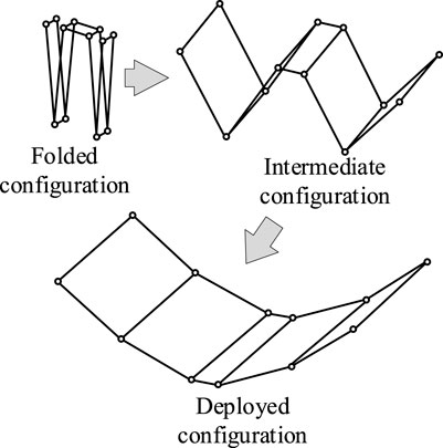
FIGURE 1. Configurations of a deployable mechanism.
To fully use the deployable mechanism, it is desired that the mechanism in the intermediate configuration can have a working surface. A novel kirigami-inspired deployable mechanism, which has the feature of type preserving, is proposed in this paper. Herein, type preserving indicates that the fitted surfaces in the intermediate and deployed configurations are of the same type, for example both are parabolic cylindrical surfaces. Parameters of the fitting surface may change while the type of the surface remains the same.
An example of the proposed mechanism is shown in Figure 2. From the side view, it can be found that the mechanism can approximate cylindrical surfaces whose directrix is a biquadratic curve. With the changing of deployable angles, coefficients of the directrix varies but the type of the curve is invariable.
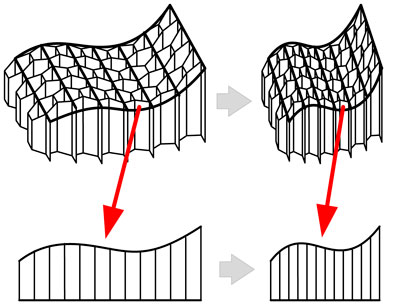
FIGURE 2. An example of a kirigami-inspired type-preserving mechanism.
3 Construction of the deployable mechanism
The designed deployable mechanism is inspired by kirigami, which integrates both folding and cutting. The mechanism can be constructed from a flat sheet with creases and cuts. Three typical cells are selected for forming the basic units with different Poisson’s ratios. Type-preserving networks based on the units are established to approximate parabolic cylindrical surfaces.
3.1 Basic cells
Three typical basic cells, namely the hexagonal cell, the re-entrant hexagonal cell, and the semi re-entrant hexagonal cell, are adopted in the design of a type-preserving deployable mechanism in this study (Grima et al., 2010; Li et al., 2021). The cross-sections of the basic cells are illustrated in Figure 3.
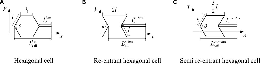
FIGURE 3. Cross-sections of typical basic cells (A) Hexagonal cell (B) Re-entrant hexagonal cell (C) Semi re-entrant hexagonal cell.
During their movement, the three sets of opposite sides remain parallel; the only variable is the deployable angle θ shown in Figure 3. Lengths along the horizontal direction of the hexagonal cell, re-entrant hexagonal cell, and semi re-entrant hexagonal cell are denoted as
where l1 is the length of the sloping edge of the hexagonal cell, while
The Poisson’s ratio of cells is defined as
Then for three different cells, the Poisson’s ratio can be calculated as
Here, if θ∈ [60°, 160°], then the variation of Poisson’s ratio of cells with respect to the deployable angle θ is shown in Figure 4.
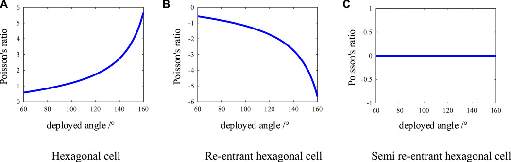
FIGURE 4. The variation of Poisson’s ratio of cells with respect to the deployable angle (A) Hexagonal cell (B) Re-entrant hexagonal cell (C) Semi re-entrant hexagonal cell.
As shown in Figure 4, the hexagonal cell exhibits a positive Poisson’s ratio, the re-entrant hexagonal cell displays a negative Poisson’s ratio, and the semi re-entrant hexagonal cell has a zero Poisson’s ratio. The distinct structural styles of these three basic cells lead to variations in their respective Poisson’s ratios.
In the proposed design, the cells are 3D honeycomb structures. Kirigami is considered as an innovative and effective method for advanced three-dimensional fabrication through cutting and folding thin sheets. Inspired by kirigami, a novel single-layer-folding method is proposed to obtain the 3D cell from flat paper. The crease and cut patterns of the three basic cells are shown in Figure 5. The structural parameters are illustrated in the figure. The solid and dotted lines represent the mount and valley creases, respectively. The sheet is cut along the bold lines.
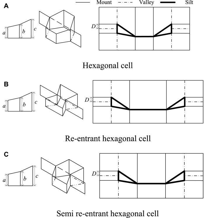
FIGURE 5. The crease and cut patterns of the three basic cells (A) Hexagonal cell (B) Re-entrant hexagonal cell (C) Semi re-entrant hexagonal cell.
According to the geometric constraints, parameters a, b, c, and D of the cells satisfy the following conditions
The folding process of the hexagonal cell is shown in Figure 6. It is similar to the folding process of the re-entrant hexagonal cell and the semi re-entrant hexagonal cell.

FIGURE 6. The folding process of hexagonal cell.
There is no need to stick the sheet using the single-layer-folding method, which makes it easy to obtain the deployable mechanism from a flat sheet. The proposed single-layer-folding method is suitable for small curvature directrix and sheets with a certain thickness.
3.2 Units with different Poisson’s ratios
By combining the basic cells, three basic units with different Poisson’s ratios are obtained. The unit with a positive Poisson’s ratio is obtained by combining three hexagonal cells. Three re-entrant hexagonal cells are connected to get a negative Poisson’s ratio unit. The zero Poisson’s ratio unit is obtained by arranging the three basic cells, which is named the integrated unit. The three basic units, the corresponding crease, and the cut patterns are shown in Figure 7. The left side of Figure 7 shows the top view of the three basic units. Black lines indicate that the unit is in the fully deployed configuration; the intermediate configuration of the unit is shown in red. The front view and axonometric view are shown in the middle. The crease and cut pattern of the three basic units is on the right side of Figure 7.
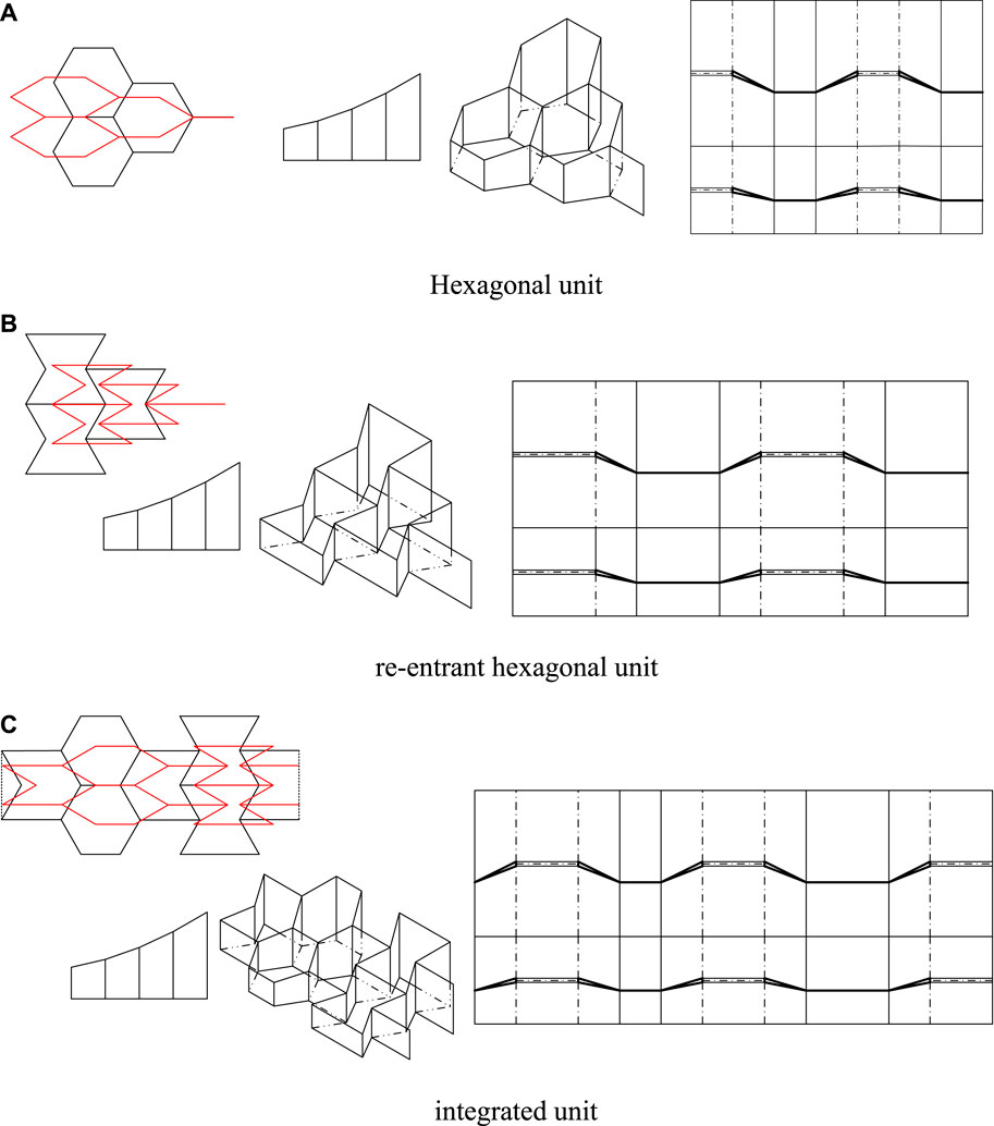
FIGURE 7. Three basic units (A) Hexagonal unit (B) re-entrant hexagonal unit (C) integrated unit.
3.3 Network of the basic units
The size of a unit is limited. Thus, the large-scale deployable mechanism should be constructed by networking the proposed units. Different deployable mechanisms with positive, negative, and zero Poisson’s ratios are constructed with the three kinds of units.
It is assumed that the mechanism is in its fully deployed configuration when the deployable angle θ is 120°. As shown in Figure 8A, in the first network, three hexagonal units with the same size but different colors are patterned along the horizontal and vertical directions. The Poisson’s ratio of the mechanism is positive. Similarly, a mechanism with negative Poisson’s ratio is obtained by networking the re-entrant hexagonal units, as shown in Figure 8B.
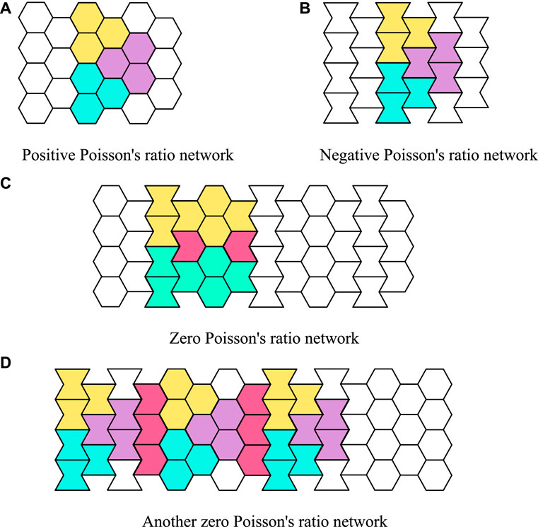
FIGURE 8. Network of the basic units (A) Positive Poisson’s ratio network (B) Negative Poisson’s ratio network (C) Zero Poisson’s ratio network (D) Another zero Poisson’s ratio network.
Two networking patterns are presented in Figures 8C, D to obtain mechanisms with zero Poisson’s ratio. Figure 8C shows the tessellation of the integrated units; two magenta semi re-entrant hexagonal cells need to be added between two integrated units. Since the Poisson’s ratio of this unit is zero, the composed mechanism is zero Poisson’s ratio accordingly. In Figure 8D, hexagonal units and re-entrant hexagonal units are patterned with the semi re-entrant hexagonal cells. Some parts of the mechanism are positive Poisson’s ratio and other parts are negative Poisson’s ratio. The Poisson’s ratio of the whole mechanism is zero.
3.4 Geometric methods for approximating cylindrical surfaces
3.4.1 Approximating parabolic cylindrical surface
Parabola has the advantage of gathering signals to its focus, and is widely used in antenna reflectors (Xiao et al., 2020). Based on the proposed deployable mechanism, continuous tangents are selected to fit the directrix of the parabolic cylindrical surface, as shown in Figure 9. The points of tangent are exactly located on the parabola.
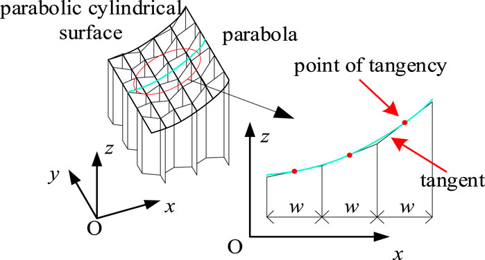
FIGURE 9. Approximation of parabolic cylindrical surface.
The continuous tangents are the projection of the upper surface of each unit on the plumb surface. The horizontal length of the fitted tangent is the width of the projection of its corresponding unit on the plumb surface, which is denoted as w. Therefore, the x-coordinate of the first fitting point is w/2.
According to the geometric relationship between the tangent and parabola, the tangent slope k can be deduced as
where g is the parabola coefficient and xt represents the x-coordinate of the fitting point.
The intercept e of the tangent is
where yt is the y-coordinate of the tangent point.
For a given parabola with the coefficient g, the expression of the tangent corresponding to the first fitting point can be obtained through Eqs 5, 6. Then, the coordinates of the next fitting point can be calculated similarly. By analogy, all the tangents and fitting points can be obtained.
3.4.2 Approximating arbitrary cylindrical surface
The fitting method for a cylindrical surface with an arbitrary curve as the directrix is different from the method of fitting a parabolic cylindrical surface mentioned above. Though the method is not as effective as the method for fitting parabolic cylindrical surfaces, it is also applicable. Taking a cylindrical surface with sine curve as the directrix, its approximation is shown in Figure 10. In this method, continuous polylines are used to fit the directrix; the intersection point of two adjacent polylines is exactly located on the directrix. The continuous polylines are the projection of the upper surface of each unit on the plumb surface. The horizontal length of the fitted tangent is the width of the projection of its corresponding unit on the plumb surface, which is denoted as w. Therefore, the x-coordinate of the first fitting point P1 is 0.
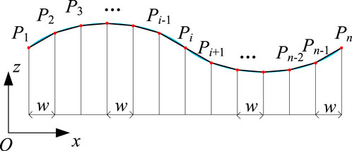
FIGURE 10. Approximation of an arbitrary cylindrical surface.
Therefore, when the function of the directrix is given as F(x), the x and z coordinates of the fitting point Pi can be obtained as
4 Kinematic analysis
In this section, the kinematic model of the proposed kirigami-inspired deployable mechanism is established. Based on the position analysis, the feature of type preserving of the mechanism has been analyzed. Since the two methods have different approximations for cylindrical surfaces, they are discussed separately.
4.1 The method for approximating parabolic cylindrical surface
4.1.1 Position analysis
As shown in Figure 11, the coordinate system of the proposed deployable mechanism is established using the method for approximating parabolic cylindrical surfaces; the blue panels of the mechanism are always parallel to the plane O-YZ, while the red panels and green panels remain parallel to themselves, respectively. The origin O is located at the midpoint of the upper surface of the first unit of the mechanism. The lengths of the mechanism along the x-axis and y-axis change with the deployable angle θ. To reduce the analysis complexity, the position analysis is decomposed into two parts, namely motions on the plane O-XZ and O-YZ, respectively.
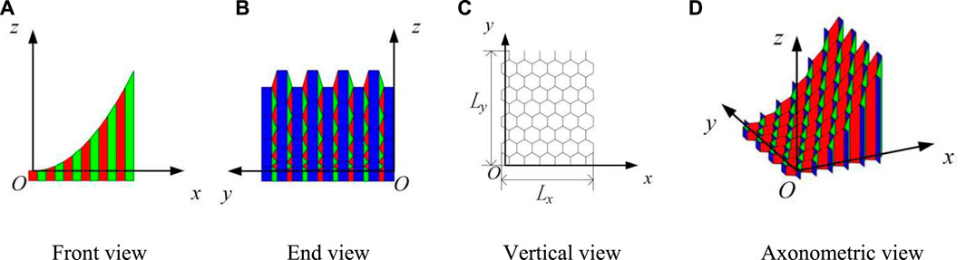
FIGURE 11. Coordinate system of the kirigami-inspired deployable mechanism using the method for approximating parabolic cylindrical surfaces (A) Front view (B) End view (C) Vertical view (D) Axonometric view.
Figure 12 presents the view on O-XZ of the mechanism. Lx indicates the length along the x-axis of the designed mechanisms. It only relates to the number of cells along the x-axis and the value of θ. The type of cell has no effect on Lx. Therefore, the Lx of the four networks in Figure 7 can be expressed as
where nx is the number of cells along the x-axis. The length Lx declines when the deployable angle θ decreases, namely it is compressed along the x-axis with the folding of the mechanism.
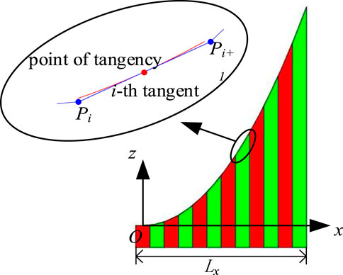
FIGURE 12. View on O-XZ.
The slope of the tangent and coordinates of the fitting point vary with the change of θ. According to the analysis of the basic cells and units, the slope ki of the ith tangent is
where θd is the deployable angle at the fully deployed configuration.
The coordinates of point Pi can be obtained as
where Pix and Piz represent the x and z coordinates of the point Pi; hi denotes the height of the corresponding cell.
The length Ly along the y-axis of the mechanism is determined by the number of cells, cell types, and the deployable angle. The number of positive Poisson’s ratio cells, negative Poisson’s ratio cells, and zero Poisson’s ratio cells along the y-axis is denoted as nhex, nr-hex, and ns-r-hex, respectively. The length Ly can be derived as
where
where Lθ is the sum of the lengths projected on the y-axis by edges that are not parallel to the y-axis; Ls is the sum of the lengths projected on the y-axis by edges that are parallel to the y-axis. Lθ varies with the deployable angle θ; Ls is constant during the deployment of the mechanism.
Lθ = 0 when the number of positive Poisson’s ratio cells is equal to the number of negative Poisson’s ratio cells along the y-axis. In this case, the length Ly of the mechanism will not change when the deployable angle varies, which illustrates that the Poisson’s ratio of the mechanism is zero. It can be seen that the networks of units in Figures 6C, D satisfy the condition. Similarly, the mechanism will show positive Poisson’s ratio if the number of positive Poisson’s ratio cells are more than the number of negative Poisson’s ratio cells along the y-axis. On the contrary, the mechanism shows the characteristic of negative Poisson’s ratio.
4.1.2 Analysis of type-preserving feature
Figure 13 presents the ith tangent of the mechanism at the deployed and intermediate states. The corresponding coordinates of these points and the slope of the tangent can be obtained with the above analysis.
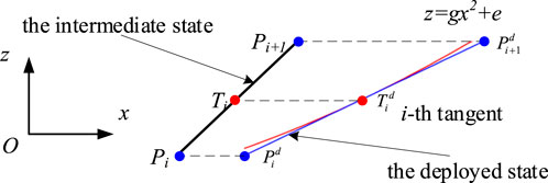
FIGURE 13. The i-th tangent at the deployed and intermediate states.
The relationship between the coordinates of Ti and Tid can be expressed as
The tangent point Tid is located on the fitting parabola. It can be derived as
where
Thus, the relationship between the x and z coordinates of Ti is
which means the tangent point Ti at the intermediate state is located at the parabola z = gmx +e.
The slope of a line, which is tangential to the parabola at the point Ti, can be calculated with the parabola coefficient gm and the coordinates of the point Ti. The slope is
which is consistent with that derived in Eq. 9.
Therefore, the mechanism is able to approximate a parabolic cylindrical surface at the intermediate state, which confirms the type-preserving feature of the mechanism.
4.2 The method for approximating arbitrary cylindrical surface
4.2.1 Position analysis
As shown in Figure 14, the coordinate system of the proposed deployable mechanism is established using the method for approximating an arbitrary cylindrical surface; the blue panels of the mechanism are always parallel to the plane O-YZ. The origin O is located at the lower surface of the first unit of the mechanism. The lengths of the mechanism along the x-axis and y-axis also change with the deployable angle θ. The position analysis is decomposed into two parts to reduce the analysis complexity, namely motions on the plane O-XZ and O-YZ, respectively.
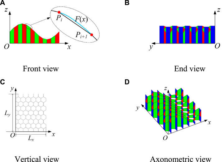
FIGURE 14. Coordinate system of the mechanism using the method for approximating an arbitrary cylindrical surface (A) Front view (B) End view (C) Vertical view (D) Axonometric view.
Figure 14C shows the vertical view of the mechanism; Lx and Ly indicates the length along the x-axis and y-axis of the designed mechanisms, respectively. The length Lx and Ly can be obtained through Eqs 8, 11, 12.
In addition, the Poisson’s ratio properties of this mechanism are the same as those of the mechanism approximating parabolic cylindrical surface.
4.2.2 Analysis of type-preserving feature
The fitting points Pi and Pi+1 of the mechanism at the deployed and intermediate states are shown in Figure 15. The corresponding coordinates of these points and the slope of the tangent can be obtained with the above analysis.
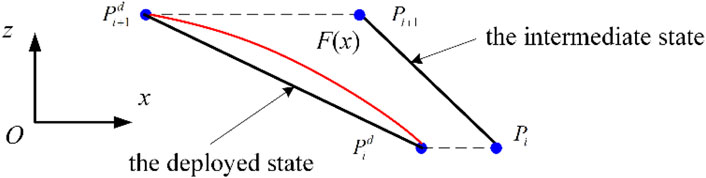
FIGURE 15. The fitting points Pi and Pi+1 of the mechanism at the deployed and intermediate states.
The relationship between the coordinates of the fitting points Pi and Pid can be expressed as
The fitting point Pid is located on the fitting cylindrical surface at the intermediate state. It can be derived as
where G (x) is the function for the directrix of the fitting cylindrical surface at the intermediate state, it can be represented as
Thus, combining with Eq. 17, it can be obtained that
Therefore, the mechanism is able to approximate the same type of cylindrical surface at the intermediate state, which confirms the type-preserving feature of the mechanism.
5 Case studies
In this section, three case studies are investigated. Kirigami-inspired deployable mechanisms with positive, negative, and zero Poisson’s ratios are presented, respectively.
5.1 Case I
The Poisson’s ratio of the network in this case is positive. The mechanism, which can approximate a parabolic cylindrical surface, is composed of the hexagonal units. Parameters of this case are presented in Table 1.

TABLE 1. The parameters of case I.
The length l1 of the cells mainly depends on processing requirements and structural strength. Since these two are not relevant in this case, the length l1 is set to 1 cm. The parameters of each cell are calculated using the method proposed in Section 4.1, as shown in Table 2.
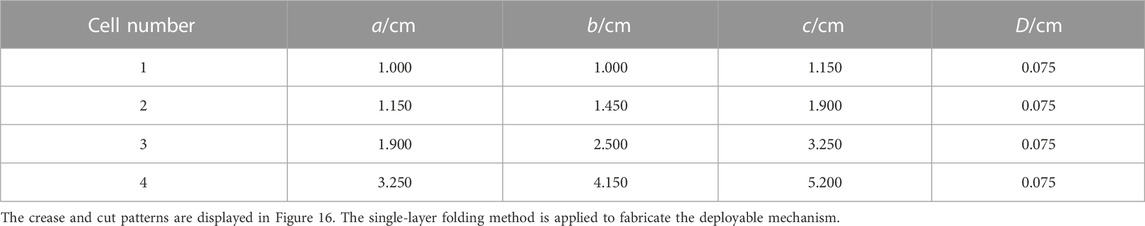
TABLE 2. The parameters of each cell of case I.
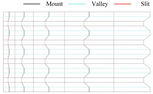
FIGURE 16. Crease and cut patterns of case I.
The obtained kirigami-inspired deployable mechanism is shown in Figure 17. The number of cells along the y-axis is 4. The mechanism is fully deployed when the deployed angle is 120°. The fitting parabola is y = x2/10 corresponding to θd = 120°.
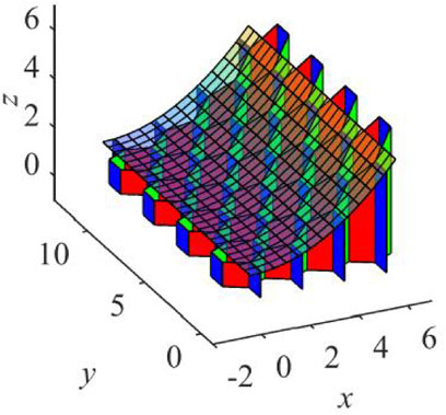
FIGURE 17. The kirigami-inspired deployable mechanism of case I.
The coefficient of the fitting parabola varies from 0.100 to 0.228 with the changing of the deployable angle θ from 120° to 70°. Figure 18 shows the fitting parabolas corresponding to different deployable angles. The mechanism can approximate different cylindrical surfaces with different θ.

FIGURE 18. The fitted parabola corresponding to θ.
The Poisson’s ratio of this case can be calculated through the kinematic analysis. The variation of Poisson’s ratio with the deployable angle is displayed in Figure 19, which is always positive.

FIGURE 19. Variation of Poisson’s ratio of case I.
5.2 Case II
The Poisson’s ratio of the network in this case is negative. Parameters of this case are the same as those in Case I. The crease and cut patterns are presented in Figure 20A. The single-layer folding method is applied to make the deployable mechanism.
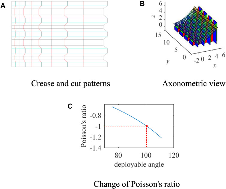
FIGURE 20. Case II with negative Poisson’s ratio (A) Crease and cut patterns (B) Axonometric view (C) Change of Poisson’s ratio.
Figure 20B shows the structure of the deployable mechanism. The mechanism is composed of the re-entrant hexagonal units. The number of cells along the y-axis is 4. At the fully deployed state, namely θd = 120°, the function of the approximated parabola is z = 0.1x (Ding et al., 2020). The mechanism can fit different parabolic cylindrical surfaces at the intermediate states.
Figure 20C displays the variation of the Poisson’s ratio with the deployable angle. The Poisson’s ratio of the mechanism is always negative, namely the length Ly declines with the decreasing of Lx. The configurations and approximated parabolic surfaces of the mechanism when θ = 120° or θ = 50° are shown in Figure 21.
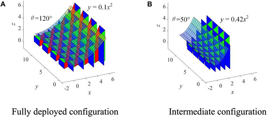
FIGURE 21. The kirigami-inspired deployable mechanism of case II (A) Fully deployed configuration (B) Intermediate configuration.
5.3 Case III
The proposed kirigami-inspired mechanism in this case is presented in Figure 22. The network consists of the three kinds of basic cells. The fitting surface of the mechanism is always a parabolic cylinder. The Poisson’s ratio of the mechanism is zero, i.e. Ly remains the same when the mechanism deploys or folds.
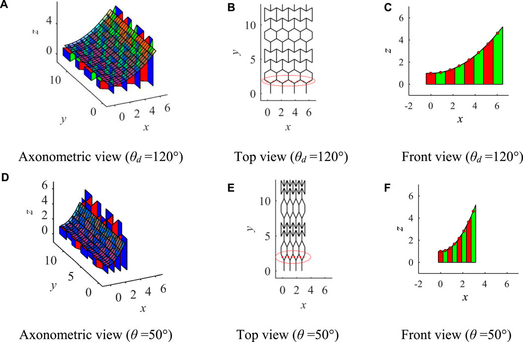
FIGURE 22. Case III with zero Poisson’s ratio (A) Axonometric view (θd = 120°) (B) Top view (θd = 120°) (C) Front view (θd = 120°) (D) Axonometric view (θ = 50°) (E) Top view (θ = 50°) (F) Front view (θ = 50°).
The X and Z coordinates of the fitting points (red dots) circle in the red and the Z coordinates of the fitted parabolic cylindrical surface under the corresponding X coordinate are illustrated in Tables 3, 4. The fitted directrix are z = 0.1000x2 + 1 and z = 0.4199x2+1 at θ = 120° and θ = 50°, respectively. These fitting points are numbered from left to right. During the deploying process, the fitting points are always on the fitted directrix.
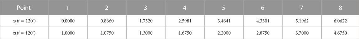
TABLE 3. The X and Z coordinates of fitting points surrounded by a red circle in case III (θ = 120°).
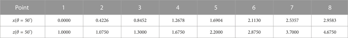
TABLE 4. The X and Z coordinates of fitting points surrounded by a red circle of case III (θ = 50°).
5.4 Case IV
The Poisson’s ratio of the network in this case is zero. The mechanism can approximate a cylindrical surface with sine curve as the directrix. Parameters of this case are presented in Table 5.

TABLE 5. The parameters of case IV.
The proposed kirigami-inspired mechanism in this case is presented in Figure 23. The network is the same as case III. The fitting surface of the mechanism is always a cylindrical surface with sine curve as the directrix. The Poisson’s ratio of the mechanism is zero, i.e. Ly remains the same when the mechanism deploys or folds.
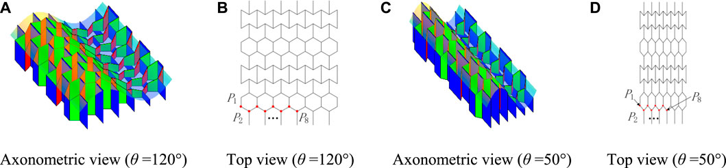
FIGURE 23. Case IV with zero Poisson’s ratio (A) Axonometric view (θ = 120°) (B) Top view (θ = 120°) (C) Axonometric view (θ = 50°) (D) Top view (θ = 50°).
According to Eq. 18, G (x) can be represented as
The X and Z coordinates of the fitting points (red dots) and the Z coordinates of the fitted parabolic cylindrical surface under the corresponding X coordinate are illustrated in Tables 6, 7. The fitted directrix are F (x) and G (x) at θ = 120° and θ = 50°, respectively. These fitting points are numbered from left to right. During the deploying process, the fitting points are always on the fitted directrix.

TABLE 6. The X and Z coordinates of fitting points in case Ⅳ (θ = 120°).
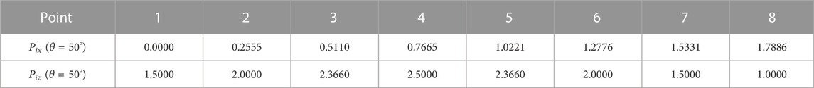
TABLE 7. The X and Z coordinates of fitting points of case Ⅳ (θ = 50°).
6 Conclusion
A novel kirigami-inspired deployable mechanism with a type-preserving feature and controllable Poisson’s ratio is proposed in this paper. Three basic cells with different Poisson’s ratios, e.g., the hexagonal cell, re-entrant hexagonal cell, and semi re-entrant hexagonal cell, are presented and studied. The single-layer-folding method is utilized to obtain the 3D cell from flat paper. Deployable mechanisms with positive, negative, and zero Poisson’s ratios are obtained by the network of the basic units. Two geometric methods are proposed to obtain the parameters to approximate a cylindrical surface. One method is specifically designed to approximate parabolic cylindrical surfaces, while the other is suitable for approximating arbitrary cylindrical surfaces. Kinematic analysis of the mechanism is performed. The characteristic of type preserving is proved, which illustrates the mechanism can fit an arbitrary cylindrical surface not only at the fully deployed state but also at the intermediate state. Four cases with different Poisson’s ratios are performed and simulations are conducted to verify the feasibility of the design and analysis. The main advantages of the proposed mechanism are type-preserving and controllable Poisson’s ratio, which makes it well-suited for deployment on commercial satellites that undergo constant mission variations. In future research, the incorporation of thick-panel origami can be considered in the design of mechanisms. Furthermore, exploring the development of simple drive systems for such mechanisms would also be a promising avenue for further investigation.
Data availability statement
The raw data supporting the conclusion of this article will be made available by the authors, without undue reservation.
Author contributions
JW: data curation, formal analysis, investigation, methodology, software, visualization, writing-original draft; HX: supervision, writing-review and editing; XD: funding acquisition, project administration, resources; SL: conceptualization, funding acquisition, validation, writing—review and editing. All authors contributed to the article and approved the submitted version.
Funding
This work has been supported by the National Natural Science Foundation of China (Grant Nos 52075016, 52222501, 52105004, and 52192632) and the State Key Laboratory of Robotics and Systems (HIT) under Grant SKLRS-2022-KF-02.
Conflict of interest
The authors declare that the research was conducted in the absence of any commercial or financial relationships that could be construed as a potential conflict of interest.
Publisher’s note
All claims expressed in this article are solely those of the authors and do not necessarily represent those of their affiliated organizations, or those of the publisher, the editors and the reviewers. Any product that may be evaluated in this article, or claim that may be made by its manufacturer, is not guaranteed or endorsed by the publisher.
References
Broccolo, S., Laurenzi, S., and Scarpa, F. (2017). AUXHEX – a kirigami inspired zero Poisson's ratio cellular structure. Compos. Struct. 176, 433–441. doi:10.1016/j.compstruct.2017.05.050
Calisch, S. E., and Gershenfeld, N. A. (2018). Towards continuous production of shaped honeycombs. Proc. ASME 2018 13thInternational Manuf. Sci. Eng. Conf. 3. doi:10.1115/MSEC2018-6646
Dai, L., and Xiao, R. (2020). Optimal design and analysis of deployable antenna truss structure based on dynamic characteristics restraints. Aerosp. Sci. Technol. 106, 106086. doi:10.1016/j.ast.2020.106086
Ding, X., Xiao, H., Yang, Q., Li, L., and Xu, K. (2020). Design and analysis of a cable-winding device driving large deployable mechanisms in astrophysics missions. Acta Astronaut. 169, 124–137. doi:10.1016/j.actaastro.2020.01.004
Duan, B. (2020). Large spaceborne deployable antennas (LSDAs)—a comprehensive summary. Chin. J. Electron. 29 (1), 1–15. doi:10.1049/cje.2019.09.001
Grima, J. N., Oliveri, L., Attard, D., Ellul, B., Gatt, R., Cicala, G., et al. (2010). Hexagonal honeycombs with zero Poisson's ratios and enhanced stiffness. Adv. Eng. Mater. 12 (9), 855–862. doi:10.1002/adem.201000140
Li, J., Qin, Q., and Zhang, J. (2021). Internal blast resistance of sandwich cylinder with lattice cores. Int. J. Mech. Sci. 191 (2021), 106107. doi:10.1016/j.ijmecsci.2020.106107
Lim, J. H., Kim, Y. B., Jang, I. S., Kim, H., and Oh, H. U. (2022). Parabolic deployable mesh antenna with a hingeless system of superelastic SMA ribs and composite tape springs. Acta Astronaut. 200 (2022), 149–162. doi:10.1016/j.actaastro.2022.08.007
Lyu, S., Qin, B., Deng, H., and Ding, X. (2021). Origami-based cellular mechanical metamaterials with tunable Poisson's ratio: construction and analysis. Int. J. Mech. Sci. 212 (2021), 106791. doi:10.1016/j.ijmecsci.2021.106791
Neville, R. M., Chen, J., Guo, X., Zhang, F., Wang, W., Dobah, Y., et al. (2017). A kirigami shape memory polymer honeycomb concept for deployment. Smart Mater. Struct. 26, 05LT03. doi:10.1088/1361-665x/aa6b6d
Nojima, T., and Saito, K. (2006). Development of newly designed ultra-light core structures. JSME Int. A 49, 38–42. doi:10.1299/jsmea.49.38
Ramadoss, V., Zlatanov, D., Ding, X., Zoppi, M., and Lyu, S. (2019). Design, construction and control of curves and surfaces via deployable mechanisms. J. Mech. Robotics 11 (6), 1–17. doi:10.1115/1.4044734
Saito, K., Pellegrino, S., and Nojima, T. (2014). Manufacture of arbitrary cross-section composite honeycomb cores based on origami techniques. ASME International Design Engineering Technical Conferences & Computers & Information in Engineering Conference. 136(5), doi:10.1115/DETC2013-12743
Shi, C., Guo, H., Cheng, Y., Liu, R., and Deng, Z. (2021b). Design and multi-objective comprehensive optimization of cable-strut tensioned antenna mechanism. Acta Astronaut. 178 (2021), 406–422. doi:10.1016/j.actaastro.2020.09.031
Shi, C., Guo, H., Zhang, S., Liu, R., and Deng, Z. (2021a). Configuration synthesis of linear foldable over-constrained deployable unit based on screw theory. Mech. Mach. Theory 156 (2021), 104163. doi:10.1016/j.mechmachtheory.2020.104163
Xiao, H., Lyu, S., and Ding, X. (August 2018). Design and analysis of a cable-driven deployable cylindrical mechanism. Proceedings of the ASME 2018International Design Engineering Technical Conferences and Computers and Information in Engineering Conference, Quebec City, Canada, doi:10.1115/DETC2018-85575
Xiao, H., Lyu, S., and Ding, X. (2020). Optimizing accuracy of a parabolic cylindrical deployable antenna mechanism based on stiffness analysis. Chin. J. Aeronautics 33 (5), 1562–1572. doi:10.1016/j.cja.2019.05.017
Keywords: kirigami, deployable mechanism, type preserving, controllable Poisson’s ratio, cylindrical surface
Citation: Wang J, Xiao H, Ding X and Lyu S (2023) Kirigami-inspired deployable mechanisms with a type-preserving feature and controllable Poisson’s ratio. Front. Mech. Eng 9:1225682. doi: 10.3389/fmech.2023.1225682
Received: 19 May 2023; Accepted: 10 October 2023;
Published: 16 November 2023.
Edited by:
Andreas Mueller, Johannes Kepler University of Linz, AustriaReviewed by:
Fengyu Xu, Nanjing University of Posts and Telecommunications, ChinaNicola Cappetti, University of Salerno, Italy
Copyright © 2023 Wang, Xiao, Ding and Lyu. This is an open-access article distributed under the terms of the Creative Commons Attribution License (CC BY). The use, distribution or reproduction in other forums is permitted, provided the original author(s) and the copyright owner(s) are credited and that the original publication in this journal is cited, in accordance with accepted academic practice. No use, distribution or reproduction is permitted which does not comply with these terms.
*Correspondence: Shengnan Lyu, c2hlbmduYW5fbHl1QGJ1YWEuZWR1LmNu