 Julius B. Mathews
 Jonas Rachner2†
- 1Fraunhofer Institute for Production Technology IPT, Department of Production Quality and Production Metrology, Aachen, Germany
- 2Laboratory for Machine Tools and Production Engineering (WZL), RWTH Aachen University, Chair of Production Metrology and Quality Management, Aachen, Germany
In manufacturing, rising demands for customized products have led to increased product variance and shortened product life cycles. In assembly lines, an increased variant diversity impedes the product flow. As a result, the utilization of assembly resources decreases, and production costs grow. An approach to increase the flexibility and adaptability of the assembly system is the implementation of the concept of line-less assembly. In the first step, the assembly line is dissolved. Then, stations are reallocated and linked by automated guided vehicles resulting in a loosely coupled layout, for example, a parallelization and interconnection of multiple lines or a matrix layout. A key requirement for the successful operation and control of a line-less assembly system is the collection and correct interpretation of data. To fully exploit the flexibility and adaptability of the concept of line-less assembly, a software architecture for planning and control must base on an information model allowing the fast integration of all shop floor assets and other data resources. Therefore, a modular data model with standardized interfaces for interoperable data exchange like a digital twin is needed. The aim of this paper is the development and implementation of a software architecture for planning and control of a line-less assembly system. Moreover, the architecture should integrate an interoperable digital twin of the physical system. To satisfy the criteria of interoperability and fast deployment, the digital twins are evolved following the methodology of a digital twin pipeline. Furthermore, a physical demonstrator serves as a testbed for the developed software architecture and digital twins. On the level of production planning and control, relevant industrial applications are identified and implemented in the form of use cases to show the functionality of the line-less assembly system as cyber-physical production system.
1 Introduction and motivation
In manufacturing, rising demands for customized products have led to increased product variance and shortened product life cycles (Hu, 2013; Ren et al., 2018). In line assembly, numerous product variants and small batch sizes conclude in a higher variance in process times impeding the product. As a result, the utilization of assembly resources decreases, and production costs grow. This effect is further amplified by downtimes caused by reconfigurations due to the scaling of assembly resources to fit changing customer demands. Moreover, emerging disruptions hamper the entire product flow because all individual stations and operations are rigidly interconnected (Lotter and Wiendahl, 2012; Qamar et al., 2018; Li et al., 2021).
An approach to increase the flexibility and adaptability of the assembly system is the implementation of the concept of a line-less assembly system (LAS) (Hüttemann et al., 2017). In the first step, the assembly line is dissolved. Then, assembly resources are repositioned freely on the shop floor and linked by automated guided vehicles (AGVs) resulting in a loosely coupled layout. Examples are the parallelization of multiple lines or a matrix layout. Now, each product follows an individually optimized processing route through the assembly resources (Hüttemann et al., 2016; Hüttemann et al., 2019).
Key requirements for the successful operation of a LAS are the handling of the complex material flow by AGVs, the integration of assembly workers into the production process, and integrated production planning and control algorithms. Furthermore, these requirements presuppose a suitable digital representation of all shop floor assets and other data resources like a digital twin (DT) (Hüttemann et al., 2019). A DT is defined as the digital representation of a real object, service, or intangible asset (Stark and Damerau, 2019). The digital and physical objects are connected by a fully integrated and automatic data flow to exchange information (Kritzinger et al., 2018). To fully exploit the flexibility of the concept of LAS, the DT must base on a modular information model with standardized interfaces for interoperable data exchange allowing the fast integration of new entities (Göppert et al., 2021a). Since the benefits and potentials of the concept of LAS have been investigated and approved in simulations (Schönemann et al., 2015; Hofmann et al., 2019; Buckhorst and Schmitt, 2020; Hüttemann, 2021; Rachner et al., 2022b), current research is concerned with the implementation of LASs as a cyber-physical production system (CPPS). CPPS consists of intelligent and connected assets and subsystems that acquire information from their production environment and act autonomously in response to internal and external changes in the production system (Monostori et al., 2016). To operate a LAS as CPPS, a software architecture for planning and control is needed for three reasons:
1. Connection and adaptive control of all shopfloor assets
2. Dynamical adjustments of the assembly process
3. Providing worker assistance based on the selected technology, product variant, etc.
Therefore, the software architecture is responsible for the assignment of products to assembly resources. This decision is based on the status of the CPPS and information about the product requirements and the abilities of the workstations all given by a DT. For the implementation of a planning and control system, various centralized and decentralized control architectures exist (Göppert et al., 2021c). In the context of LAS, there is a gap in research of a software architecture for the planning and control of a LAS that fully integrates an interoperable DT.
Accordingly, the aim of this paper is the development and implementation of a software architecture for planning and control of a LAS. Moreover, the architecture should integrate an interoperable DT of the CPPS. To satisfy the criteria of interoperability, the DTs are evolved following the methodology of the Digital Twin Pipeline introduced by (Göppert et al., 2021a). As part of the research project “AIMFREE” (Rachner et al., 2022a), a LAS demonstrator is built and installed where several variants of a car’s drive battery module are assembled. Following the production paradigm of line-less assembly, the CPPS consists of multiple partially automated assembly stations connected by AGVs that handle all logistics processes. Accordingly, the LAS demonstrator serves as a testbed for the developed software architecture and DTs. Therefore, relevant industrial applications are identified and implemented in the form of use cases to show the functionality of the LAS as CPPS.
After introducing and motivating this research, the fundamentals and the state of the art are explained in Foundation and State of the Art. In this section, the requirements for the control system of a LAS are assessed and different software architectures for planning and control of a LAS are analyzed and evaluated. Furthermore, DTs in LAS and the DT Pipeline are introduced, and communication standards and protocols are presented. Consequently, required developments based on the gap in the state of the art are derived. In the Section Conceptual Design of a Software Architecture for Line-less Assembly, an overview of the developed software architecture for LAS is given and subsequently described in detail. Furthermore, the LAS demonstrator is presented, and the identified use cases are implemented to illustrate the functionality of the whole CPPS in the section Use-Case-Based Implementation of the Developed Software Architecture. In Conclusion and Outlook, the results of the presented work are summarized and an outlook for further research opportunities is shown.
2 Foundation and state of the art
This section describes the required foundations for the development and implementation of the software architecture. In addition, the DT Pipeline, and further relevant topics like the concept of DTs, ontologies, meta-models and communication standards and protocols are introduced.
2.1 Architectures for planning and control of flexible systems
A key factor for the efficient operation of LAS is the software architecture for planning and control. To exploit the full potential, it is essential to consider the current production situation with regard to the available capacities in the assembly system (Greschke, 2015). It can be realized in a centralized or decentralized architecture. On the one hand, centralized architectures are based on the flexible job shop problem and achieved better results in simulations in regard to tardiness and lead time (Bochmann, 2018; Burggräf et al., 2020; Schukat et al., 2022). On the other hand, decentralized architectures are mainly modeled as multi-agent systems (MAS) and promise high efficiency and almost real-time performance (Günthner and Hompel, 2010; Libert et al., 2010; Leusin et al., 2018; Mayer et al., 2019; May et al., 2021). A generalized software architecture for the planning and control of LAS is described by Rachner et al. (2020). It includes a centralized control system, a middleware for interacting with data models, and fleet management for AGVs. Jung et al. (2018) define a service-oriented architecture for communication and control of LAS. It includes the autonomous integration of assembly resources into the software system and the creation and execution of individual product routes and process steps (Jung, 2023). Buckhorst et al. (2022) present a decentralized holonic control system model for LAS, that extends the flexibility by mobilization of all resources. Nielsen et al. (2023) developed a control system architecture for LAS with consideration of reconfigurable work cells and AGVs based on simulation results (Nielsen et al., 2023). Boccella et al. (2020) compare centralized and decentralized control systems for flexible manufacturing systems and conclude that centralized control is the best solution only for deterministic and predictable scenarios and a more flexible control is better in case of a higher vulnerability to errors. A Service-oriented Architecture (SoA) for reconfigurable production systems is presented by Mendes et al. (2008) that provides control logic and functionalities of components encapsulated in software modules that respond to specific requests to dynamically compose complex process sequences using temporally and spatially distributed abilities.
As individual job routes are a central attribute of LAS, scheduling is a key factor. It consists of the assignment of station capabilities to product requirements (matching) and the decision on the process-station combination (routing). To meet the dynamic requirements with possible events such as machine breakdowns, predetermined production schedules are not sufficient, since the computing time is usually too long for short-term rescheduling. A solution to this problem is reactive online scheduling algorithms and predictive-reactive scheduling (Gupta et al., 2016; Echsler Minguillon, 2020; Göppert et al., 2021b). To implement online scheduling, a modular framework should be provided within the software architecture. One example is the server-based connection of the scheduling algorithm via RestAPI. This allows individual algorithms to be developed and adapted according to the key performance indicators (KPIs) to be optimized. In addition, the algorithm can be used modularly for real systems and simulation models, e.g., for training AI algorithms in a simulation environment (Rodič, 2017; Göppert et al., 2021b; Göppert et al., 2022).
All approaches have in common that a solid data basis is needed to enable adaptive control and to be aware of the current production status at any time. A DT can enable the data foundation and integrate production planning and control. One approach to creating and using DTs is the DT Pipeline.
2.2 Digital twin pipeline and communication protocols
The DT Pipeline is a method for the standardized and structured development of a DT (Göppert et al., 2021a). The end-to-end pipeline lowers the threshold for creating and deploying DT using well-established workflows for machine learning models. The holistic implementation of a DT for planning and control in CPPS is conducted in three phases as presented in Figure 1. In the first phase, a domain expert develops a suitable use case ontology based on established ontologies and meta-models. The custom ontology is then edited in an ontology editor (e.g., Protegé) and exported in JSON Schema files. Second, in the standardized modeling phase, a model generator for developing a use case-specific description model is used. The resulting description model follows the ontology schema files and comprises static information use case data, e.g., the maximum speed of an AGV or product route definitions. Finally, the automated deployment of the DT, including a communication processor connecting the DT with the physical system is conducted. Generative programming is used to generate the DT, based on the defined description model. The digital representation is communicated to all systems involved via the communication processor. Specifically, the DT can communicate with other entities, process control instructions, and update the description model with dynamic information (e.g., the process progress of a product). (Göppert et al., 2021a).
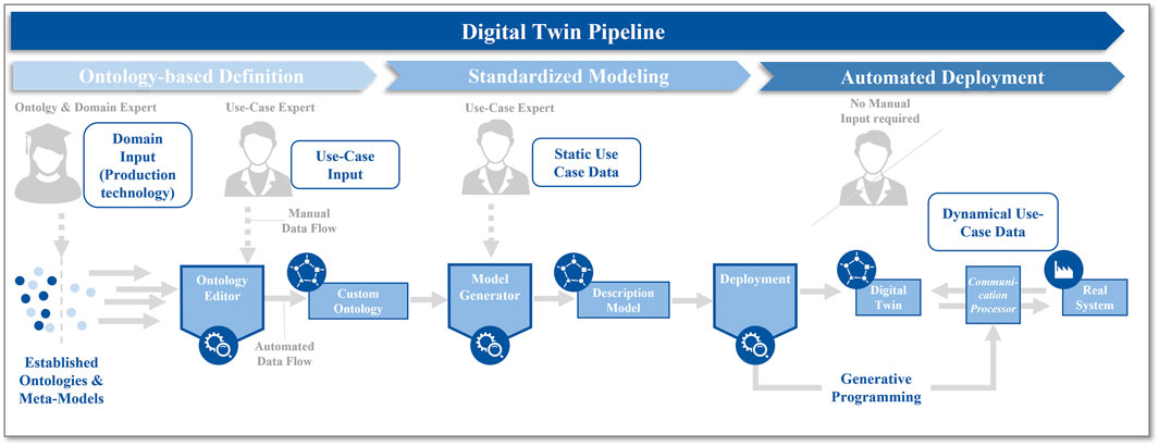
FIGURE 1. Three phases of the end-to-end Digital Twin Pipeline for the application in cyber-physical systems (cf. Göppert et al., 2021a).
The communication processor is implemented using communication protocols of the transport layer of the industrial internet of things connectivity stack model, such as the MQTT protocol (Yassein et al., 2016; Joshi et al., 2017). Moreover, communication processors using the OPC UA standard are developed. The MQTT protocol is based on the easy-to-implement publish-subscribe principle, which enables one-to-many, device-to-device, and many-to-one data transmission using so-called topics. (Banks et al., 2019). OPC UA distinguishes between clients and servers for communication, also using the publish-subscribe principle or the request pattern. (OPC Foundation, 2022).
To unleash the potentials of a LAS, a software architecture is required that is modularly extensible and enables scalability and robustness of the assembly system as much as the concept of line-less assembly. In software development, a SoA is a powerful software design to create a modular and loosely coupled software system which is able of providing the needed flexibility for the underlying production system. Furthermore, the low coupling of software modules allows the software architecture to easily scale with the production system. To reduce the integration and adaptation efforts of resources and products, the software architecture must rely on interoperable DTs. The use of the DT Pipeline ensures fast and standardized creation and deployment of DTs. Accordingly, the MQTT and OPC UA communication protocols take a decisive role in the standardization of all interfaces.
3 Conceptual design of a software architecture for line-less assembly
In the following, a generalized software architecture for planning and controlling LAS is proposed and presented. As depicted in Figure 2, the architecture is divided into nine loosely coupled main modules showing their main functionalities and the physical assets on the base layer. According to their distinct role, the modules are structured according to the layers of the Reference Architecture Model for Industry 4.0 (RAMI 4.0) which is a framework for implementing Industry 4.0 in manufacturing and production systems (DIN SPEC 91345 2016).
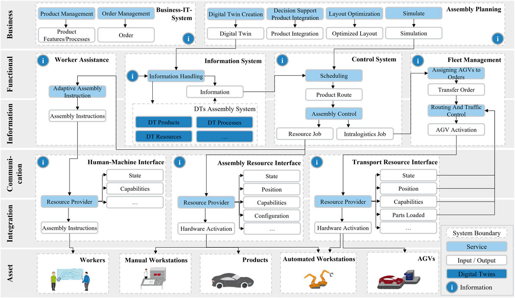
FIGURE 2. Software architecture for planning and controlling line-less assembly systems including digital twins.
In the business layer depicted in Figure 2, the assembly planning module is responsible for creating DTs by triggering the DT pipeline. Furthermore, it provides discrete-event simulation models based on current data, which can be used for planning resources and optimizing production layouts. If new products are introduced into the production system, the decision support suggests an adjusted system configuration. Order and product management are handled by higher-level business IT systems.
The two central elements of the architecture are the information system and the control system. Firstly, the information system is responsible for data management and presents an organized view of the different information flows within the production control network. Furthermore, a submodule of the information system contains the created DTs of the assembly system. They are updated with data collected from all modules. Moreover, the information system provides information in a way that is relevant to the task at hand e.g., the scheduling of the control system. Secondly, the control system is responsible for managing the technical operations, controlling the flow of production, and executing orders. For each individual product, a reactive scheduling algorithm creates an individual product route matching product requirements and system capabilities based on the current system state. Subsequently, the control system sends the next process step to the needed assembly resources and the fleet management to activate the following modules.
The fleet management module controls all intralogistics processes like the transport of materials or products. Based on availability, location, and fit for the transportation task, it assigns an appropriate AGV to the incoming transport job. The routes of the AGV are planned regarding the current locations of all AGVs. Then, the chosen AGV is activated and the current traffic of all transportation units is controlled. The worker assistance module uses process information to adaptively provide assembly instructions based on the selected technology, product variant, and skill level of the worker at the respective station.
In a service-oriented architecture, each production resource makes its capabilities available through generic, self-contained, and customizable services. However, production resources have a variety of interfaces that are specific to the vendor and hardware. To address this, the interfaces for human-machine interaction, assembly resources, and transport resources act as software intermediary that hides the specific details of how the services are executed. The main component of this system is the resource provider, which is specific to the hardware and adds a consistent and meaningful structure and description to the vendor- and hardware-specific protocols. This structure and description may vary depending on the needs of the production network and can include both dynamic conditions, such as the resource’s state and position, and static conditions, such as its capabilities.
Table 1 shows a qualitative comparison of existing software architectures with the one presented. The selection is limited to architectures developed for line-less assembly systems. While high scalability and modularity are given in all architectures, they differ in the focus on the DT and the effortless integration of new products, stations, and AGVs, which are particularly emphasized in the architecture presented here and are presented in Section 4. The consideration of automated simulation models, 3D visualization, and worker assistance, in particular, is only given to a limited extent.
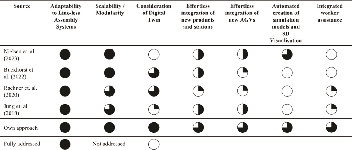
TABLE 1. Comparison of architectural approaches for planning and controlling of line-less assembly systems.
Unlike the approaches described in Section 2, the developed software architecture not only emphasizes that the DT of the assembly system is a fundamental requirement for planning and controlling a LAS but it integrates the creation and management of DTs into the architectural design. Additionally, the architecture depicts that workers are a valuable resource in LAS and addresses their specific needs by providing them with tailored information, such as adapted assembly instructions, through the worker assistance module.
4 Use-case-based implementation of the developed software architecture and digital twins
The developed software architecture is implemented in the LAS demonstrator which is set up as part of the research project “AIMFREE”. First, the components and layout of the demonstrator are described. Then, the implemented instance of the software architecture is introduced. In addition, the custom ontology and description model used for the creation of the DTs are described. As illustrated in Figure 3, four use cases are selected which are relevant for the planning level (cf. Figure 3, use case 4) respectively the control level (cf. Figure 3, use cases 1–3) of the LAS. Their implementation is used to clarify the application of the developed software architecture and DTs.
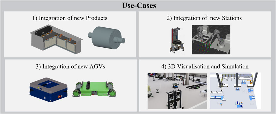
FIGURE 3. Introduction of the four selected industrial use cases.
4.1 Physical line-less assembly demonstrator
In the demonstrator, several variants of a battery module are assembled. The layout of the individual stations is shown in Figure 4. It consists of three manual assembly stations, a partially automated assembly station, an end-of-line section, and a warehouse. All manual assembly stations include a worktable with a shelving system to provide small materials like screws and hoses and tools and a tablet holder. On the tablet, interactive worker assistance software navigates the worker through the assembly procedures. Accordingly, all process steps of manual assembly and quality inspection are carried out at these stations. In addition, the partially automated assembly station consists of a working zone, a PLC, and a smart cordless screwdriver. At this resource, all automatic screwdriving processes with preset torque and inline quality control are executed by a worker and controlled by the PLC. Furthermore, the end-of-line section is an area for the last quality check and the warehouse for loading, unloading, and storing materials. All assembly stations are connected via a driverless transportation system which includes several freely navigating AGVs handling material and product logistics. In Figure 4, possible product and material flows are indicated by colored lines. The respective rectangles mark source and destination station. All in all, the individual assembly stations can perform both identical and differing assembly processes, thus processing can be partially parallelized. As a result, each battery module takes an individually optimized processing route through the LAS (cf. Mathews et al., 2022).
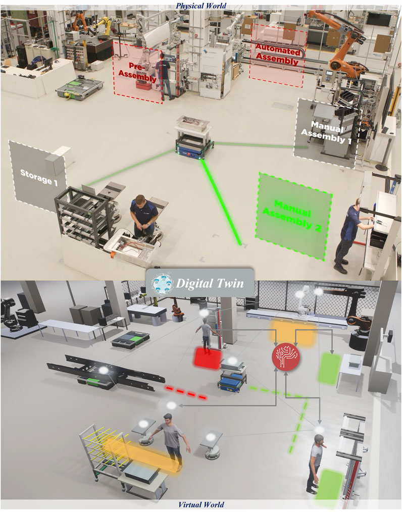
FIGURE 4. Physical and virtual representation of the line-less assembly demonstrator.
4.2 Implemented software architecture
Figure 5 shows the software architecture used in the demonstrator. In the higher-level planning system, discrete-event simulation was used to perform the layout of the system and the modeling of the DT. All communication is based on the MQTT protocol to ensure modular extensibility and adaptability in the sense of a service-oriented architecture. Therefore, the information flow is not strictly hierarchical because information can be distributed via the interfaces to various software modules and the information system. For a better overview the communication between interfaces and information system is not depicted in Figure 5. For automated stations, communication with a programmable logic controller (PLC) occurs. The information about new product variants, stations, or assembly and transport resources is directly fed into the system via MQTT and is considered for assembly (cf. Section Conceptual Design of a Software Architecture for Line-less Assembly). The following describes the sequence of an assembly process based on the software architecture. Except for the communication with the AGVs, all send MQTT messages follow the ontology and description model introduced in the following section.
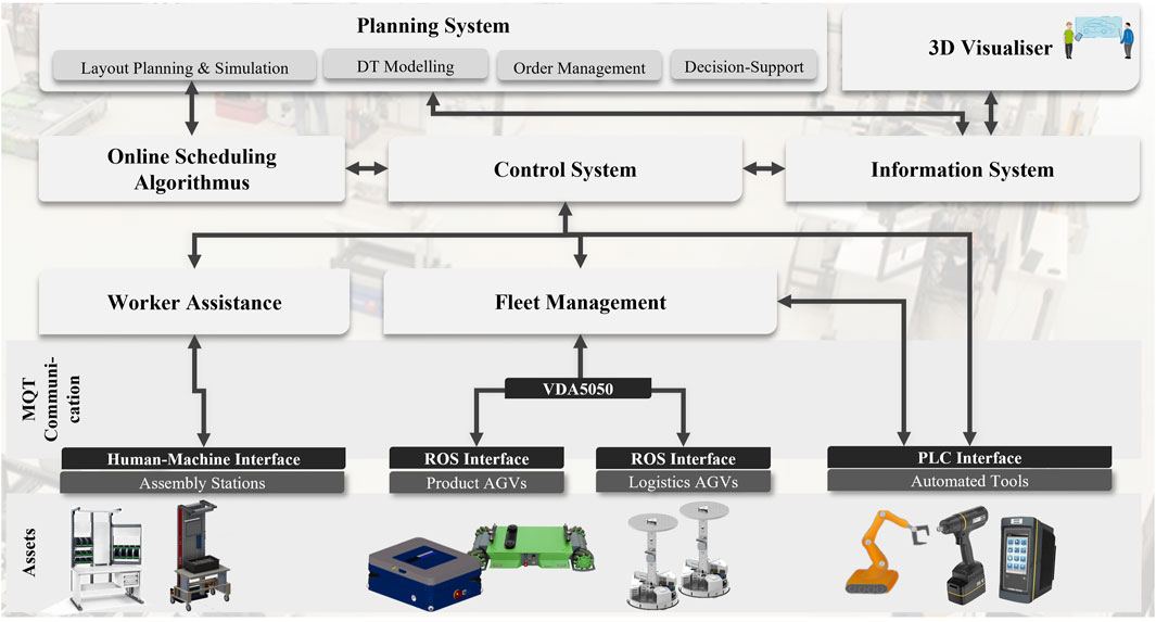
FIGURE 5. Implemented software architecture of the line-less assembly demonstrator.
The new order is started in the control system. There, the information on the MQTT topics of all existing jobs and stations is collected, processed, and forwarded to the reactive scheduling algorithm. In the demonstrator, a simple greedy algorithm is implemented, in which all possible processes for the order are matched with the availabilities and capabilities of the stations based on the precedence graph. From the possible combinations of process and station, the one with the lowest sum of waiting and transport time is then selected. The algorithm has a modular design so that it can also be used to predict decisions in simulation models (cf. Göppert et al., 2022).
The decision is reported back to the control system. For product transport, a message with the information about station and product information is forwarded to the Fleet Management, in which a map with a route network and stations is stored. After planning the optimal route, the information is sent to the corresponding AGV (product or material). The VDA 5050 guideline is used for communication since AGVs from three different manufacturers are used in the demonstrator. The control and localization of the AGVs are done locally, which is why conversion from MQTT to Robot Operating System (ROS) is implemented on the AGVs. The DT of the AGVs continuously reports location and status.
After the product has been transported to the station, the process to be executed is also sent to the Worker Assistance Module. Based on the information in the Assembly Station’s DT, the correct instructions are displayed based on process, worker, and product variant, and any test processes are recorded. For automated processes, a message is also sent to the station’s PLC to trigger entry and exit sequences and process execution. After confirming the completion of a process, the control system is triggered again and requests the scheduling server for the next process.
A 3D visualizer uses the data from the DT available on the MQTT broker to continuously provide a 3D image of the current assembly system and make current KPIs visible.
4.3 Custom ontology and description model of the line-less assembly demonstrator
As described in previous sections, the modules of the developed software architecture rely on the information given by the DTs of the LAS. To reduce the manual overhead for creating and deploying the DTs for the demonstrator, the introduced end-to-end pipeline is used. In the definition phase, a suitable use case ontology based on established ontologies and meta-models is developed. Figure 6 shows the extracted domain-specific custom ontology used for the demonstrator. Similar to Göppert et al. (2021a), on a structural level, the SOIL model (Bodenbenner et al., 2021) and asset administration shell (Boss et al., 2022) are used as a meta-model. On a domain level, the BOT ontology (Rasmussen et al., 2020) describes the general structure and elements of the shop floor and the MASON ontology (Lemaignan et al., 2006) defines products, processes, and resources. The main difference is a change in the overall structure of the custom ontology. Here, a product consists of a process and parts and follows the type of a product type. This enables the bundling of process steps into one process and the simple linking of a product to a process respectively its process steps. Additionally, each resource has capabilities that can be understood as a specific function the component is able to perform (Vathoopan et al., 2021). According to the idea of service-oriented architectures in production, capabilities are used as a standardized service that the control module of the software architecture can call and execute (DIN SPEC 91345 2016). In the control module, capabilities are utilized for the matching of a resource with the requirements of a process steps respectively product.
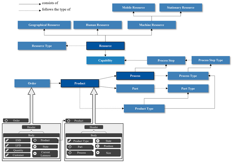
FIGURE 6. Extracted domain-specific custom ontology incorporating established ontologies and meta-models (cf. Göppert et al., 2021a).
In the modeling phase of the DT Pipeline, the presented custom ontology enriched with static use-case data is used as input for the model generator to create the description model of the demonstrator. To ensure that manual input follows the data structure given by the meta-model the model generator has a web-based user interface, as illustrated in Figure 7. The interface supports the creation of instances based on predefined types which are then directly available in machine-readable form. Thus, specific use-case instances like an order or a product can be modeled according to the predefined custom ontology, including all necessary parameters, variables, and components needed to describe the object. Relying on a meta-model ensures consistent modeling for the whole demonstrator because similar parameters in different contexts always follow the same structure. As shown in Figure 6, the instance of a product is created using the product type as a blueprint. On the one hand, every entity has a header including parameters to generally describe and uniquely identify the object. On the other hand, it has a body containing all information in the form of parameters, variables, and components. In addition, the product is linked to an order and its components respectively parts and process. Furthermore, the instance includes information about the current state, position, and size of the product which are important data for the control module and fleet management.
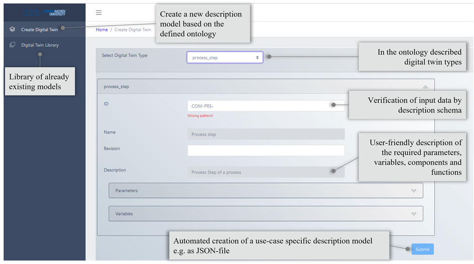
FIGURE 7. Web-based user interface of the model generator to ensure that the manual input follows the given data structure and is directly available in machine-readable form.
In the following section, the details of the DT Pipeline’s deployment phase are shown by the execution of the introduced use cases including the MQTT communication between the respective software modules.
4.4 Implemented industrial use cases
In this section, four use cases are selected to demonstrate the flexibility and adaptability of the LAS demonstrator. The integration of new products, workstations and AGVs are identified as relevant scenarios on the control level in flexible assembly. Thus, the deployment of the DTs and their interoperability can be shown. On the planning level, the integration of three-dimensional visualizations and simulations is chosen as use case. Especially model-based simulations can be utilized to plan future production scenarios or evaluate alternative system configurations based on the current information of the DT.
4.4.1 Integration of new products
LAS flexibly adapt to the frequent introduction of new products, product variants or changes of existing products. (Schmitt et al., 2017). The high integration frequency makes it necessary that the integration of a new product requires low effort. The modular software architecture in combination with the DT Pipeline makes this possible.
Figure 8 shows the workflow for integrating a new product into an existing system according to the DT pipeline. After a new product or product variant was developed in the product development phase, CAD files are used to directly derive all product data, including the precedence graph, for example by using assembly-by-disassembly algorithms (Münker and Schmitt, 2022). Further information on the product description can be added manually (e.g., process requirements such as torque). The corresponding description model is then created in the Model Generator (see Figure 10) and the new product type is deployed into the information system. The relevant data regarding the process requirements and components (e.g., hierarchical structure of the parts) is automatically sent to the corresponding topics via MQTT. These can be processed by all software modules in which the new information is required. All modules are connected in the presented software architecture and implement the changes when messages are published to the MQTT topic, in which product variants are described.
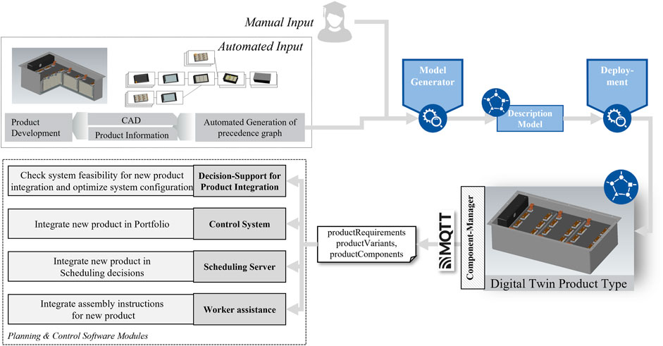
FIGURE 8. Workflow of integrating new product variants into a line-less assembly system using the Digital Twin Pipeline.
In the control system, the new product is directly added to the portfolio and the requirements are matched with the capabilities of the stations. In the scheduling server, these are then stored in the static data and taken into account in the subsequent decisions. With the static data of product type requirements added, orders with the new product variant can be scheduled.
As the introduction of a new product can also be accompanied by a shift in system capacities, the development of a decision support system is necessary in the future that matches the requirements of the product with the system’s capabilities. Considering various constraints such as ramp-up scenarios, station availability, or demand fluctuations, optimization algorithms can be used to find system configurations that enable the best possible assembly system configuration while considering all product types at the same time. To represent the complexity, modeling the configurations as a discrete-event simulation model, also on basis of the DT, is essential for the evaluation.
For the worker assistance module, assembly instructions can be automatically created based on the DT (Nuy et al., 2022) to be displayed at every manual workstation. Once the DT of a product type has been created, new orders can be generated which then correspond to the product type. These are recognized directly by the control system and scheduled to the stations accordingly.
4.4.2 Integration of new stations
LAS are designed to efficiently manufacture products with a lot of product variants and fluctuating customer demand. To ensure the system’s flexibility and ability to rapidly scale up and down, it should handle frequent changes of existing variants, the introduction of new products, or the elimination of older ones (Schmitt et al., 2017). Accordingly, integrating new production modules into the system or modifying existing ones should be done with minimal effort. This requirement is known by the term “plug-and-produce” (Bedenbender et al., 2017; Vogel-Heuser et al., 2017). The modular software architecture in combination with the DT Pipeline reduces the manual overhead for system integration.
Figure 9 depicts the workflow for integrating a new assembly resource into the existing LAS using the DT pipeline. First, factory planning identifies a change in product demand, thus it is necessary to scale the production output. Then, the new workstation is set up and all assets are physically connected to the network, either by using a cable or wireless connection. Depending on the device or type of connection, the network might need preparation for the reconfiguration beforehand. Existing information about the workstation, e.g., from the manufacturer or existing comparable resource types, is enriched with manually added data. As shown in Figure 10, manual input is simplified and standardized by the web-based user interface of the Model Generator. This ensures that entered data follows the given JSON schema and is directly available in machine-readable form. The corresponding description model is then created in the Model Generator and a new resource type and resource instance are deployed into the system. The relevant data regarding the workstation components and capabilities are automatically sent to the corresponding topics via MQTT. These can be processed by all software modules affected by the new information.
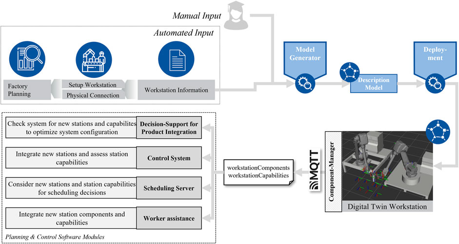
FIGURE 9. Workflow of integrating a new workstation into a line-less assembly system using the Digital Twin Pipeline.
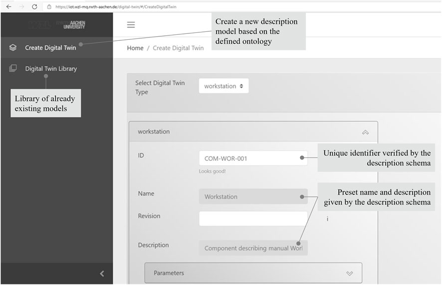
FIGURE 10. Web-based user interface of the model generator for new workstations.
In the control system, the new workstation is discovered, and the station’s capabilities are assessed in terms of identity, requirements, and consequences. A capability requirement can be the availability of a specific tool in the station. A capability consequence might be the update of a product’s DT and its linkage to the DT of the added part after an assembly operation is executed. If the resource includes space for storage, accepted materials and tools are evaluated. Subsequently, the resource is added to the list of connected and idle stations ready for assembly. In the scheduling server, the same information is stored in the static data and considered in the subsequent scheduling decisions. The matching of assembly jobs and stations is based on the static data enriched with information about the current state of all resources and processes in the LAS.
As the introduction of a new product can be accompanied by a demand for new or adapted workstation capabilities, the decision support system compares the requirements of the product with the system’s capabilities. The decision support alarms the user if no match is found. The worker assistance module integrates the components of the workstation and updates the DT in case of reconfigurations.
4.4.3 Integration of new AGVs
LAS become more flexible using AGVs for material and product transport. To enable easy scalability, easy integration of new AGVs is necessary. The modular software architecture in combination with the DT Pipeline makes this possible. The AGVs of different manufacturer types are connected to the fleet manager via a standardized VDA 5050-compliant communication interface (Kaven et al., 2022). The VDA 5050 specification aims to enable a manufacturer-independent integration of AGVs into one system. The specification defines a message structure and implements the MQTT communication protocol. Information on connection, state, order, visualization, and instantActions of the AGV is communicated via five topics. Combining these topics and the serial number enables the identification of incoming messages for an AGV. The syntax of the messages is based on the JSON format.
The VDA 5050 interface is implemented following the DT Pipeline (see Figure 11). It uses the introduced meta-model (cf. Section Custom Ontology and Description Model of the Line-less Assembly Demonstrator). The parameters and variables of an AGV are based on the communication contents of the VDA 5050 specification to grant compatibility. The AGV component thus consists of the submodels connection, order, state, instantActions, and visualization, which are assigned to a higher-level header. Modeling the use case instances in the pipeline’s second phase integrates static AGV data. A dynamic data exchange between DT and AGV is realized in the last phase, using an implemented Communication Processor.
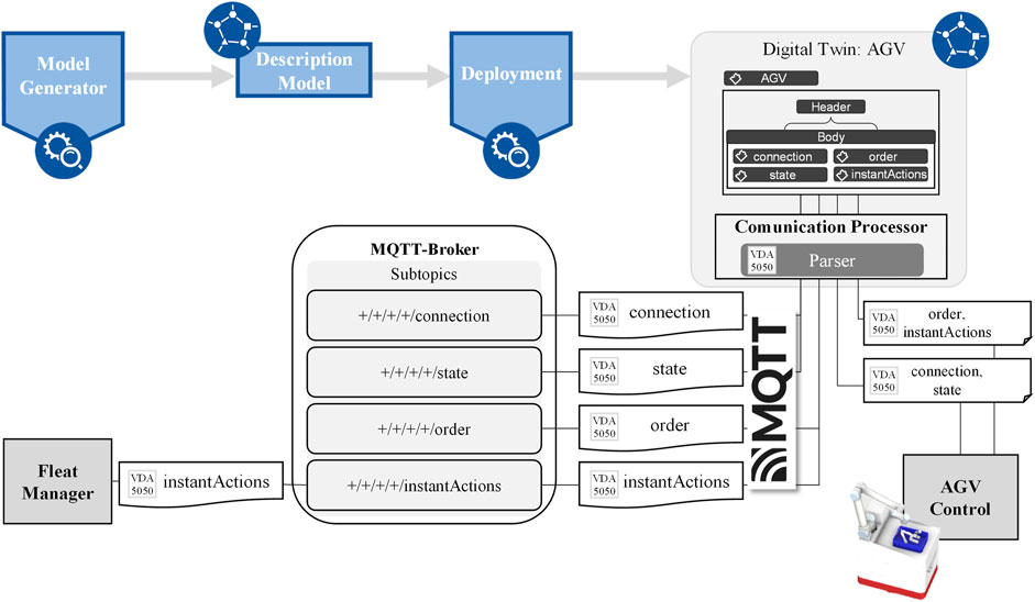
FIGURE 11. Workflow of AGV integration following the Digital Twin Pipeline and VDA 5050 specification.
With the initialization of the Communication Processor, the JSON file of the AGV’s digital model is read in and automatically converted into a Python object structure. This allows for easy access and updates of the generated objects and data. The Communication Processor establishes the connection to an MQTT broker for the exchange between the AGV and other components in the assembly system. MQTT topics are generated automatically, following the VDA 5050 recommended topic structure. To implement the connection between the physical world and the DT, the Communication Processor provides a schema parser converting messages into the VDA 5050 message schema before sending and into the DT format after receiving.
To execute a movement between two assembly stations of the demonstrator, the Communication Processor of the Fleet Manager publishes the motion task to the corresponding VDA 5050 subtopic. The AGV’s communication processor receives the transport order and updates the corresponding submodel of the DT. A motion task consists of a list of nodes on the shop floor. The nodes are defined within the internal AGV and fleet management models. The motion task is processed and executed using AGV internal localization techniques, e.g., SLAM. During execution, the current state of the AGV is updated in the corresponding submodel of the DT and published to the designated VDA 5050 subtopics.
Instant actions to be executed immediately (pause, continue) are published by the communication Processor of the Fleet Manager to the corresponding VDA-5050-compliant subtopic. The communication processor of the AGV receives the message, updates the data in the corresponding submodel of the DT, and forwards the message to the AGV via the integrated interface. During execution, the communication processor is informed of the current status of the AGV via the integrated interface to the AGV. The updated statuses are updated in the corresponding submodel of the DT and sent to the appropriate VDA-5050 compliant subtopics. To evaluate the model’s performance, the transition time between AGV and fleet manager was determined. The transmission time is defined as the time required for the transmission of the message from the sender to the receiver including encoding and decoding (Babovic et al., 2016). A Mosquitto MQTT broker was used within the implementation and 1,000 data points were sent at intervals of 0.5 s. The mean value of all determined transmission times was 54 m with a standard deviation of 62 m. The maximum value of the measured transmission times was 541 m, minimum value was 11 m. Outliers show delays that can be traced back to inadequate networks. (Kaven et al., 2022). Overall, the implemented model shows excellent applicability for the given use case but is not usable for real-time communication due to the inherent MQTT weaknesses.
4.4.4 Integration of 3D visualizations and simulation of the line-less assembly demonstrator
One important component of the DT is the linking of the physical world with the virtual world by employing discrete-event simulation models. In the demonstrator, the data is used to provide a simulation model of the demonstrator at any time, which can then be used, for example, to predict decisions or to evaluate alternative system configurations in a decision support system (see Figure 12). Since all relevant data for a simulation model (e.g., station capabilities, coordinates, product requirements, transportation systems) are available via MQTT, they are fetched on demand and converted by a Python script into an input file for automated scenario analysis. An interface is used to transfer the data to the simulation model (Tecnomatix Plant Simulation is used in this application), in which methods are implemented that read the input data in JSON format and automatically create the simulation model. With additional information of current orders and availabilities, the simulation model can represent the actual production system to predict future decisions.
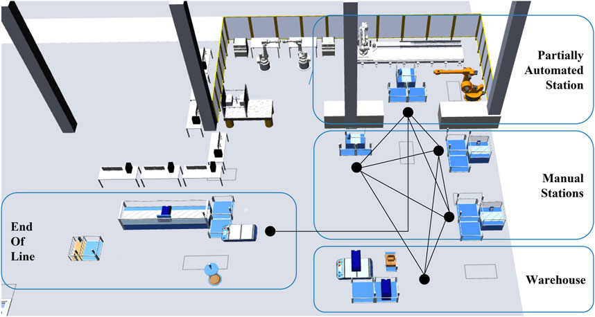
FIGURE 12. Discrete-event simulation model of the line-less assembly demonstrator (cf. Mathews et al., 2022).
The availability of all production data in the DT also enables the visualization of KPIs and the system status in dashboards. For better visualization, 3D data can additionally be consulted. In the demonstrator, a software program is used for this purpose, which uses the existing MQTT data on the corresponding topics to visualize the current assembly vividly based on a gaming engine. Thus, for example, the current positions of the AGVs can also be visualized and current data from the description model can be detected via mouse-over (see Figure 13).
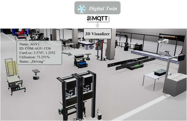
FIGURE 13. 3D visualization based on the digital twin using MQTT-parsed data.
5 Conclusion and outlook
The main goal of this research was the development and implementation of a software architecture for planning and control of a line-less assembly system. Moreover, the architecture should integrate an interoperable DT of the physical system. Various reference architectures, a methodology of an end-to-end Digital Twin Pipeline, and communication standards and protocols were presented as the foundation for developing the software architecture. The analysis of the state of the art showed that current research is concerned with the implementation of line-less assembly systems as cyber-physical production systems. To operate a line-less assembly, a software architecture is required that is modularly extensible and enables scalability and robustness of the assembly system as much as the concept of line-less assembly. Accordingly, a generalized software architecture for planning and controlling a line-less assembly system is proposed.
The developed software architecture is implemented in a line-less assembly demonstrator. The demonstrator serves as a testbed for the architecture and digital twins. First, the components and layout of the demonstrator are described in detail. Then, the implemented instance of the beforehand introduced software architecture is specified. Furthermore, the first two phases of the Digital Twin Pipeline are executed creating a custom ontology and description model used as an information model for the line-less assembly demonstrator and the creation of its digital twins. Finally, four use cases are selected which are relevant for the planning and control level of the line-less assembly demonstrator to illustrate the application of the developed software architecture and digital twins.
On the control level, the integration of new products, workstations, and AGVs are selected as the most relevant scenarios demonstrating the flexibility and adaptability of the assembly system. For each of the three use cases, the deployment phase of the Digital Twin Pipeline, the establishment of the MQTT communication, and the impact on all software modules are shown. Especially, the successful implementation of the VDA 5050 standard illustrates the interoperability of the whole assembly system. On the planning level, the integration of three-dimensional visualizations and simulations is chosen as the relevant use case. On the one hand, the data of the demonstrator’s digital twins is used for simulations. On the other hand, the same data published via MQTT is utilized to run a live 3D visualization of the demonstrator to illustrate the link between the physical and virtual worlds.
In contrast to existing works, the developed software architecture integrates the creation and management of DTs into the architectural design. Hereby, the DTs are based on a common ontology and description model to facilitate communication and information exchange between software modules. Among other things, this enables a 3D visualization of the production system contributing to the growing body of research in the visualization of line-less assembly systems. Furthermore, the presented architecture enhances existing works by addressing workers as a valuable resource in line-less assembly systems. This might provide a basis for future research on the topic of the transition to a more sustainable, human-centric, and resilient production. Furthermore, the implementation results of the integration of new autonomous guided vehicles based on the new VDA 5050 standard add to the expanding field of interoperability in intra-logistics.
The modular structure of the presented software architecture enables an easy extension with new software modules and functionalities. The operation of the demonstrator and the implementation of the use cases reveal that a module for intra-logistics planning and optimization might improve the throughput time of the battery module production. Due to the reactive scheduling algorithm, the material is supplied at very short notice which can lead to delays at the assembly stations. In this regard, possible solutions in form of logistic concepts for flexible production systems are presented by Popp (2018). Furthermore, the operation of the demonstrator would benefit from intelligent order release strategies that balance the overall utilization of the station’s capacities as addressed by Schukat et al. (2022). In the demonstrator, the ramp-up of production requires with at least 30 min more time than expected. The largest amount of time is spent on the start of all software and hardware components. Initial time savings could be achieved by standardizing the ramp-up process. The implemented software architecture uses a modular and loosely coupled software design. Therefore, the individual modules can be containerized. Tools for container orchestration automate the software deployment and start of applications in production reducing the amount time needed.
The next necessary step in research could be the application of the concept of line-less assembly in a real production environment and the utilization of the developed software architecture. In general, this would lead to more insights of needed functionalities and increase the architecture’s maturity. A first useful field of application in production could be the transformation of a pre-assembly line, since this is usually a closed system with limited complexity. Beforehand, the aspect of safety must be further considered and investigated, especially for the cooperation of workers, AGVs and robots on the same shopfloor.
Data availability statement
The original contributions presented in the study are included in the article/Supplementary Material, further inquiries can be directed to the corresponding author.
Author contributions
JM, JR, and LK were responsible for the set up of the physical demonstrator. JM, JR, LK, DG, and AG were responsible for the development and implementation of the software architecture and integration of the digital twin pipeline. JM was responsible for the use-case integration of new stations. JR was responsible for the use-cases integration of new products and 3D visualisation and simulation. LK was responsible for the use-case integration of new AGVs. DG, AG, and RS were responsible for the conceptual design of this research paper and substantively revised the work. RS is responsible for the supervision of the project.
Funding
This work is part of the research project “AIMFREE”, which is funded by the German Federal Ministry for Economic Affairs and Climate Action (BMWK) within the “Directive on a joint funding initiative to support research and development in the field of electro mobility” (funding code: 01MV19002A) and supported by the project management agency German Aerospace Center (DLR- PT). The authors are responsible for the content. More information about the current research activities within the project AIMFREE at www.aimfree.wzl.rwth-aachen.de.
Acknowledgments
We would like to thank the BMWK, DLR-PT and our partners for their kind support.
Conflict of interest
The authors declare that the research was conducted in the absence of any commercial or financial relationships that could be construed as a potential conflict of interest.
Publisher’s note
All claims expressed in this article are solely those of the authors and do not necessarily represent those of their affiliated organizations, or those of the publisher, the editors and the reviewers. Any product that may be evaluated in this article, or claim that may be made by its manufacturer, is not guaranteed or endorsed by the publisher.
References
Babovic, Z. B., Protic, J., and Milutinovic, V. (2016). Web performance evaluation for internet of things applications. IEEE Access 4, 6974–6992. doi:10.1109/ACCESS.2016.2615181
Bedenbender, H., Bentkus, A., Eplle, U., Hadlich, T., Heidel, R., Hillermeier, O., et al. (2017). Industrie 4.0 plug-and-produce for adaptable factories: Example use case definition, models, and implementation. Berlin: Zvei electrifying ideas.
Boccella, A. R., Centobelli, P., Cerchione, R., Murino, T., and Riedel, R. (2020). Evaluating centralized and heterarchical control of smart manufacturing systems in the era of Industry 4.0. Appl. Sci. 10, 755. doi:10.3390/app10030755
Bochmann, L. S. (2018). Entwicklung und Bewertung eines flexiblen und dezentral gesteuerten Fertigungssystems für variantenreiche Produkte. Switzerland: ETH Zurich.
Bodenbenner, M., Sanders, M. P., Montavon, B., and Schmitt, R. H. (2021). “Domain-specific language for sensors in the internet of production,” in Production at the leading edge of technology. Editors B.-A. Behrens, A. Brosius, W. Hintze, S. Ihlenfeldt, and J. P. Wulfsberg (Berlin, Heidelberg: Springer Berlin Heidelberg), 448–456.
Boss, B., Malakuti, S., Lin, S.-W., Usländer, T., Clauer, E., Hoffmeister, M., et al. (2022). Digital twin and asset administration shell concepts and application in the industrial internet and industrie 4.0: An industrial internet consortium and plattform industrie 4.0 joint whitepaper (Boston, MA: Industrial Internet Consortium; Plattform Industrie 4.0).
Buckhorst, A. F., Grahn, L., and Schmitt, R. H. (2022). Decentralized holonic control system model for line-less mobile assembly systems. Robotics Computer-Integrated Manuf. 75, 102301. doi:10.1016/j.rcim.2021.102301
Buckhorst, A. F., and Schmitt, R. H. (2020). Multi-staged, multi-objective optimization for operation management in line-less mobile assembly systems (LMAS). Procedia CIRP 93, 1121–1126. doi:10.1016/j.procir.2020.04.046
Burggräf, P., Dannapfel, M., Adlon, T., Kahmann, H., Schukat, E., and Holtwiesche, L. (2020). Multiagentensysteme in der Agilen Montage/Multi-agent systems in agile assembly – real-time scheduling of flexible operation sequences on multifunctional assembly stations. wt 110, 170–176. doi:10.37544/1436-4980-2020-04-4
DIN SPEC 91345 (2016). DIN SPEC 91345:2016-04, reference architecture model industrie 4.0 (RAMI4.0). Berlin: Beuth Verlag GmbH. doi:10.31030/2436156
Echsler Minguillon, F. (2020). Prädiktiv-reaktives Scheduling zur Steigerung der Robustheit in der Matrix-Produktion. Karlsruhe: Karlsruher Institut für Technologie.
Göppert, A., Grahn, L., Rachner, J., Grunert, D., Hort, S., and Schmitt, R. H. (2021a). Pipeline for ontology-based modeling and automated deployment of digital twins for planning and control of manufacturing systems. J. Intelligent Manuf. doi:10.1007/s10845-021-01860-6
Göppert, A., Mohring, L., and Schmitt, R. H. (2021b). Predicting performance indicators with ANNs for AI-based online scheduling in dynamically interconnected assembly systems. Prod. Eng. Res. Devel. 15, 619–633. doi:10.1007/s11740-021-01057-z
Göppert, A., Rachner, J., Kaven, L., and Schmitt, R. H. (2022). Modular software architecture for interfacing online scheduling agents with assembly planning and control systems. Hannover: publish-Ing.
Göppert, A., Schukat, E., Burggräf, P., and Schmitt, R. H. (2021c). “Agile hybrid assembly systems: Bridging the gap between line and matrix configurations,” in Advances in automotive production technology – theory and application. Editors P. Weißgraeber, F. Heieck, and C. Ackermann (Berlin, Heidelberg: Springer Berlin Heidelberg), 3–11.
Greschke, P. (2015). Matrix-Produktion als Konzept einer taktunabhängigen Fließfertigung. Dissertation.
Günthner, W., and Hompel, M. (2010). Internet der Dinge in der Intralogistik. Berlin, Heidelberg: Springer Berlin Heidelberg.
Gupta, D., Maravelias, C. T., and Wassick, J. M. (2016). From rescheduling to online scheduling. Chem. Eng. Res. Des. 116, 83–97. doi:10.1016/j.cherd.2016.10.035
Hofmann, C., Brakemeier, N., Krahe, C., Stricker, N., and Lanza, G. (2019). “The impact of routing and operation flexibility on the performance of matrix production compared to a production line,” in Advances in production research. Editors R. Schmitt, and G. Schuh (Cham: Springer International Publishing), 155–165.
Hu, S. J. (2013). Evolving paradigms of manufacturing: From mass production to mass customization and personalization. Procedia CIRP 7, 3–8. doi:10.1016/j.procir.2013.05.002
Hüttemann, G., Buckhorst, A. F., and Schmitt, R. H. (2019). Modelling and assessing line-less mobile assembly systems. Procedia CIRP 81, 724–729. doi:10.1016/j.procir.2019.03.184
Hüttemann, G., Gaffry, C., and Schmitt, R. H. (2016). Adaptation of reconfigurable manufacturing systems for industrial assembly – review of flexibility paradigms, concepts, and outlook. Procedia CIRP 52, 112–117. doi:10.1016/j.procir.2016.07.021
Hüttemann, G., Göppert, A. M. R., Lettmann, P., and Schmitt, R. H. (2017). “Dynamically interconnected assembly systems,” in WGP-jahreskongress aachen (Herausgeber: Robert Schmitt, Günther Schuh Aachen: Apprimus Wissenschaftsverlag), 261–268.
Hüttemann, G. (2021). Modellbasierte a priori Bewertung von linienlosen mobilen Montagesystemen. Germany: RWTH Aachen University.
Joshi, R., Didier, P., Jimenez, J., and Carey, T. (2017). The industrial internet of things: Volume G5: Connectivity framework. Boston, Massachusetts: Industry IoT Consortium.
Jung, S., Grunert, D., and Schmitt, R. (2018). “Service-oriented communication and control system architecture for dynamically interconnected assembly systems,” in Tagungsband des 3. Kongresses Montage Handhabung Industrieroboter. Editors T. Schüppstuhl, K. Tracht, and J. Franke (Berlin, Heidelberg: Springer Berlin Heidelberg), 223–229.
Jung, S. (2023). Service-oriented architecture for the networked adaptive control of highly individual stem cell production. Aachen.
Kaven, L., Abele, E., Göppert, A., and Schmitt, R. H. (2022). Digital Twin Pipeline zur VDA-5050-Integration. Z. für Wirtsch. Fabr. 117, 327–331. doi:10.1515/zwf-2022-1057
Kritzinger, W., Karner, M., Traar, G., Henjes, J., and Sihn, W. (2018). Digital twin in manufacturing: A categorical literature review and classification. IFAC-PapersOnLine 51, 1016–1022. doi:10.1016/j.ifacol.2018.08.474
Lemaignan, S., Siadat, A., Dantan, J.-Y., and Semenenko, A. (2006). “Mason: A proposal for an ontology of manufacturing domain,” in IEEE workshop on distributed intelligent systems: Collective intelligence and its applications (United States: IEEE), 195–200.
Leusin, M. E., Kück, M., Frazzon, E. M., Maldonado, M. U., and Freitag, M. (2018). Potential of a multi-agent system approach for production control in smart factories. IFAC-PapersOnLine 51, 1459–1464. doi:10.1016/j.ifacol.2018.08.309
Li, Y., Chen, K., Collignon, S., and Ivanov, D. (2021). Ripple effect in the supply chain network: Forward and backward disruption propagation, network health and firm vulnerability. Eur. J. Oper. Res. 291, 1117–1131. doi:10.1016/j.ejor.2020.09.053
Libert, S., Chisu, R., and Luft, A. (2010). “Softwarearchitektur für eine agentenbasierte Materialflusssteuerung,” in Internet der Dinge in der Intralogistik. Editors W. Günthner, and M. ten Hompel (Berlin, Heidelberg: Springer Berlin Heidelberg), 95–106.
Lotter, B., and Wiendahl, H.-P. (2012). Montage in der industriellen Produktion. Berlin, Heidelberg: Springer Berlin Heidelberg.
Mathews, J. B., Hort, S., and Schmitt, R. H. (2022). Adaptive Steuerungssoftware für die frei verkettete Montage. Z. für Wirtsch. Fabr. 117, 580–584. doi:10.1515/zwf-2022-1113
May, M. C., Kiefer, L., Kuhnle, A., Stricker, N., and Lanza, G. (2021). Decentralized multi-agent production control through economic model bidding for matrix production systems. Procedia CIRP 96, 3–8. doi:10.1016/j.procir.2021.01.043
Mayer, S., Gankin, D., Arnet, C., and Endisch, C. (2019). “Adaptive production control with negotiating agents in modular assembly systems,” in 2019 IEEE International Conference on Systems, Man and Cybernetics (SMC) (IEEE), Bari, Italy, October 6-9, 2019.
Mendes, J. M., Leitao, P., Colombo, A. W., and Restivo, F. (2008). “Service-oriented control architecture for reconfigurable production systems,” in 2008 6th IEEE International Conference on Industrial Informatics (IEEE), Daejeon, South Korea, 13-16 July 2008, 744–749.
Monostori, L., Kádár, B., Bauernhansl, T., Kondoh, S., Kumara, S., Reinhart, G., et al. (2016). Cyber-physical systems in manufacturing. CIRP Ann. 65, 621–641. doi:10.1016/j.cirp.2016.06.005
Münker, S., and Schmitt, R. H. (2022). CAD-Based AND/OR graph generation algorithms in (Dis)assembly sequence planning of complex products. Procedia CIRP 106, 144–149. doi:10.1016/j.procir.2022.02.169
Nielsen, C. P., Avhad, A., Schou, C., and Da Ribeiro Silva, E. (2023). Control system architecture for matrix-structured manufacturing systems. Comput. Industry 146, 103851. doi:10.1016/j.compind.2023.103851
Nuy, L., Rotering, J., Rachner, J., Kiesel, R., and Schmitt, R. H. (2022). “Conception of a data model for a digital twin for context-specific work instructions,” in CIRP ICME 2022 virtual conference: 16 Th CIRP conference on intelligent computation in manufacturing engineering, Naples, Italy, 12-14 July 2023.
OPC Foundation (2022). What is OPC? Available at: https://opcfoundation.org/about/what-is-opc/ [Accessed November 11, 2022].
Popp, J. (2018). Neuartige Logistikkonzepte für eine flexible Automobilproduktion ohne Band. Stuttgart: Universität.
Qamar, A., Hall, M. A., and Collinson, S. (2018). Lean versus agile production: Flexibility trade-offs within the automotive supply chain. Int. J. Prod. Res. 56, 3974–3993. doi:10.1080/00207543.2018.1463109
Rachner, J., Göppert, A., and Schukat, E. (2022a). Aimfree: Agile interconnected manufacturing in free-flow assembly systems for electric vehicles, Available at: http://www.aimfree.wzl.rwth-aachen.de/en/default.html.
Rachner, J., Kaven, L., Voet, F., Göppert, A., and Schmitt, R. H. (2022b). Simulation-based potential analysis of line-less assembly systems in the automotive industry. London: TechRxiv.
Rachner, J. S., Hort, S., and Schmitt, R. H. (2020). Digitale Lösungen zur Steuerung frei verketteter Montagesysteme: Realisierung von flexiblen Routen im Kontext Industrie 4.0. Management 36, 43–47.
Rasmussen, M. H., Lefrançois, M., Schneider, G. F., and Pauwels, P. (2020). Bot: The building topology ontology of the W3C linked building data group. SW 12, 143–161. doi:10.3233/SW-200385
Ren, W., Wen, J., Guan, Y., and Hu, Y. (2018). Research on assembly module partition for flexible production in mass customization. Procedia CIRP 72, 744–749. doi:10.1016/j.procir.2018.03.023
Rodič, B. (2017). Industry 4.0 and the new simulation modelling paradigm. Organizacija 50, 193–207. doi:10.1515/orga-2017-0017
Schmitt, R. H., Göppert, A. M. R., Hüttemann, G., Lettmann, P., Rook-Weiler, K., Schönstein, D., et al. (2017). “Frei verkettete wandlungsfähige Montage; 1. Auflage,” in Internet of Production für agile Unternehmen: AWK Aachener Werkzeugmaschinen-Kolloquium 2017, 18. bis 19. Mai/Herausgeber: Christian Brecher, Fritz Klocke, Robert Schmitt (Günther Schuh Aachen: Apprimus Verlag), 339–368.
Schönemann, M., Herrmann, C., Greschke, P., and Thiede, S. (2015). Simulation of matrix-structured manufacturing systems. J. Manuf. Syst. 37, 104–112. doi:10.1016/j.jmsy.2015.09.002
Schukat, E., Rachner, J., Maidl, A., Göppert, A., Adlon, T., Burggräf, P., et al. (2022). Agent-based order release in matrix-structured assembly systems. Hannover: publish-Ing.
Stark, R., and Damerau, T. (2019). “Digital twin,” in CIRP encyclopedia of production engineering. Editors S. Chatti, and T. Tolio (Berlin, Heidelberg: Springer Berlin Heidelberg), 1–8.
Vathoopan, M., Dorofeev, K., and Zoitl, A. (2021). “31 skill-based engineering of automation systems: Use case and evaluation,” in AutomationML. Editor R. Drath (Berlin, Germany: De Gruyter), 555–578.
Vogel-Heuser, B., Bauernhansl, T., and Hompel, M. (2017). Handbuch industrie 4.0 Bd.2. Berlin, Heidelberg: Springer Berlin Heidelberg.
Keywords: flexible assembly, line-less assembly, matrix assembly, software arcchitecture, digital twin, planning, control
Citation: Mathews JB, Rachner J, Kaven L, Grunert D, Göppert A and Schmitt RH (2023) Industrial applications of a modular software architecture for line-less assembly systems based on interoperable digital twins. Front. Mech. Eng 9:1113933. doi: 10.3389/fmech.2023.1113933
Received: 01 December 2022; Accepted: 10 February 2023;
Published: 28 February 2023.
Edited by:
Pritesh Shah, Symbiosis International University, IndiaReviewed by:
Junwei Yan, Wuhan University of Technology, ChinaHarikrishnan R., Symbiosis International University, India
Copyright © 2023 Mathews, Rachner, Kaven, Grunert, Göppert and Schmitt. This is an open-access article distributed under the terms of the Creative Commons Attribution License (CC BY). The use, distribution or reproduction in other forums is permitted, provided the original author(s) and the copyright owner(s) are credited and that the original publication in this journal is cited, in accordance with accepted academic practice. No use, distribution or reproduction is permitted which does not comply with these terms.
*Correspondence: Julius B. Mathews, SnVsaXVzLm1hdGhld3NAaXB0LmZyYXVuaG9mZXIuZGU=
†ORCID: Julius B. Mathews, orcid.org/0000-0002-5004-770X; Jonas Rachner, orcid.org/0000-0003-1695-2308; Lea Kaven, orcid.org/0000-0002-9077-7344; Amon Göppert, orcid.org/0000-0001-5976-5655; Robert H.Schmitt, orcid.org/0000-0002-0011-5962