
95% of researchers rate our articles as excellent or good
Learn more about the work of our research integrity team to safeguard the quality of each article we publish.
Find out more
ORIGINAL RESEARCH article
Front. Mech. Eng. , 06 October 2022
Sec. Engine and Automotive Engineering
Volume 8 - 2022 | https://doi.org/10.3389/fmech.2022.987170
This article is part of the Research Topic Insights in Engine and Automotive Engineering: 2021 View all 4 articles
 Christian Hushion1
 Arvind Thiruvengadam1*
 Rasik Pondicherry1Gregory Thompson1Justin Baltrucki2Robb Janak2Justin Lee3Lisa Farrell3
The upcoming ultra-low-NOx (oxides of nitrogen) emissions standard and in-use NOx emissions requirement requires engine manufacturers to further reduce tailpipe NOx emissions by over 90% from the current United States Environmental Protection Agency 2010 heavy-duty emissions standard. To meet ultra-low NOx standards, significant improvements to the NOx reduction capability of the Selective Catalytic Reduction (SCR) system is required. Low-temperature exhaust conditions and the associated fuel penalty in increasing the exhaust temperatures for improving catalyst activity is an engineering challenge to balance lowering NOx emissions while lowering fuel consumption. Cylinder Deactivation (CDA) in diesel engines has shown the ability to increase exhaust temperatures while maintaining a zero-fuel penalty. This study details the results of the performance of a CDA hardware installed in a modern heavy-duty diesel engine. The study was aimed at developing steady-state engine calibrations to maximize exhaust temperatures while realizing a zero-fuel penalty or improved BTE operation during low-load engine operating conditions for an on-road heavy-duty diesel engine. In addition, the study demonstrated the effect of CDA on lowering aftertreatment cooldown during motoring operation. The results of the study showed close to a 100°C increase in turbine out temperatures (TOT) at idle, 1,000 rpm and 1,200 rpm engine speeds with engine load at 10 and 20% of rated torque. The results also showed that deactivating three of the six cylinders during motoring operation of the low-load cycle delayed after treatment cool down and maintained exhaust temperatures above the SCR activity threshold for a longer duration.
The concept of cylinder deactivation (CDA) has recently gained interest in the heavy-duty diesel (HDD) engine segment as a pathway to a fuel-efficient thermal management strategy and, in some load conditions, for improvements to brake thermal efficiency (BTE) (Joshi, Gosala et al., 2017; Farrell, Koeberlein et al., 2018; Vos, Shaver et al., 2019). While the United States Environmental Protection Agency’s (USEPA) Greenhouse Gas (GHG) (USEPA 2011) standards has contributed to advanced fuel consumption reduction technologies, oxides of nitrogen (NOx) control in HDD engines is still a primary, highly critical engine development objective. The proposed California Air Resources Board (CARB) future regulations aimed at certifying HDD engines to a low-load cycle (LLC) (CARB 2019) in addition to the Federal Test Procedure (FTP) has shifted the focus in engine development towards providing adequate thermal energy to the NOx after treatment system under low-load and low-temperature operations. Currently, HDD original equipment manufacturers (OEM) use strategies such as fuel injection by means of an auxiliary injector at the inlet of the diesel oxidation catalyst (pre-DOC), late exhaust stroke fuel injection, exhaust throttling, variable-geometry turbocharging (VGT) optimization and, in some cases, intake throttling to increase exhaust gas temperatures for the thermal management of the diesel particulate filter (DPF) and the selective catalytic reduction (SCR) substrates. Certain vocational duty cycles that are characterized by frequent stop-and-go (urban delivery, refuse truck, and port drayage) and extended idle and creep mode operation (port drayage vehicles), are plagued by higher NOx emissions due to increased cooling of exhaust after treatment system (Thiruvengadam, Besch et al., 2015; Quiros, Thiruvengadam et al., 2016; Boriboonsomsin, Durbin et al., 2018). An SCR inlet temperature of 200°C is a general target point to ensure SCR activity. Such modes of operations are typically below the 30% power curve of the engine and account to a major fraction of the engine operation in regions characterized by high vehicle traffic density (Boriboonsomsin, Durbin et al., 2018). The thermal management strategies currently employed are associated with a fuel penalty. Recent studies have shown that CDA approach tested on a six cylinder diesel engine showed a 63 C increase in post turbine exhaust gas temperature with no change in brake-specific fuel consumption (BSFC), while a 13 C increase in post turbine exhaust gas temperature can be realized with a 25% reduction in BSFC (Ding, Roberts et al., 2016). Another study showed that at low engine speed and low-load operation, deactivation of three cylinders result in a 15% increase in BTE for a 60 C increase in turbine-out temperatures (Farrell, Koeberlein et al., 2018). A study conducted on a heavy-duty engine using a CDA hardware similar to the one used in this study also showed a 10% decrease in brake-specific fuel consumption for a 50 C increase in turbine-out temperatures (Matheaus, Evans et al., 2020). An ultra-low NOx engine demonstration study showed that amongst all the engine and catalyst technologies previewed, CDA hardware ranked highest for achieving conditions for low NOx and reduction in fuel consumption (Neely, Sharp et al., 2020).
CDA can be achieved through different hardware configurations, ranging from complex variable valve actuation systems to simple modifications to valve actuation mechanism. Simplicity of the CDA hardware is a key requirement for OEM acceptability and ensuring durability of the system. The CDA hardware tested in this study is a patented lost motion valve actuation system developed by Jacobs Vehicle System (JVS) (JVS 2020; Matheaus, Evans et al., 2020). The JVS CDA hardware requires minimal modification to the existing valvetrain of the engine and is designed for minimal incremental cost. The CDA hardware evaluated in this study is capable of deactivating individual cylinders and was equipped with fast-response solenoids to conduct rolling cylinder deactivation. One of the critical barriers for adopting the CDA strategy is the possibility of increase engine vibration during CDA operation. A study showed that employing CDA below 3 bar BMEP can maintain torsional vibrations in the acceptable range for heavy-duty applications (Archer and McCarthy 2018).
The objective of this study was to investigate the performance of a CDA hardware on a heavy-duty diesel engine platform and modify available engine calibration parameters to maximize turbine-out exhaust temperatures while maintaining the baseline or lower BSFC.
Figure 1 presents an overview of engine, CDA hardware and measurement instruments used for data acquisition during the course of this investigation. The experimental test article was a model year (MY) 2017 class eight HDD engine equipped with EGR, VGT, charge air cooler (CAC), and a high-pressure common rail fuel injection system. The engine was loaded using a General Electric 500 hp direct current dynamometer. As denoted in Figure 1, engine accessories such as air conditioning compressor, power steering pump, air compressor, and radiator fan were removed or deactivated. Additionally, the radiator and intercooler were replaced using the test cell heat exchangers. An OEM after treatment system was incorporated as part of the test setup; however, urea was not being injected into the SCR system. An NGK NCEM-8016 sensor-based platform was instrumented in the exhaust stream to measure engine-out particulate matter (PM), particle number (PN), oxygen content (O2), and NOx emissions. A Sensors Inc., exhaust flow meter (EFM) was instrumented post-after treatment system to measure exhaust mass flow rate in order to quantify mass rates of measured pollutant concentrations and exhaust gas thermal energy. A Kistler 6125C high-speed pressure transducer was instrumented in the cylinder head to monitor in-cylinder pressure trace on cylinder four. In order to monitor and understand thermal behavior for performance calibrations, K-type thermocouples were installed at various locations post-turbocharger. Commercially available ultra-low sulfur diesel (ULSD) was used as the test fuel throughout the evaluation phase. The OEM’s proprietary software tools was used to develop fuel-map calibrations for CDA operation.
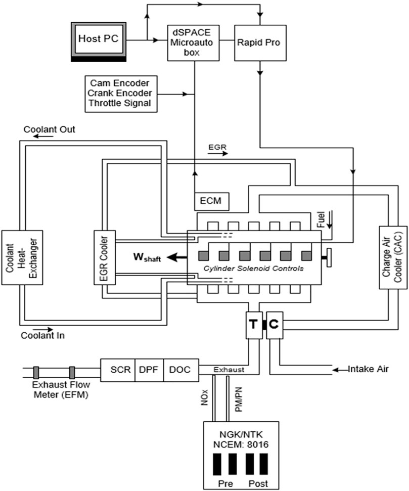
FIGURE 1. Engine instrumentation schematic.
Deactivation of individual cylinders was achieved by JVS patented hydraulic mechanism with minimum hardware changes to the base engine. The deactivation system comprised a modified rocker shaft as well as rocker arms and valve bridges. The hydraulic actuators used in this study (i.e., part of CDA hardware) are identical to the ones used as part of the JVS engine brake mechanism. Custom developed valve control mechanism was developed in MATLAB’s Simulink environment to evaluate the deactivation mechanism. A combination of dSPACE MicroAutoBox, and RapidPro was incorporated to implement the actuation model as part of the hardware in the loop (HIL) configuration. Activation of CDA controls for this study were based on engine speed and position i.e., derived based on signals broadcasted by cam and crank sensor, and throttle position acquired from the dynamometer controller. The deactivation algorithm has demonstrated the ability to implemented for both steady state and transient evaluation. To avoid increased oil consumption, the model was designed to deactivate the hydraulic mechanism on a periodic basis (i.e., configured as a function of revolution count).
Data presented in this paper consists of both steady-state firing tests and transient tests where CDA was active only during the motoring operation to reduce after treatment cool-down. Since the goal of implementation of CDA technology was targeted to improve exhaust gas thermal conditions under part load operations, particularly at low engine speed conditions. The targeted setpoints ranged from 800 to 1,200 rpm, with torque setpoint at 10 and 20% of rated torque as illustrated in Figure 2. Preliminary evaluation of CDA technology highlighted that the fuel required to meet the torque demand was exceeding the baseline fuel injection (i.e., total fueling) under load conditions at or above ∼25% of the rated torque. Thus, with three cylinders active, CDA could not be used above 25% rated torque without a fuel penalty. For the data presented in this study, steady state evaluation of CDA was examined only for 10 and 20% of rated torque.
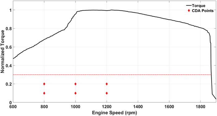
FIGURE 2. Torque curve with CDA test points.
A custom control calibration was developed with the objective of optimization of a limited number of available and accessible engine parameters that govern exhaust gas thermal conditions and BTE. Limited evaluation of the technology was performed which involved deactivation of the front three cylinders. Engine calibration was performed on two different modes of operating conditions i.e., fuel neutral and fuel economy modes. The “fuel neutral” calibration was aimed at targeting maximum exhaust temperature increase with no fuel penalty compared to the baseline fuel rate at the same speed and load. While the “fuel economy” calibration was aimed at lowering fuel consumption compared to baseline fuel rate, with sacrifices to the maximum achievable exhaust temperature increase during CDA operation. Provide consistency in comparison of results for each load point, steady state evaluation of engine calibrations involved a warm-up and cooling protocol i.e., data collection was initiated at SCR inlet temperatures of 130 and 160°C for 10 and 20% load. To account for engine stabilization and thermal gradience. The variation in engine torque at each setpoint was ± 2 N-m. Each calibration setpoint was evaluated for 180 s. Although the after treatment control was deactivated during the course of this study, the thermal response of the after treatment system substrate was examined to provide an understanding of the influence of the thermal inertia across the SCR system.
In addition to steady-state assessment of the technology under load, motoring cool-down curves were examined to understand the impact of rate of thermal cool down with the engine motored by the dynamometer as a function of number of deactivated engine cylinders. A custom test protocol was developed to ensure consistent starting point for evaluating after treatment cooldown during motoring operation with different levels of CDA active. The engine was set at a constant speed and load to warm the after treatment to 260°C. Once the SCR inlet was 260°C, the throttle was set to zero and engine speed was set to the appropriate motoring speed. If the test point required CDA active, the CDA hardware would be turned on when engine speed was changed. The effect of a cylinder deactivated motoring operation was also examined during transient test cycles under two different case scenarios: 1) Deactivation of three cylinders and 2) Deactivation of six cylinders. The evaluation was performed on a test sequence which included a cold-start FTP, a warm-start FTP, followed by the LLC, with a 20-min soak time between each test cycle. Exhaust gas thermal profiles were examined for the two test case scenarios mentioned above in comparison with test activity acquired from the baseline six-cylinder operation.
To understand the impact of cylinder deactivation in conjunction with engine control measures, steady-state engine calibration evaluation was performed under low-load conditions to examine the impact of a fuel neutral (FN) and improved fuel economy (FE) CDA approaches. A motoring test evaluated the effect of CDA on SCR inlet temperatures at two different engine speeds. The final evaluation examined the LLC temperature increase with CDA. For the results presented in this section, the engine was tested was at three different engine speeds of 800, 1,000, and 1,200 rpm and three different torque settings. The baseline fuel-rate was measured while the dyno was set to a certain engine speed and the torque was controlled by the throttle position. During CDA mode operation there will be a drop in engine torque due to the lesser work produced by the engine. In order to measure the appropriate fueling throttle setting was adjusted to bring the engine back to the target torque setpoint before measuring fuel rate.
An exception in meeting engine torque setpoint was observed for 20% rated torque for 800 and 1,000 rpm, where the engine calibration for FN and FE modes was unable to deliver the required torque during CDA mode to match the baseline torque setting. Therefore, a close to 10% decrease in brake power was observed at these two operating conditions. This lower brake power developed during CDA mode operation at 20% torque setting also led to a calculation of lower BTE for this operating condition.
Figure 3 provides a comparison overview of the baseline engine performance (i.e., six cylinders) along with performance characteristics of FN and a FE CDA strategy. In general, both the CDA calibration strategies depicted a significant increase in the turbocharger outlet temperature (TOT). At 10% and 20% engine load, the largest increase in TOT was observed from the FN approach, therefore resulting in an absolute increase of 103 and 117°C, respectively, compared to baseline six-cylinder operation. The SCR inlet temperature increase for the FN calibration was 23 and 35°C for 10 and 20% rated torque, respectively. The CDA strategies resulted in an exhaust energy rate reduction due to decrease in mass flow rate. Turbine outlet exhaust energy rate decreased ranging from 16 to 32% compared to the baseline engine at 800 rpm loads. At 10% rated torque, the FE strategy resulted in a higher exhaust energy rate compared to the FN strategy due to an increased mass flowrate even though there was a reduction in TOT. For all 800 rpm loads tested, SCR inlet exhaust energy rate decreased from 27 to 41% versus the baseline.
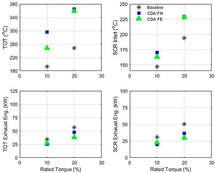
FIGURE 3. 800 rpm steady state exhaust parameters.
Figure 4 presents engine data during steady state testing at 800 rpm. At 10% rated torque, the FN calibration fueling decreased by 4.8% and the FE calibration decreased fueling by 10.7%. The FN fueling for 20% rated torque increased by 0.4% whereas the FE calibration fueling decreased by 1.6%. For 10% rated torque, BTE increased by 12.1 and 15.5% for the FN and FE calibrations, respectively. A reduction of approximately 5% in BTE occurred for CDA calibrations at the 20% rated torque points. Exhaust flow rate was expected to drop by ∼50% due to only three of the six cylinders being active during CDA. Steady state results showed a decrease in flowrate ranging from 30 to 45%. Recovery of exhaust flowrate was attainable due to optimization of the VGT. Baseline air-fuel ratio (AFR) was approximately 37:1 for both of the 10 and 20% rated torque points. The FN calibration resulted in an AFR of 23:1 for 10% rated torque and 24:1 for 20% rated torque. At 10% and 20% rated torque points, the FE calibrations AFR was 30:1 and 20:1, respectively. Similar trends for the 800 rpm, and low-load operations was observed by another study that employed a Cummins medium-duty engine with a different CDA hardware (Farrell, Koeberlein et al., 2018). During CDA operation the active cylinders are fueled more to maintain the same load as all six cylinders active. Therefore, the active cylinders during CDA are able to achieve a higher BTE due to improved mechanical efficiency. The overall improvement in mechanical efficiency lowers the brake-specific fuel consumption of the engine for the same load point.
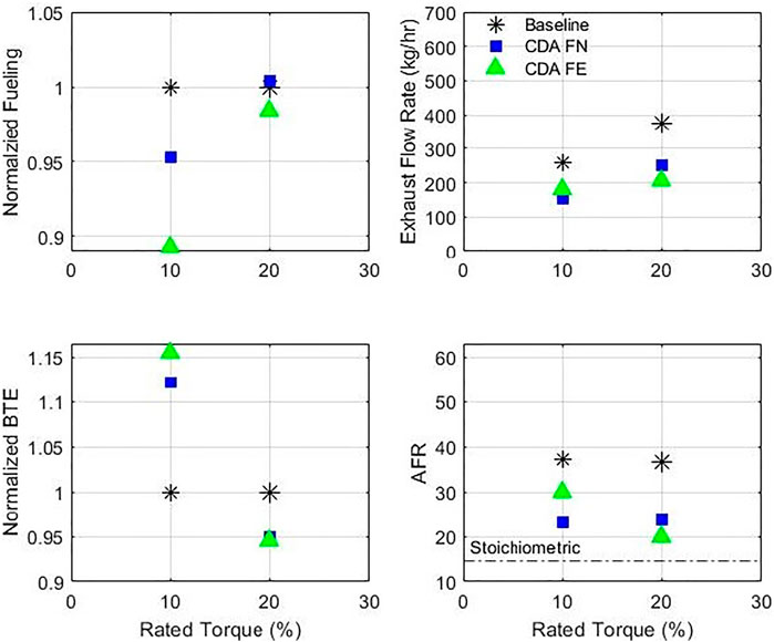
FIGURE 4. 800 rpm steady state engine data.
At 1,000 rpm, a similar performance evaluation as the 800-rpm operating point was conducted to examine the influence of thermal exhaust gas conditions and are presented in Figure 5. Consistent with the results obtained at 800 rpm, all TOT and SCR inlet temperatures increased during CDA test modes. Baseline TOT were 209°C for 10% rated torque and 245°C for 20% rated torque. At 10% rated torque, the FE calibration TOT was 253°C whereas the FN calibration was 292°C. For 20% rated torque, the FE test resulted in a TOT of 346 and 357°C for the FN calibration. The baseline SCR inlet temperatures were 155°C for 10% rated torque and 193°C for 20% rated torque. The FE calibration resulted in 173°C for 10% rated torque and 228°C for 20% rated torque. The SCR inlet temperature for the FN calibration was 188 and 233°C for 10 and 20% rated torque, respectively. Baseline turbine outlet exhaust energy rate was 49.5 kW for 10% rated torque and 63.4 kW for 20% rated torque operation. The decrease in mass flow rate of exhaust contributes to the overall decrease in exhaust energy flux across the after treatment system. However, the increased exhaust temperatures at a reduced energy flux will be sufficient to prevent cooling of the after treatment system in the short duration and over extended low-load operation could result in heating of the SCR after treatment system.
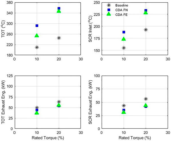
FIGURE 5. 1000 rpm steady state exhaust parameters.
In Figure 6, general engine parameters from the 1,000 rpm steady state tests are presented. For this engine speed, all CDA test points had a decrease in fueling compared to the baseline configuration. Fueling decreases ranged from 2.5 to 10.3%. Again at 10% rated torque, CDA resulted in the largest decrease in fueling. Following the same trend as 800 rpm, BTE increase with CDA for 10% rated torque and decreased at 20% rated torque. The 10% rated torque resulted in a 5.2% increase in BTE for the FN strategy and a 7.9% BTE increase for the FE calibration. At 20% rated torque, BTE decreased by 4.6% for the FN calibration and 3.8% for the FE calibration. Baseline exhaust flow rate was 360 kg/h at 10% rated torque and 426 kg/h at 20% rated torque. Employing both CDA strategies, exhaust flow rate decreased for all configurations ranging from 22 to 32%. The 1,000 rpm test points were able to reduce exhaust flow compared to the 800 rpm tests which exhaust flow was reduced by 30%–45%. Baseline AFR resulted in 10% rated torque being 39:1 and 33:1 for 20% rated torque. The FN calibration strategy showed an AFR of 30:1 for 10% rated torque and 22:1 for 20% rated torque. With the FE calibration, the AFR was 33:1 and 24:1 for 10% rated torque and 20% rated torque, respectively. For the 20% torque setting at both 800 and 1,000 rpm engine speeds, a lower BTE was calculated due to the inability of the engine to deliver the brake torque setting of CDA inactive mode. This is attributed to the engine not being able to deliver the required brake torque while operating on three-cylinder mode on the FN and FE calibration profiles. This shortcoming of CDA mode operation suggests the need for independent boost delivery mechanism using either an electrified turbocharger or supercharger-based system that can deliver the required boost requirements even with a reduced exhaust flow. Although the VGT is flexible in delivering a wide range of boost requirements for a six-cylinder operation, CDA mode pushes the limits of VGT operation while certain EGR rates are required. Turbocharger concepts like a SuperTurbo was used in another demonstration study to assist the primary turbocharger during CDA mode operation (Neely, Sharp et al., 2020). Furthermore, the separation of the EGR delivery mechanism from the turbocharger can also help expand the range of operation of the VGT. Use of electrical EGR pumps can be beneficial during CDA mode operation with the turbocharger working only to deliver the required boost (Bagal and Bhardwaj 2022).
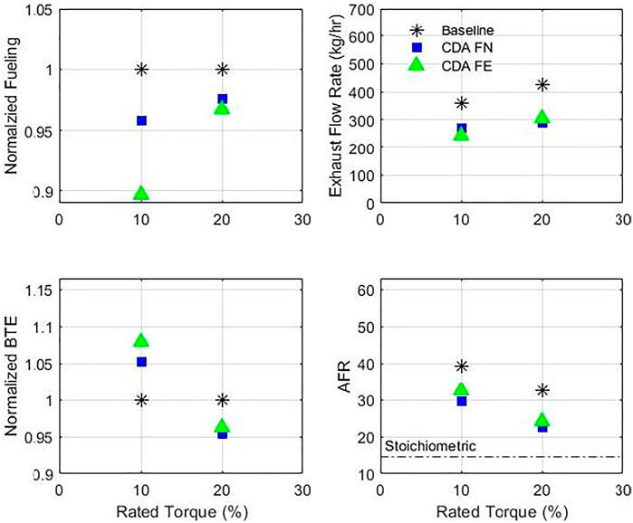
FIGURE 6. 1000 rpm steady state engine data.
Steady state 1,200 rpm testing, presented in Figure 7 and Figure 8, resulted in the least effective test points for three-cylinder CDA. Exhaust temperatures were the only parameters that followed similar trends when compared to the other tested engine speeds. Baseline TOT was 185°C at 10% rated torque and 236°C at 20% rated torque. The FN calibration increased TOT by 106 and 117°C for 10 and 20% rated torque, respectively. The FE strategy increased TOT by 77°C at 10% rated torque and 116°C at 20% rated torque. Baseline SCR inlet temperature was 156°C at 10% rated torque. The CDA FN calibration resulted in 204 and 186°C for the FE configuration at the 10% rated load condition. At 20% rated torque, baseline SCR inlet temperature was 195°C. The FN calibration demonstrated an SCR inlet of 246°C and the FE calibration was 243°C for 20% rated torque. Turbine outlet exhaust energy rate for the baseline testing was 85.8 kW at 10% rated torque and 85.2 kW at 20% rated torque. For 10% rated torque, the FN strategy decreased the exhaust energy rate by 36% whereas the FE calibration decreased the exhaust energy rate by 44%. The FN calibration decreased the exhaust energy rate by 16% at 20% rated torque whereas the FE calibration exhaust energy rate was reduced by 18%. The SCR inlet energy rate followed the same trend with a reduction of 43% occurring with the FN calibration at 10% rated toque with the FE calibration reduction being 49%. At 20% rated torque, the FN calibration SCR inlet energy rate was reduced by 26% and a 28% decrease for the FE calibration.
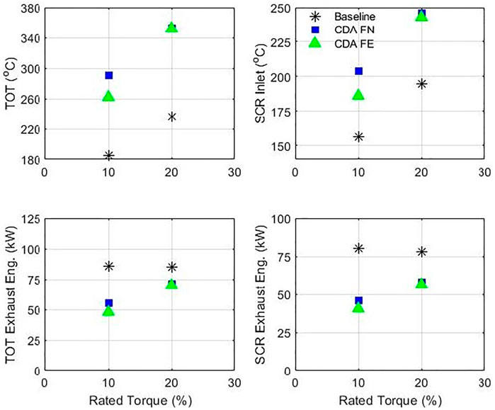
FIGURE 7. 1200 rpm steady state exhaust parameters.
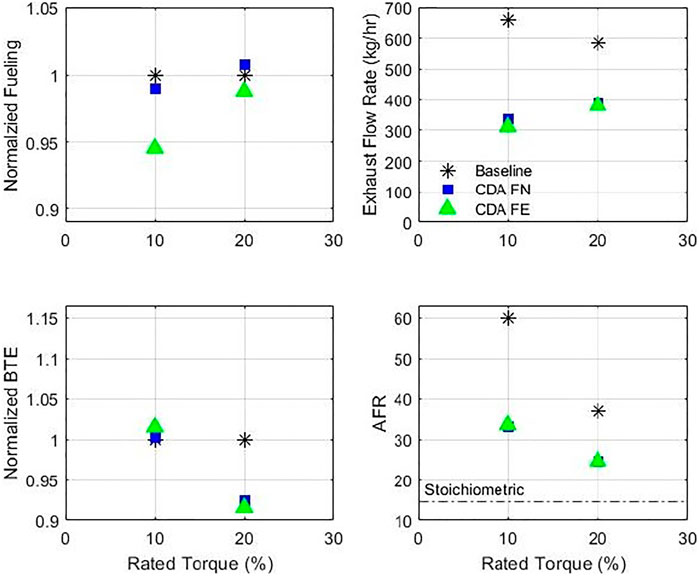
FIGURE 8. 1200 rpm steady state engine data.
Figure 10 presents the engine parameters measured during 1,200 rpm steady state testing. Fueling decreased by 1.0% at 10% rated torque and increased by 0.8% for the FN CDA strategy. Steady state FE calibration results had a fuel rate decrease of 5.5 and 1.2% for 10 and 20% rated torque, respectively. Like all other test configurations, BTE increased for 10% rated torque and decreased for 20% rated torque. The FN calibration increased BTE by 0.2% at 10% rated torque and decreased by 7.5% at 20% rated torque. The FE calibration increased BTE by 1.5% and decreased BTE by 8.4% at 10 and 20% rated torque, respectively. Baseline exhaust flow rate was 659 kg/h at 10% rated torque and 584 kg/h at 20% rated torque. The FN calibration had higher exhaust flow rates for both loads compared to the FE calibration. With CDA active, exhaust flow rate ranged from 311 kg/h up to 388 kg/h. At 10% rated torque, the FN calibration exhaust flow rate decreased by 49% and the FE calibration exhaust flow rate decreased by 53%. The 20% rated torque CDA testing had an exhaust flow rate decrease of 34 and 35% for the FN and FE calibrations, respectively. The AFR for baseline testing was 60:1 at 10% rated torque and 37:1 at 20% rated torque. For 10% rated torque, the CDA strategy AFR’s were approximately 33:1 while at 20% rated torque, the AFR’s were approximately 25:1.
The influence of heat transfer on exhaust gas temperature was examined during motoring segments across two different engine speeds i.e., 800 and 1,500 rpm. The impact was analyzed by individually deactivating one to three cylinders. Since exhaust mass flow is dependent on engine speed and total displacement of the engine, deactivation of individual cylinders resulted in a decreased mass flow; therefore, a delay in the decay of the exhaust gas temperature at the SCR catalyst inlet was observed. At all engine speeds, deactivation of three cylinders resulted in a delay of the cooling of the exhaust gas in comparison to the baseline six-cylinder motoring engine operation. An SCR inlet temperature of 170°C was chosen as the threshold for data collection to stop. The results illustrate a strategy involving the deactivation of cylinders during extended down-hill operation can significantly reduce after treatment cooling and therefore prevent high-NOx emissions during the return-to-service event at the end of the motoring operation.
Figure 9 shows motoring cooling results for an engine speed of 800 rpm. The temperature traces shown are when the fueling for each test configuration was set to zero until the SCR inlet temperature was below 170°C. Peak temperatures varied from test to test due to the inability to exactly repeat engine thermal history as well as CDA configuration. Baseline motoring took 89 s to reach 260°C, one-cylinder CDA was 114 s, two-cylinder CDA required 148 s and three-cylinder CDA took 204 s. The total motoring cool down time was: 256 s for the baseline, 299 s for one-cylinder CDA, 355 for two cylinders CDA, and 436 s for three cylinders CDA. Implementation of CDA resulted in 16.8, 38.7, 70.3% longer duration of the SCR temperature being above 170°C for one, two, and three CDA, respectively, at 800 rpm.
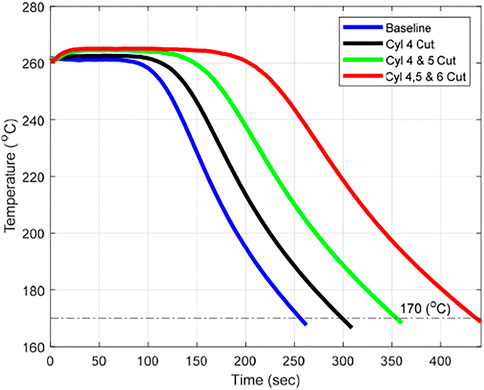
FIGURE 9. 800 rpm SCR inlet motoring cool down.
Figure 10 presents 1,500 rpm motoring cool down data. Baseline cool down time was 125 s from fuel cut to SCR inlet of 170°C. For one cylinder cut, cool down time was 152 s, two cylinders cut resulted in 189 s and three cylinder cut was 247 s. At 1,500 rpm, three cylinder cut resulted in approximately doubling the time to cool the SCR inlet exhaust versus the baseline engine cooling. Implementation of CDA resulted in 21.6, 51.2, 97.6% longer duration of the SCR temperature being above 170°C for one, two, and three CDA, respectively, at 1,500 rpm.
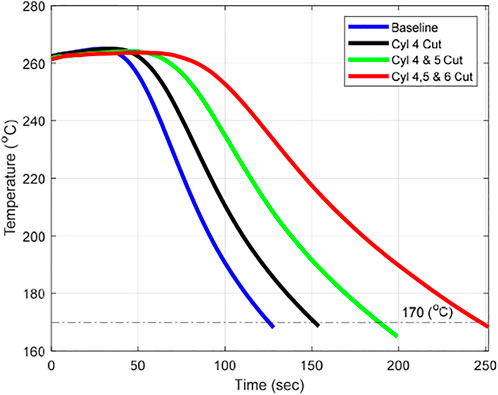
FIGURE 10. 1500 rpm SCR inlet motoring cool down.
The effect of motoring CDA operation during a transient test cycle such as FTP (i.e., both on cold and hot start conditions) and LLC was examined. In order to understand the influence of thermal energy differences, CDA was active only during motoring segments of the test cycle. Figure 11 presents a comparison of exhaust gas thermal profiles for baseline operation, active CDA i.e., three and six cylinders, respectively, during motoring segments of the LLC test cycle. In order to attain thermal stabilization of the aftertreatment system, a preconditioning FTP cycle along with a 20-min soak time was part of the warm-up sequence prior to data acquisition of the test dataset. The overall test sequence was: cold start FTP followed by a 20-min soak, followed by a hot start FTP, followed by a 20-min soak, followed by a hot start LLC. The FTP cycles were used to condition the engine and after treatment systems; only the LLC data is presented here.
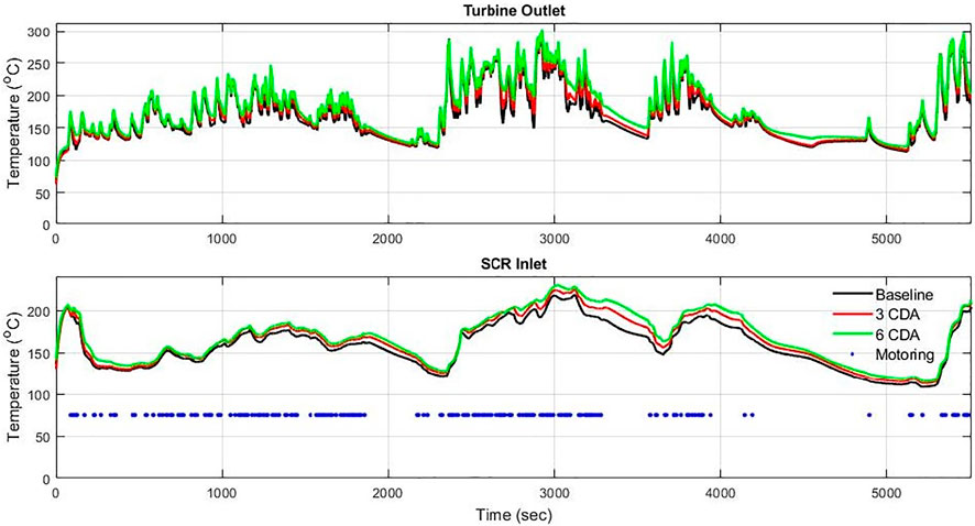
FIGURE 11. CARB LLC exhaust temperature profile.
The total duration of a LLC is 5,505 s with 15% of the cycle consisting of motoring operation. Idle time is also significant during the LLC and accounts for approximately 39% of the test cycle. The TOT and SCR inlet exhaust profiles for the LLC are presented in Figure 11. On the SCR inlet plot, motoring instances are displayed as the blue dots. The initial baseline SCR inlet temperature was 137°C, three CDA was 131°C and six CDA was 142°C. End of cycle SCR inlet temperature was 204°C for the baseline, 210°C for three CDA and 213°C for six CDA. The maximum SCR inlet temperature for baseline test was 219°C, 225°C for three CDA and 231°C for six CDA. Over the whole cycle, the baseline average SCR temperature was 159°C with a total time of 284 s above 200°C. For the three CDA test, the average SCR temperature was 165°C with 707 s above 200°C. The average SCR inlet temperature was 169°C for the six CDA configuration with the SCR inlet being above 200°C for 1,104 s. CDA active tests saw significant increases in the duration of engine operation where temperatures at the inlet of SCR was above 200°C, which is indicative of a longer duration of SCR activity and consequently lower NOx emissions during the LLC. A 149% increase in time above 200°C for three CDA and a 289% increase for six CDA configuration was observed.
There are three segments where CDA had sustained temperature effects while motoring: 1,200–2,350 s, 2,730–3,680 s, and 3,870–4,490 s. The first segment resulted in an average TOT of 156°C for the baseline, 160°C for three CDA, and 164°C for six CDA. Similarly, the SCR inlet average was 155°C for the baseline, 161°C for three CDA and 164°C for six CDA. For the second segment, the baseline average SCR inlet was 186°C and average TOT was 191°C. The three CDA test configuration resulted in an average SCR inlet and TOT of 199°C. For the six CDA test, the average SCR inlet was 206°C and the average TOT was 210°C. The baseline SCR inlet time above 200°C was 249 s, whereas the three CDA and six CDA test configurations were 550 and 725 s, respectively. The final segment had an average SCR inlet of 168°C for the baseline, 176°C for three CDA and 182°C for six CDA. The TOT average was 153°C for the baseline, 156 and 163°C for three CDA and six CDA test configurations, respectively. The baseline test never exceeded an SCR inlet of 200°C whereas the three CDA test was above 200°C for 59 s and the six CDA tests had an SCR inlet exceed 200°C for 171 s of the segment. The result of the transient test shows the ability of a CDA technology to prevent after treatment cool down during motoring operation. Since the study did not include any transient calibrations on the engine fuel consumption difference between CDA active and inactive cannot be presented. However, employing CDA during motoring operation could prevent cool down of the SCR below its activation temperature and prevent the engine management from employing a thermal management strategy that could potentially lead to a fuel penalty. Therefore, a combination of CDA during motoring and CDA during low-load firing operation can help maintain sustained SCR temperatures for improved tailpipe NOx reductions.
Steady state results of engine operation with CDA active showed an average 13% increase in BTE at engine speeds of 800 and 1,000 rpm with torque set at 10% of rated torque. While a fuel neutral operation was observed at 1,200 rpm and 10% of peak torque. A 5% drop in BTE was observed at 1,200 rpm and 20% rated torque and fuel neutral operation was observed for same torque at 800 and 1,000 rpm. The steady state results show that CDA is viable solution for fuel neutral and fuel-efficient thermal management strategy at low-load operations. Vocations such as urban delivery and port drayage exhibit significant duration of idling and stop-and-go type driving conditions. Results from this study show that CDA operation can result in significant increase in TOT with no fuel penalty. Further calibration and optimization of engine operation during CDA operation can improve TOT temperatures while still maintaining a zero-fuel penalty. With limited calibration resources available for the engine during this campaign, a complete optimization of multiple engine parameters was not performed. Furthermore, the CDA in this study was not tested on transient cycles due to the inability to perform transient engine calibration. In addition to increasing TOT temperatures during engine firing operation, CDA can be used as an approach to reduce the rate of cooling of the after treatment system during motoring operation. Disabling banks of cylinders reduces the air pumping action of those cylinders and thereby reducing the mass air flow of air across the after treatment system. Overall, this study shows an overall improvement to engine BTE and TOT during CDA operation is possible. To further quantify CDA operation, additional developmental processes such as hardware durability, modes of failure, thresholds of operation, torsional vibration and interaction of other engine parameters such as EGR delivery and boost pressure needs a comprehensive evaluation. Development of a comprehensive control strategy that considers conditions that result in oil entrainment into the cylinder is also a critical requirement. Finally, some key changes to the base engine architecture are desired for expanding the domain of operation of CDA mode. Specifically, engine technologies to provide the required boost and a wide range of EGR rates, independent of turbo operation is critical to develop a successful control strategy for CDA operation.
The datasets presented in this article are not readily available because Data are proprietary engine information sealed by an NDA with the engine manufacturer. Requests to access the datasets should be directed to dHBhcnZpbmRAZ21haWwuY29t.
AT was the principal investigator for the research project and was responsible for developing the research work, executing the project, and managing graduate students and technicians during project execution. CH was the graduate student who executed the study and completed his master’s degree as part of this research project. CH was responsible for all the data-gathering activity. RP was a Ph.D. student who assisted CH with data analysis and performed combustion analysis. GT was responsible for the quality control of the collected data and was a critical technical point of contact during the project execution. GT was also integral to the development of this manuscript. JB and RJ from JVS were the key technical point of contact from Jacobs Vehicle System who was instrumental in designing and developing the CDA hardware. They both were involved in the development of the test matrix and the evaluation of the collected data. JL and LF were key technical points of contact from Cummins Inc. They were integral to the engine and CDA hardware integration as well as the integration of the Hardware-in-loop (HIL) system with the test engine.
This study was received from Environmental Climate Change Canada and South Coast Air Quality Management District. Both funding agencies awarded funds execute the research work as well as fund graduate students.
LF and JL were employed by the company Cummins Inc, and RJ and JB were employed by Jacobs Vehicle Systems.
The remaining authors declare that the research was conducted in the absence of any commercial or financial relationships that could be construed as a potential conflict of interest.
All claims expressed in this article are solely those of the authors and do not necessarily represent those of their affiliated organizations, or those of the publisher, the editors and the reviewers. Any product that may be evaluated in this article, or claim that may be made by its manufacturer, is not guaranteed or endorsed by the publisher.
Archer, A., and McCarthy, J. (2018). Quantification of diesel engine vibration using cylinder deactivation for exhaust temperature management and recipe for implementation in commercial vehicles. SAE Int. doi:10.4271/2018-01-1284
Bagal, N. L., and Bhardwaj, D. (2022). 48V EGR pump system development and fuel benefit evaluation. Front. Mech. Eng., 8. doi:10.3389/fmech.2022.673134
Boriboonsomsin, K., Durbin, T., Scora, G., Johnson, K., Sandez, D., Vu, A., et al. (2018). Real-world exhaust temperature profiles of on-road heavy-duty diesel vehicles equipped with selective catalytic reduction. Sci. Total Environ. 634, 909–921. doi:10.1016/j.scitotenv.2018.03.362
CARB (2019). California air resources board staff current assesment of the technical feasibility of lower NOx standards and associated test procedures for 2022 and subsequent model year medium-duty and heavy-duty diesel engines.
Ding, C., Roberts, L., Fain, D. J., Ramesh, A. K., Shaver, G. M., McCarthy, J., et al. (2016). Fuel efficient exhaust thermal management for compression ignition engines during idle via cylinder deactivation and flexible valve actuation. Int. J. Engine Res. 17 (6), 619–630. doi:10.1177/1468087415597413
Farrell, L., Koeberlein, E. D., Ramesh, A. K., Gosala, D. B., Allen, C., Joshi, M., et al. (2018). Cylinder deactivation for increased engine efficiency and aftertreatment thermal management in diesel engines. SAE Int.
Joshi, M. C., Gosala, D. B., Allen, C. M., Vos, K., Van Voorhis, M., Taylor, A., et al. (2017). Reducing diesel engine drive cycle fuel consumption through use of cylinder deactivation to maintain aftertreatment component temperature during idle and low load operating conditions. Front. Mech. Eng. 3 (8). doi:10.3389/fmech.2017.00008
JVS (2020). Cylinder deactivation. Available at: https://www.jacobsvehiclesystems.com/technologies/cylinder-deactivation.
Matheaus, A., Evans, D., Sanchez, L., Singh, J., and Janak, R. (2020). Evaluation of cylinder deactivation on a class 8 truck over light load cycles. SAE Int. doi:10.4271/2020-01-0800
Neely, G. D., Sharp, C., and Rao, S. (2020). CARB low NOx stage 3 program - modified engine calibration and hardware evaluations. SAE Int. doi:10.4271/2020-01-0318
Quiros, D. C., Thiruvengadam, A., Pradhan, S., Besch, M., Thiruvengadam, P., Demirgok, B., et al. (2016). Real-World emissions from modern heavy-duty diesel, natural gas, and hybrid diesel trucks operating along major California freight corridors. Emiss. Control Sci. Technol. 2 (3), 156–172. doi:10.1007/s40825-016-0044-0
Thiruvengadam, A., Besch, M., Thiruvengadam, P., Pradhan, S., Carder, D., Kappanna, H., et al. (2015). Emission rates of regulated pollutants from current technology heavy-duty diesel and natural gas goods movement vehicles. Environ. Sci. Technol. 49, 5236–5244. doi:10.1021/acs.est.5b00943
USEPA (2011). Final rulemaking to establish Greenhouse gas emissions standards and fuel efficiency standards for medium- and heavy-duty engines and vehicles. Washington, D. C: OTAAQ.
Keywords: heavy-duty diesel engines, cylinder deactivation (CDA), thermal management, selective catalytic reduction, low-load operation
Citation: Hushion C, Thiruvengadam A, Pondicherry R, Thompson G, Baltrucki J, Janak R, Lee J and Farrell L (2022) Investigating cylinder deactivation as a low fuel-penalty thermal management strategy for heavy-duty diesel engines. Front. Mech. Eng 8:987170. doi: 10.3389/fmech.2022.987170
Received: 05 July 2022; Accepted: 06 September 2022;
Published: 06 October 2022.
Edited by:
Evangelos G. Giakoumis, National Technical University of Athens, GreeceReviewed by:
Jaime Martín, Universitat Politècnica de València, SpainCopyright © 2022 Hushion, Thiruvengadam, Pondicherry, Thompson, Baltrucki, Janak, Lee and Farrell. This is an open-access article distributed under the terms of the Creative Commons Attribution License (CC BY). The use, distribution or reproduction in other forums is permitted, provided the original author(s) and the copyright owner(s) are credited and that the original publication in this journal is cited, in accordance with accepted academic practice. No use, distribution or reproduction is permitted which does not comply with these terms.
*Correspondence: Arvind Thiruvengadam, YXJ2aW5kLnRoaXJ1dmVuZ2FkYW1AbWFpbC53dnUuZWR1
Disclaimer: All claims expressed in this article are solely those of the authors and do not necessarily represent those of their affiliated organizations, or those of the publisher, the editors and the reviewers. Any product that may be evaluated in this article or claim that may be made by its manufacturer is not guaranteed or endorsed by the publisher.
Research integrity at Frontiers
Learn more about the work of our research integrity team to safeguard the quality of each article we publish.