 Zihao Su
 Yifan Zhu
 Siyuan Gao
 Hui Zhang
- Jiangsu Key Laboratory for Design and Manufacture of Micro-Nano Biomedical Instruments, School of Mechanical Engineering, Southeast University, Nanjing, China
Acoustic insulation in ventilated structures is an important problem in acoustic engineering with many potential practical applications, such as the noise control for ventilating ducts of buildings, vehicles, or air conditioners. Acoustic metamaterial is a good candidate for the design of acoustic insulation for ventilated channel (AIVC) because the structural design with hard boundary has longer lifetime than conventional sound-absorbing cotton. In this paper, an AIVC with an open region and narrow channels of different lengths is proposed. We numerically and experimentally demonstrate its acoustic insulation larger than 20 dB (T < 0.01) within approximately 500–1,200 Hz with a subwavelength channel length of λ/6. The parameter dependence and air flow effect are numerically studied. Our findings show an alternative design of AIVC that may have applications in noise control and architectural acoustics.
Introduction
In acoustic engineering, it is a key scientific problem to achieve low frequency and broadband noise control by sound absorptions or sound insulations. In the past decades, acoustic metamaterials (Cummer et al., 2016; Ma and Sheng, 2016)and acoustic metasurfaces (Assouar et al., 2018) have become the most promising candidates for noise control engineering and advanced acoustic material design and manufacture, due to their physical characteristics, shape controllability and small volume/size. Acoustic metamaterial/metasurface-based absorbers have been designed for ultra-broadband working bandwidth (Jiang et al., 2014; Yang et al., 2017; Zhu et al., 2019; Huang et al., 2020; Kumar and Lee, 2020; Zhu et al., 2021), ultra-light mass (Yang et al., 2008; Yang et al., 2010; Yao et al., 2010; Mei et al., 2012; Fan et al., 2015; Huang et al., 2016; Gao et al., 2017; Gao et al., 2018; Li et al., 2020; Zhang et al., 2020) and ultrathin sample thickness (Li and Assouar, 2016; Donda et al., 2019; Donda et al., 2021), which benefit the development of conceptual acoustic device called acoustic meta-absorber.
Acoustic absorption (Li et al., 2018; Wu et al., 2018) and insulation (Yang et al., 2018) by acoustic metamaterials in ventilated structures is another important problem in acoustic engineering with many potential practical applications, such as the noise control for the ventilating ducts of buildings, vehicles, or air conditioners. In previous works, acoustic insulation ventilated channels (AIVC) have been designed with the help of acoustic metamaterials (Zhang et al., 2017; Lee et al., 2019; Sun et al., 2020; Dong et al., 2021; Shen et al., 2021). Considering the tradeoff between sample size and working efficiency, previous balanced designs always have an average absorption within approximately 0.85–0.95 (Jiang et al., 2014; Yang et al., 2017; Zhang et al., 2017; Lee et al., 2019; Zhu et al., 2019; Huang et al., 2020; Dong et al., 2021; Shen et al., 2021; Zhu et al., 2021). However, high-efficient sound insulation is very important and significant for acoustic engineering applications. A high sound insulation index (close to 1) is highly desirable for many practical cases when the intensity of noise source is very large, such as the noises from construction sites or large-scale vehicles.
In this paper, an AIVC with an open region and narrow channels of different lengths is proposed. We numerically and experimentally demonstrate its acoustic insulation larger than 20 dB (meaning sound intensity transmission T < 0.01) within approximately 500–1,200 Hz with a subwavelength channel length of λ/6. This high transmission loss is very important in many practical sound insulation occasions. We have designed the channel lengths with different distributions, such as the linear one and the optimized one. More parameter dependence of the AIVC is studied, such as the different open region widths from 15 to 40 mm, and different narrow channel widths from 6 to 9 mm. Our findings show an alternative design for perfect sound insulation with a high sound reduction index, that may have applications in environmental acoustics and architectural acoustics.
Design Method
The method reported in this paper enables the design of open-type acoustic metamaterials consisting of narrow Fabry-Pérot (FP) channels (Jiang et al., 2014; Yang et al., 2017; Xiao et al., 2021) with open region that provide high sound attenuation and adequate ventilation performance. Inspired by previous work (Deng et al., 2017; Ghaffarivardavagh et al., 2019; Shi et al., 2021), the FP channels are used as a side branch, which greatly improve the sound insulation performance of the structure, while retaining the opening part to ensure its ventilation performance. The schematic diagram of the designed AIVC is shown in Figure 1. The parameters are marked in the figure. For an original design, the total length of AIVC is l = 120 mm. The diameter of open region W = 20 mm, the width of FP channels d = 7 mm, the difference between the lengths of adjacent numbered channels is n, n = 8 mm for the original design. t is the interval between channels and the sum of d and t is a constant value. As shown in Figure 1A, the sound wave passes through the open region with the periodically arranged side branches, the walls of the side branches can be assumed to be rigid, and the medium in the channels is air. Distributing the narrow tubes on both sides not only saves space, but also enhances coupling and improves sound insulation performance. The incident acoustic wave will be coupled with different FP channels and dissipated inside. In Figure 1B, the length of the channels varies linearly (relative to the number i). The number i annotated in Figure 1B from 1 to 12 denotes the cells with first-order peak frequency from lower to higher. It is noted that Figure 1B shows a periodic arrangement (1–11 and 1′-11′) which is an original design but not necessary in our work. We will show other non-periodic designs in the following.
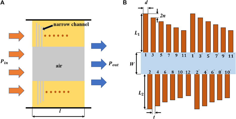
FIGURE 1. (A) The schematic diagram of the ventilation and sound insulation of AIVC. The total length of AIVC l = 120 mm. (B) The two-dimensional structure diagram of the designed AIVC, the diameter of open region W = 20 mm, the width of FP channels d = 7 mm, and the difference between the lengths of adjacent numbered channels is n, n = 8 mm for the original design,
The first-order resonance frequency is determined by the length of the FP resonance channel, and their relationship can be described as
where
where
Numerical Simulations
To verify the sound insulation effect of the structure, numerical simulations have been performed by the commercial finite element software COMSOL. The Viscous effect has been considered in the simulations in the Thermoviscous Acoustics Module and the results are shown in Figure 2. To understand completely the mechanism of the broadband acoustic insulation, Figure 2A shows the sound transmission loss (STL) curves for a single resonator, two coupled resonators with slightly different lengths, and 12 coupled resonators, respectively. The results suggest that the coupling of the unit cells leads to the connection of STL spectrum. From Figure 2B, an ultra-broadband sound isolation of more than 20 dB can be observed, approximately from 520 to 1,280 Hz, over an octave. The sound transmission loss band consists of 12 peaks, which correspond to 12 FP resonant channels of different lengths. The lengths of the channels and their corresponding resonant frequencies calculated by Eq. 1 are shown in Figure 2C.
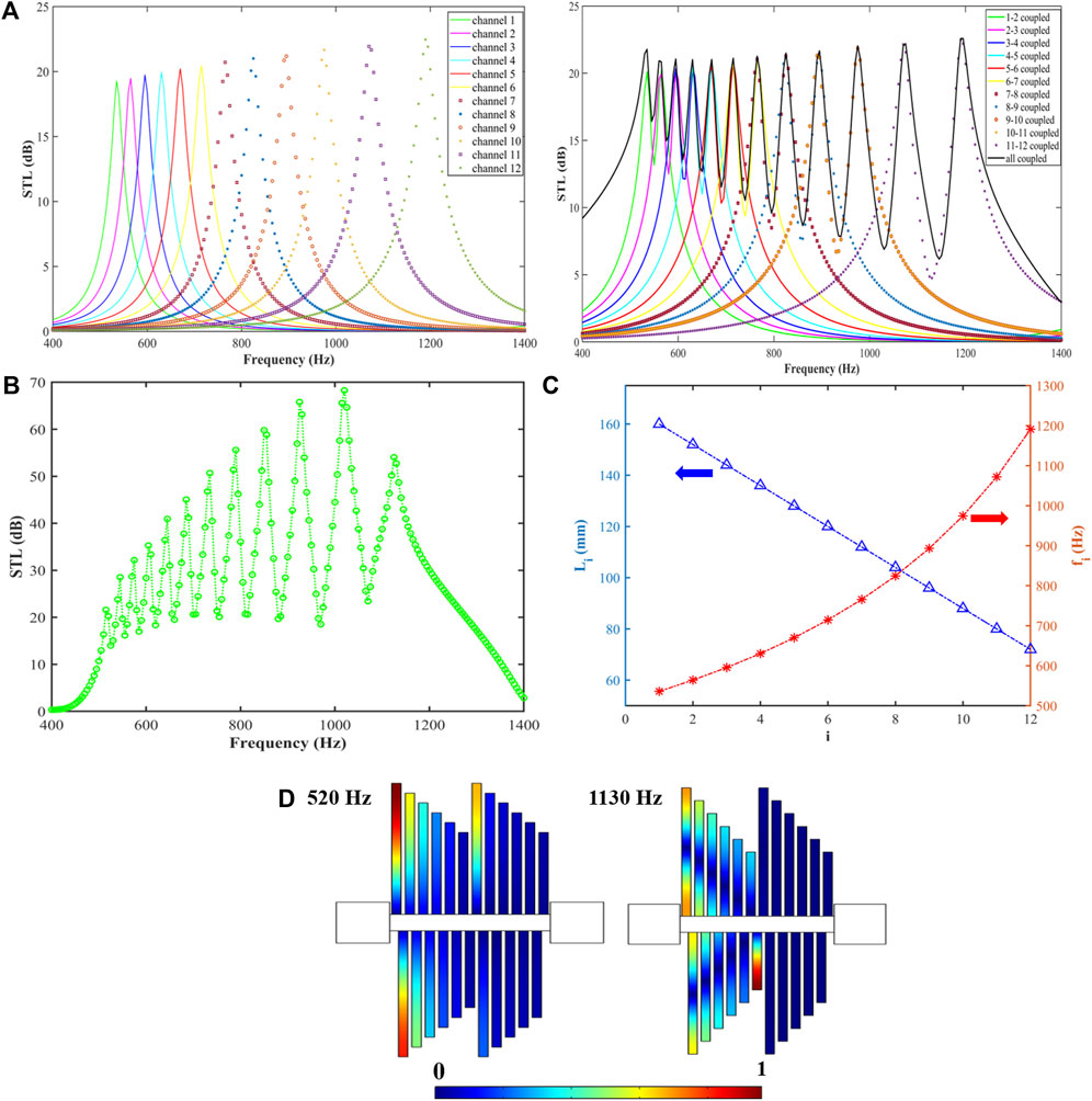
FIGURE 2. (A) Resonance characteristics of single resonator, 2 coupled resonators and 12 coupled resonators. (B) Simulation curve of sound transmission loss. (C) The length of and the first-order resonant frequency of the channels calculated by Eq. 1. (D) Simulated sound field distribution at 520 and 1,130 Hz.
By comparing Figures 2B,C, it can be clearly seen that the resonant frequency at the peak of the sound transmission loss band is observed not exactly at the resonant frequency of the single resonant channel, owing to the coupling effects of the whole structure. To further explain this phenomenon, Figure 2D shows the simulated acoustic pressure amplitude field at 520 and 1,130 Hz, respectively. These two frequencies correspond to the first and 12th (last) peaks, respectively. Different from the traditional FP resonance channels, the staggered arrangement makes the FP resonance channels no longer act individually, but the adjacent numbered channels act simultaneously, thus resulting in the shift of the peak frequency to low frequency. As can be seen in Figure 2D, at 520 Hz, the dominant channels are 1, 2 and 1′, not just 1 and 1′. After passing through the 1′ channel, there is no high sound pressure distribution in the rear channels, which proves the effectiveness of the sound insulation of the structure. The same effect can also be observed in the sound field distribution diagram at 1,130 Hz. A higher sound pressure appears in the 12th channel, which blocks the sound from propagating backwards, so a lower sound pressure distribution appears in the rear channels.
To further improve the performance of the structure, the channel length and distribution were changed from linear to nonlinear, and the symmetry is changed for the bottom narrow channels, as shown in Figure 3. The sound insulation performance has dropped slightly, for which some valley values are below 20 dB. Interestingly, the STL bandwidth covers the frequency range from 490 to 1,330 Hz. Compared to the design in Figure 2, the bandwidth for sound insulation is increased, due to the fact that the resonant absorption frequencies are optimized, and the change of the symmetry for bottom narrow channels can alter the coupling effects between adjacent unit cells.
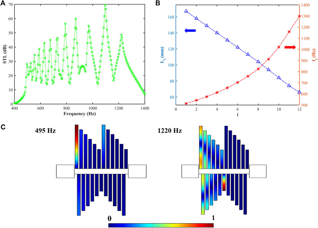
FIGURE 3. (A) Simulation curve of sound transmission loss. (B) The length of and the first-order resonant frequency of the channels calculated by Eq. 1. (C) Simulated sound field distribution at 495 and 1,220 Hz.
Parameter Dependences and Air Flow Effect
We further investigated the dependence of the sound insulation effect on the diameter of the open region and the FP resonant channel width. In practice, there should be reasonable structural dimensions while maintaining the performance of sound insulation.
Figure 4A shows the sound transmission loss of AIVC as a function of frequency with different d values from 6 to 9 mm. The simulation results prove that the broadband characteristics of AIVC are hardly affected by the variation of channel width, and the apparent difference only appears at the peaks as shown in the inset of Figure 4A. The larger d value has higher sound insulation because of the better coupling at the opening of the narrow channel. The changing the diameter of the FP resonant channel will only affect the performance at the peak frequency, and has little effect on the bandwidth and performance at other frequencies.
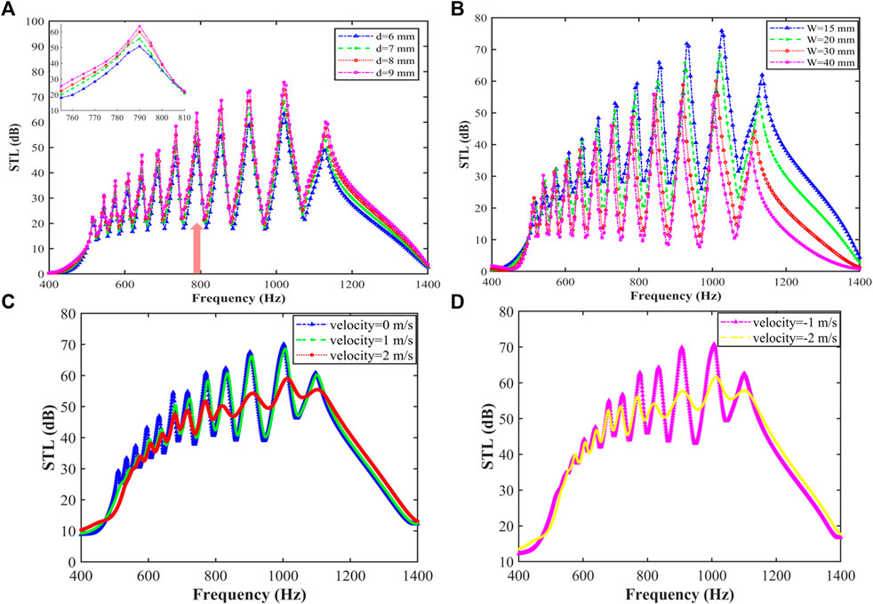
FIGURE 4. (A) Sound transmission loss of different side branch width d. The inset shows the zoom-in curves. (B) Sound transmission loss for different open region diameters W. (C) Sound transmission loss for different airflow velocity for positive direction with v ≥ 0 (D) Sound transmission loss for different airflow velocity for negative direction v < 0.
Figure 4B shows the sound transmission loss curves with different open region widths. The four curves correspond to four different open region widths of 15 mm, 20 mm, 30 mm and 40 mm, respectively. It can be observed that as the open region width is significantly reduced, the acoustic transmission is effectively suppressed, and at the same time, an improvement in performance over the entire frequency band is achieved. This result indicates that there is a tradeoff between the ventilated area and sound insulation efficiency.
We also study the influence of air flow effects in the ventilated channel for sound insulation. Aeroacoustics Module of the COMSOL software is used to study the air flow effect in AIVC. The corresponding simulated results are shown in Figures 4C,D with positive and negative airflows, respectively. The results show that the airflow effect has an obvious influence on sound insulation. When the velocity of the medium v (background mean flow velocity) is 0 m/s, the STL curve is in high agreement with Figure 2B. As the medium velocity increases, the peaks at low frequencies and the sound insulation decreases slightly.
Experiment Demonstration of a 3D Design
In order to experimentally verify the performance of AIVC in terms of sound insulation, an experimental sample is fabricated via a 3D printing technique in Figure 5. As shown in Figure 5A, the sample is designed as a ventilation structure with folded channels and a circular cross section (diameter = 10 cm) whose size agrees with standard acoustic impedance tube. We use folded channels in 3D case to replace straight channels in 2D case for the convenience of sample fabrications and experimental demonstration. The centre portion of the designed structure is a completely open region which yields a high degree of airflow. To be consistent with the 3D simulation, we fabricated the sample with PLA as the 3D printing material, which can be regarded as a hard boundary. The arrangement of the side branches is the same as in Figure 2, and the structure size is slightly changed, where d = 8.75 mm, t = 3.75 mm, l = 150 mm,
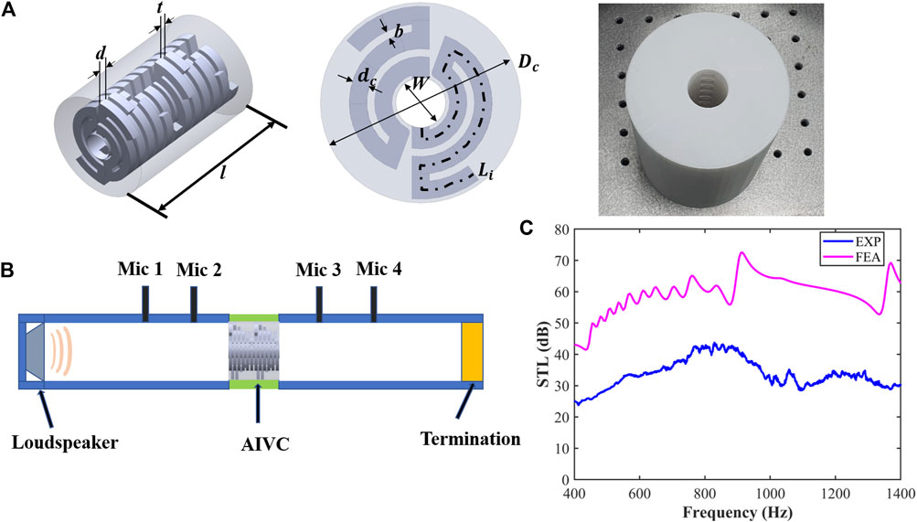
FIGURE 5. (A) AIVC isometric 3D schematic diagram (left), front view (middle), and the photograph of sample (right). (B) Schematic of the experimental setup. (C) Comparison between the numerical and experimental results of the sound transmission loss.
The experimental setup is shown in Figure 5B. The four microphones method is adopted to measure the transmission loss of the AIVC. A loudspeaker is placed at one end of the impedance tube. Termination is set as sound absorption termination for sound insulation measurement. The sample is placed in the middle.
The experimental results are shown in Figure 5C. The numerical (experimental) STL for sound insulation is large than 40 dB (25 dB) within 400–1,400 Hz, and the averaged STL in this band is approximately 55 dB (35 dB). The sound insulation effect for 3D design is better than 2D ones. This is probably because the 3D one makes full use of the space, and the coupled effect between unit cells for 3D case is better. The difference between numerical and experimental STL is approximately 20 dB. This value difference seems to be large with exponential units (dB), but the STL of both exceeds 20 dB, which means that more than 99% of the sound energy is blocked. So the experimental one has a high-efficient insulation as well as the numerical one. The averaged error between numerical and experimental ones is less than 0.06, which may be due to the imperfect of sample fabrications and slight leakage of sound.
Conclusion
In summary, we have theoretically demonstrated a broadband low-frequency soundproof ventilation channel with a structural thickness of only 120 mm (about λ/6), which can effectively block more than 99% of the incident sound energy in the range of about 500–1,200 Hz and have experimentally verified our proposal. The ventilation channel consists of a central open region and 12 kinds of side branches consisting of different length narrow channels. By adjusting the distribution of side branch channels, high sound insulation performance is achieved, and the simulation and experimental results successfully verified our theory. At the same time, we also considered the influence of the width of the opening region, the width of the side branch channel and air flow effect (including flow speed and direction) on the sound insulation performance. Our work proposes a design concept of low-frequency broadband, low-thickness and high-efficient ventilation channel structure, which can help noise control and could be widely used in architectural acoustics through the reasonable design of dimensions.
Data Availability Statement
The raw data supporting the conclusions of this article will be made available by the authors, without undue reservation.
Author Contributions
ZS, SG, HL, and YZ do the simulations. ZS, YZ, and HZ write the manuscript. HZ guide the research.
Funding
The authors acknowledge the financial support provided by the National Natural Science Foundation of China (No. 11874110).
Conflict of Interest
The authors declare that the research was conducted in the absence of any commercial or financial relationships that could be construed as a potential conflict of interest.
Publisher’s Note
All claims expressed in this article are solely those of the authors and do not necessarily represent those of their affiliated organizations, or those of the publisher, the editors and the reviewers. Any product that may be evaluated in this article, or claim that may be made by its manufacturer, is not guaranteed or endorsed by the publisher.
References
Assouar, B., Liang, B., Wu, Y., Li, Y., Cheng, J.-C., and Jing, Y. (2018). Acoustic Metasurfaces. Nat. Rev. Mater. 3 (12), 460–472. doi:10.1038/s41578-018-0061-4
Cummer, S. A., Christensen, J., and Alù, A. (2016). Controlling Sound with Acoustic Metamaterials. Nat. Rev. Mater. 1 (3), 16001. ARTN. doi:10.1038/natrevmats.2016.1
Deng, Y.-Q., Qi, D.-X., Tuo, M.-J., Liu, L.-Z., Zhang, R.-L., and Peng, R.-W. (2017). Multimode Acoustic Transparency and Slow Sound Effects in Hybrid Subwavelength Resonators. Appl. Phys. Express 10(3), 037302 Artn. doi:10.7567/Apex.10.037302
Donda, K., Zhu, Y. F., Fan, S. W., Cao, L. Y., Li, Y., and Assouar, B. (2019). Extreme Low-Frequency Ultrathin Acoustic Absorbing Metasurface. Appl. Phys. Lett. 115 (17), 173506. Artn. doi:10.1063/1.5122704
Donda, K., Zhu, Y. F., Merkel, A., Fan, S. W., Cao, L. Y., Wan, S., et al. (2021). Ultrathin Acoustic Absorbing Metasurface Based on Deep Learning Approach. Smart Mater. Structures 30 (8), 085003. ARTN. doi:10.1088/1361-665X/ac0675
Dong, R., Mao, D., Wang, X., and Li, Y. (2021). Ultrabroadband Acoustic Ventilation Barriers via Hybrid-Functional Metasurfaces. Phys. Rev. Appl. 15 (2), 24044. doi:10.1103/PhysRevApplied.15.024044
Fan, L., Chen, Z., Zhang, S. Y., Ding, J., Li, X. J., and Zhang, H. (2015). An Acoustic Metamaterial Composed of Multi-Layer Membrane-Coated Perforated Plates for Low-Frequency Sound Insulation. Appl. Phys. Lett. 106 (15), 151908. Artn. doi:10.1063/1.4918374
Gao, N., Hou, H., and Wu, J. H. (2018). A Composite and Deformable Honeycomb Acoustic Metamaterial. Int. J. Mod. Phys. B 32 (20), 2041. doi:10.1142/s0217979218502041
Gao, N. S., Wu, J. H., Hou, H., and Yu, L. (2017). Excellent Low-Frequency Sound Absorption of Radial Membrane Acoustic Metamaterial. Int. J. Mod. Phys. B 31 (3), 1750011. Artn. doi:10.1142/S0217979217500114
Ghaffarivardavagh, R., Nikolajczyk, J., Anderson, S., and Zhang, X. (2019). Ultra-Open Acoustic Metamaterial Silencer Based on Fano-Like Interference. Phys. Rev. B 99 (2), 024302. ARTN. doi:10.1103/PhysRevB.99.024302
Huang, S. B., Zhou, Z. L., Li, D. T., Liu, T., Wang, X., Zhu, J., et al. (2020). Compact Broadband Acoustic Sink with Coherently Coupled Weak Resonances. Sci. Bull. 65 (5), 373–379. doi:10.1016/j.scib.2019.11.008
Huang, T. Y., Shen, C., and Jing, Y. (2016). Membrane- and Plate-Type Acoustic Metamaterials. J. Acoust. Soc. Am. 139 (6), 3240. doi:10.1121/1.4950751
Jiang, X., Liang, B., Li, R. Q., Zou, X. Y., Yin, L. L., and Cheng, J. C. (2014). Ultra-Broadband Absorption by Acoustic Metamaterials. Appl. Phys. Lett. 105 (24), 243505. Artn. doi:10.1063/1.4904887
Kumar, S., and Lee, H. P. (2020). Labyrinthine Acoustic Metastructures Enabling Broadband Sound Absorption and Ventilation. Appl. Phys. Lett. 116 (13), 134103. Artn. doi:10.1063/5.0004520
Lee, T., Nomura, T., Dede, E. M., and Iizuka, H. (2019). Ultrasparse Acoustic Absorbers Enabling Fluid Flow and Visible-Light Controls. Phys. Rev. Appl. 11 (2), 024022. ARTN. doi:10.1103/PhysRevApplied.11.024022
Li, L. J., Zheng, B., Zhong, L. M., Yang, J., Liang, B., and Cheng, J. C. (2018). Broadband Compact Acoustic Absorber with High-Efficiency Ventilation Performance. Appl. Phys. Lett. 113 (10), 103501. Artn. doi:10.1063/1.5038184
Li, Y., and Assouar, B. M. (2016). Acoustic Metasurface-Based Perfect Absorber with Deep Subwavelength Thickness. Appl. Phys. Lett. 108 (6), 063502. Artn. doi:10.1063/1.4941338
Li, Y., Zhang, Y., and Xie, S. (2020). A Lightweight Multilayer Honeycomb Membrane-Type Acoustic Metamaterial. Appl. Acoust. 168. doi:10.1016/j.apacoust.2020.107427
Ma, G. C., and Sheng, P. (2016). Acoustic Metamaterials: From Local Resonances to Broad Horizons. Sci. Adv. 2 (2), e1501595. ARTN. doi:10.1126/sciadv.1501595
Mei, J., Ma, G. C., Yang, M., Yang, Z. Y., Wen, W. J., and Sheng, P. (2012). Dark Acoustic Metamaterials as Super Absorbers for Low-Frequency Sound. Nat. Commun. 3, 756. ARTN. doi:10.1038/ncomms1758
Shen, L., Zhu, Y. F., Mao, F. L., Gao, S. Y., Su, Z. H., Luo, Z. T., et al. (2021). Broadband Low-Frequency Acoustic Metamuffler. Phys. Rev. Appl. 16 (6), 064057. ARTN. doi:10.1103/PhysRevApplied.16.064057
Shi, J. J., Liu, C. K., Liu, X. Z., and Lai, Y. (2021). Ventilative Meta-Window with Broadband Low-Frequency Acoustic Insulation. J. Appl. Phys. 129 (9), 094901. Artn. doi:10.1063/5.0042384
Sun, M., Fang, X. S., Mao, D. X., Wang, X., and Li, Y. (2020). Broadband Acoustic Ventilation Barriers. Phys. Rev. Appl. 13 (4), 044028. ARTN. doi:10.1103/PhysRevApplied.13.044028
Wu, X. X., Au-Yeung, K. Y., Li, X., Roberts, R. C., Tian, J. X., Hu, C. D., et al. (2018). High-Efficiency Ventilated Metamaterial Absorber at Low Frequency. Appl. Phys. Lett. 112 (10), 103505. Artn. doi:10.1063/1.5025114
Xiao, Z. Q., Gao, P. L., Wang, D. W., He, X., and Wu, L. Z. (2021). Ventilated Metamaterials for Broadband Sound Insulation and Tunable Transmission at Low Frequency. Extreme Mech. Lett. 46, 101348. ARTN. doi:10.1016/j.eml.2021.101348
Yang, J., Lee, J. S., Lee, H. R., Kang, Y. J., and Kim, Y. Y. (2018). Slow-Wave Metamaterial Open Panels for Efficient Reduction of Low-Frequency Sound Transmission. Appl. Phys. Lett. 112 (9), 091901. Artn. doi:10.1063/1.5003455
Yang, M., Chen, S. Y., Fuab, C. X., and Sheng, P. (2017). Optimal Sound-Absorbing Structures. Mater. Horizons 4 (4), 673–680. doi:10.1039/c7mh00129k
Yang, Z., Dai, H. M., Chan, N. H., Ma, G. C., and Sheng, P. (2010). Acoustic Metamaterial Panels for Sound Attenuation in the 50–1000 Hz Regime. Appl. Phys. Lett. 96 (4), 9007. doi:10.1063/1.3299007
Yang, Z., Mei, J., Yang, M., Chan, N. H., and Sheng, P. (2008). Membrane-Type Acoustic Metamaterial with Negative Dynamic Mass. Phys. Rev. Lett. 101 (20), 204301. ARTN. doi:10.1103/PhysRevLett.101.204301
Yao, S. S., Zhou, X. M., and Hu, G. K. (2010). Investigation of the Negative-Mass Behaviors Occurring Below a Cut-Off Frequency. New J. Phys. 12, 103025. Artn. doi:10.1088/1367-2630/12/10/103025
Zhang, H., Chen, S. B., Liu, Z. Z., Song, Y. B., and Xiao, Y. (2020). Light-Weight Large-Scale Tunable Metamaterial Panel for Low-Frequency Sound Insulation. Appl. Phys. Express 13 (6), 067003. ARTN. doi:10.35848/1882-0786/ab916b
Zhang, H. L., Zhu, Y. F., Liang, B., Yang, J., Yang, J., and Cheng, J. C. (2017). Omnidirectional Ventilated Acoustic Barrier. Appl. Phys. Lett. 111 (20), 203502. Artn. doi:10.1063/1.4993891
Zhu, Y. F., Donda, K., Fan, S. W., Cao, L. Y., and Assouar, B. (2019). Broadband Ultra-Thin Acoustic Metasurface Absorber with Coiled Structure. Appl. Phys. Express 12 (11), 114002. ARTN. doi:10.7567/1882-0786/ab494a
Keywords: acoustic metamaterial, acoustic insulation, ventilated channel, broadband, acoustics
Citation: Su Z, Zhu Y, Gao S, Luo H and Zhang H (2022) High-Efficient and Broadband Acoustic Insulation in a Ventilated Channel With Acoustic Metamaterials. Front. Mech. Eng 8:857788. doi: 10.3389/fmech.2022.857788
Received: 19 January 2022; Accepted: 11 April 2022;
Published: 18 May 2022.
Edited by:
Morvan Ouisse, École Nationale Supérieure de Mécanique et des Microtechniques, FranceReviewed by:
Federico Bosia, Politecnico di Torino, ItalyAbdelkrim Khelif, UMR6174 Institut Franche Comté Électronique Mécanique Thermique et Optique Sciences et Technologies (FEMTO-ST), France
Copyright © 2022 Su, Zhu, Gao, Luo and Zhang. This is an open-access article distributed under the terms of the Creative Commons Attribution License (CC BY). The use, distribution or reproduction in other forums is permitted, provided the original author(s) and the copyright owner(s) are credited and that the original publication in this journal is cited, in accordance with accepted academic practice. No use, distribution or reproduction is permitted which does not comply with these terms.
*Correspondence: Yifan Zhu, eWlmYW56aHVAc2V1LmVkdS5jbg==; Hui Zhang, c2V1emhhbmdodWlAc2V1LmVkdS5jbg==
†These authors have contributed equally to this work