- Department of Mechanical Engineering, National Institute of Technology, Warangal, India
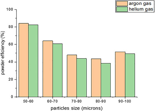
Direct energy deposition (DED) is an efficient manufacturing process for the fabrication of complex parts and repair of worn-out turbine blades. In DED, all the injected powder is not going to melt and solidify due to spattering, reflection, ejection, effect of inert gas, and turbulence around the melt pool. In this study, through numerical simulation, the effect of powder size and inert gas flow under coaxial nozzle was analyzed. The number of particle participation in the melt pool by the effect of inert gas and the size of powder particles were analyzed. The powder particle sizes considered for the study were 50–60, 60–70, 70–80, 80–90, 90–100, and 45–90 µm. Argon and helium gases were used as carrier gas and shielding gas, respectively. According to gas–solid multiphase simulation, the convergence distance of the powder flow and powder participation focal point was analyzed through numerical simulation. The simulated results showed that using argon gas as a carrier gas produced high powder efficiency compared to helium gas. The focal point is forming at 11.86 mm, approximately 12 mm from the nozzle exit, which occurred for 60–70-µm particle size. The powder particle participation efficiency obtained was 64.1% using argon gas as carrier gas.
Introduction
Direct energy deposition (DED) is also called as laser engineered net shaping, direct metal deposition, and 3D laser cladding. This process is generally used to repair or add additional material to the existing component (Graf et al., 2012). The advantages of DED attract various metal part applications in aerospace, automobile, naval, and medical sectors, such as products of jet engines, turbines blades, or implant applications (Schmidt et al., 2017). DED is the most suitable approach to produce a large-scale freeform fabrication due to its high efficiency and the fact that it does not require any strict shielding system. This process has the ability to manufacture a heterogeneous material system with preferred properties and features via successive and concurrent depositions of different materials. In addition, a hybrid process combining DED with different manufacturing processes can be conveniently developed. Hence, research on the DED processes has been progressively increased in recent years. Furthermore, this method is used to repair damaged components, to manufacture new parts, and to apply wear and corrosion resistance coatings (Herderick, 2011). In DED, there are four types of powder feed mechanisms, such as off-axis powder injection, continuous coaxial nozzle, discrete coaxial nozzle, and inside powder-beam injection (Singh et al., 2020). This nozzle gives a higher efficiency only in the case vertical configurations but does not when the part is at an inclined angle due to its negative gravitational effect. This effect can be overcome by another type nozzle called discrete coaxial nozzle. In a powder-beam injection nozzle, the laser beam is divided and projected radially, concentrating at a point, and the powder is fed from the center of the nozzle. Manjaiah et al. (2020) studied the effect of DED process parameters on bead geometry at high-deposition-rate 316L SS powder using a coaxial nozzle. Most DED systems use a coaxial nozzle system in deposition head. It was concluded that the bead geometry was highly affected by scan speed and laser power. Zhong et al. (2015a) experimentally evaluated the effect of process parameters on porosity, bead geometry, deposition rate, and powder efficiency in a DED system using coaxial nozzle. The deposition rate increases, whereas the powder melting efficiency decreases with increased powder mass flow. The conclusions can be utilized to increase the catchment efficiency of the DED system at high deposition rate. Hence, in this work, coaxial nozzle powder feeding mechanism was considered for the numerical simulation. On the other hand, DED still has several problems, e.g., porosity, residual stress, poor accuracy, and reduced powder supply efficiency. In order to address these problems, few researchers have tried to enhance the powder melting efficiency, increased the density of the deposit, and experimentally investigated the effect of process parameters such as powder heating, powder particle size, laser power, and scan speed on melting efficiency (Zhong et al., 2015b).
Pinkerton and Liu (2005) suggested a laser deposition energy distribution model to characterize energy partitioning during the deposition of 316L stainless steel utilizing an 800-W Nd: YAG laser (Pinkerton and Li, 2005). According to his analytical model and experiments results, approximately 54% of the laser power was reflected by the substrate, 30% was absorbed by the substrate, 11% was reflected by the powder, 4% was lost due to dispersed powder, and just 1% was attributed to the deposited powder. Morville et al. (2012) presented a 3D numerical model to evaluate the powder flow of two materials: Ti-6Al-4V alloy and 316L stainless steel. It is concluded that a focal point is found at a distance nearer to the nozzle exit with the stainless steel, and heating of steel particles is lower at the center of the stream due to their inertia (Morville et al., 2012). Tan et al. (2012) developed a photographic system for the powder feeding process of laser solid form using a high-speed camera. The behavior of powder feed, like the particle speed, and the powder concentration were evaluated using the images of powder flow. The distance between nozzle exit plane and powder feed behavior influence the powder feed parameters. By increasing the particle speed, the deposited layer surface was smoothened with a decreased layer height (Tan et al., 2012). The gas-solid two-phase flow theory was used to investigate the effect of deposited layer shape on coaxial powder feeding nozzle in metal forming process as well as the effect of deposited layers on powder concentration distribution and focal point distance from nozzle exit to the convergence point (the center of the convergent zone). They demonstrated that, under unequal wall thickness of component production conditions, the additive height of the layer cladded was not uniform. Due to the uneven thickness of the deposited layer, the surface is not smooth (Zhu et al., 2011). Takemura et al. (2019) investigated the influence of carrier and shielding gas flow rate on the convergence of the powder supply both experimentally and by simulation. The shape of the powder nozzle was redesigned based on the gas–solid multiphase flow simulation to achieve high powder convergence into the melt pool. The powder delivery and stream efficiency were evaluated experimentally, and CFD simulation indicates that shortening the convergence distance of the powder is effective in improving the powder flow convergence. Although given the convergence distance of 8 mm, the powder flow that shows a high convergence became longer with an increase in the carrier gas flow rate of 4 L/min, achieving 66% of powder supply efficiency. The simulation and experimental validation clearly shows that the redesigned nozzle has a higher efficiency than the conventional nozzle in the powder supply (Takemura et al., 2019). Frederick et al. studied the partitioning of laser energy in Ti-6Al-4V, and Inconel 625 alloy was experimented and validated using a unique process calorimeter. The total energy absorbed during the deposition process was determined to be 42% for the Ti-6Al-4V alloy and 37% for the Inconel 625 alloy while processing at a laser power of around 1 kW. While under these conditions, 14% of the total energy is lost by the Ti-6Al-4V unfused powder, whereas the Inconel 625 powder lost only 11% (Lia et al., 2017). Very few literature can be found on considering different gas flow rate, powder flow velocity, and nozzle design in DED.
Focusing on the reduction of the powder supply efficiency and increasing melting efficiency, a complex interaction between the gas flow and the powder interferes with the movement of the powder. The results of this investigation indicated the importance of powder size and supply of shielding and carrier gas, which supported the earlier investigation of powder particle participation in melt pool at a focal point of laser and powder convergence.
Methodology
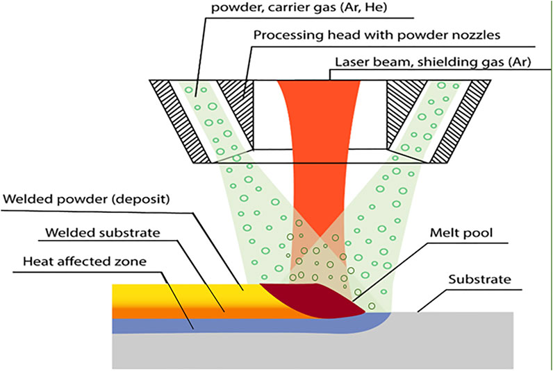
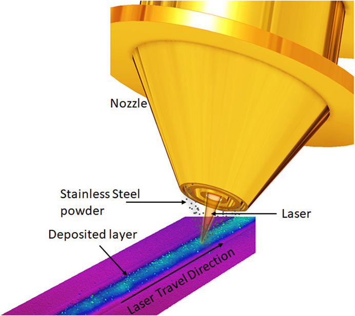
In direct energy deposition, focused thermal energy is used to melt the powder for deposition as per ASTM international standard. In DED, the bead is formed on the substrate supplying metal powder through a coaxial nozzle using inert (Ar, He) carrier gas and with irradiation of a laser beam simultaneously. In the present work, the powder is injected by coaxial nozzle, and laser is irradiated through the central axis as shown in Figure 1. As shown in Figure 2, the metal powder is injected to the melt pool by a carrier gas through the outer flow path, and the shielding gas is supplied through the inner flow path to avoid the oxidation of weld bead deposits. The deposition head moves upward through a layer height, and another layer of material is deposited. This process continues till the part is formed. The process of material melting takes place at the intersection between the powder flow occurring in between the nozzle exit and substrate. This point of convergence is called focal point, and the plane of convergence is called focal plane.
CAD Model of Coaxial Nozzle
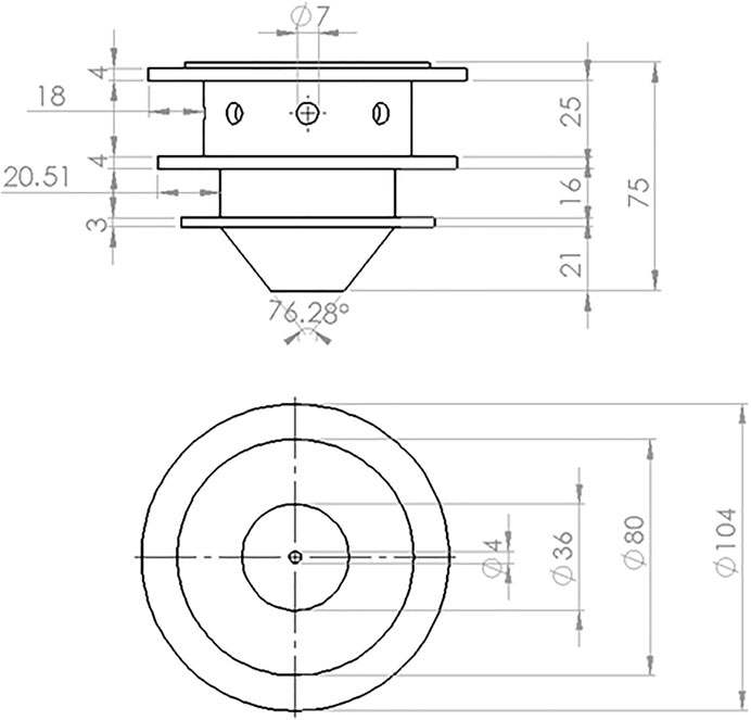
In this continuous coaxial nozzle system, powder is injected through an injection system with laser irradiation at the center of the nozzle, and two flow paths are employed. Figure 3 shows the 3D CAD model of the coaxial nozzle. As shown in Figure 4 the powder and the carrier gas are injected from the inner flow path, and the shielding gas is supplied through the outer flow path. The coaxial nozzle, having the powder feeding from the sideways and laser directed from the center of the nozzle, coincides with the powder at a focal point. From the side, there is a provision made for the entry of powder along with the carrier gas and shielding gas injection made through the pipe from the hopper. The respective dimensions of the coaxial nozzle is taken from BEAM machines (IREPA LASER, (Zhao et al., 2020). The nozzle is constructed in compartments of three. The first compartment is used for the laser beam projection. The second compartment is used for the travel of particles and carrier gas, for which eight inlets are given along the circumference of the nozzle. The last compartment, which is below the particle compartment, is for the shielding gas. The central and outer gas streams ensure the optics protection and oxidation protection, respectively. Normally, inert gas Ar or He is used as carrier and shielding gas, respectively. Hence, in this study, the effect of both gases on particle participation was analyzed numerically.
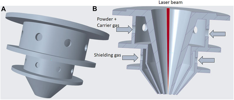
FIGURE 4. Solid model of the coaxial nozzle. (A) Isometric view and (B) cross-sectional view of the coaxial nozzle.
Numerical Simulation
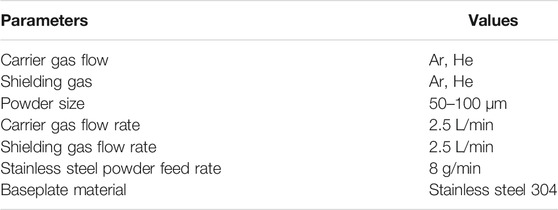
In this study, ANSYS Fluent software was used to simulate the 316L stainless steel powder stream characteristics. The stainless steel powder numerical simulations conditions were reported in Table 1. The gas phase was computed by the standard k-
The governing continuity and momentum equations are expressed as Eqs 1, 2.
where
The sediment particles are tracked in the Lagrangian reference frame to obtain their positions and velocities using the discrete particle model. As the particles are released from the nozzle, they are confined in the flowing inert gas. It plays a dominant role in determining the particle trajectories. Thus, the forces from the air phase are only used to calculate the particle’s movements in the present work as shown in Eq. 3.
where mp is the particle mass,
The other additive equations used to describe the turbulent velocity fluctuation are as follows: the standard turbulence k-
where Gk is the rate of production of turbulent kinetic energy due to average velocity gradient, Gb is the generation of turbulence owing to buoyancy, Prt is the turbulence Pradntl number, and
Following are the assumptions made in the design and simulation process of the work (Takemura et al., 2019):
• The 3D model of the nozzle has been designed in solid works, but actual simulation was carried out considering a 2D plane of the designed CAD model.
• The dimensions considered are approximately close to the actual working model of the coaxial nozzle with particular assumptions.
• All particles in the simulation process are considered spherical in shape.
• The collision among particles in the passage of the nozzle is neglected.
• The gravitational effect on the particles is considered.
• Default values of the properties of argon gas and helium gas are considered.
• Laser simulation is not considered in this work; the point where the all the particles concentrate is instead considered as the laser interaction point.
• The space between the nozzle exit and the substrate is considered imaginary, and an imaginary plane is considered at the focal point to collect the trapped particles.
• The simulation work of the process is done in Ansys 2020 R2, in which the workbench of fluent is used to define the flow of particles in the nozzle simulation. The designed CAD model is imported to the Ansys fluent geometry workbench, and a 2D model is generated.
The CAD model is imported to Ansys, the plane of the substrate surface is subdivided into three planes in order to have provision to collect the particles which are being melted and the particles which are escaping from the melting zone. An imaginary plane is created between the nozzle exit and the substrate surface for the particles to concentrate at a point.
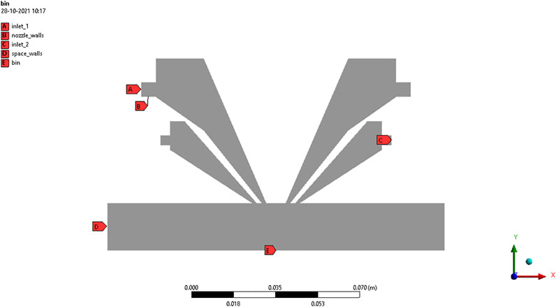
The 2D model is imported to the meshing tool where meshing and required boundary conditions are applied. E, designated as inlet 1 in Figure 5, is the inlet for powder particles and carrier gas. A, being inlet 2, is the inlet for shielding gas. B, representing the bin, is the boundary to collect melted particles. C, as the imaginary space bottom plane, is the boundary to collect unmelted particles. D is the nozzle wall boundary condition, and F specifies the space wall boundary conditions.
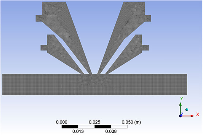
Meshing of element size 0.5 mm is applied to the geometry with quadrilateral element order as shown in Figure 6. A fine element size is considered in smoothing the mesh. All the remaining parameters of the mesh tool are taken as default parameters.
In simulation of the work, three models were considered. They are multiphase Eulerian model, k-ε turbulent model, and dense discrete phase model. In multiphase Eulerian model, two Eulerian phases are taken into consideration and one discrete phase is considered. In injection type, the surface injection with release of particles is selected from inlet 1 being the inlet for particles and carrier gas. The material of the particles is stainless steel 316L particles with Rosin–Rammler diameter distribution. The inlet velocity of the particles is taken as 0.25 m/s, and the total flow rate is 8 g/min. The particles are relatively spherical through the simulation process for every particle size.
To analyze the influence of Ar and He gas flow and the powder particle size on powder participation in the melt pool, a gas solid multiphase flow simulation model is conducted by using Ansys Fluent. The powder distribution analysis was made by assuming the baseplate under the powder nozzle. From the conclusions of Takemura et al. (2019), 2 to 3 L/min of carrier and shielding gas was found to have maximum powder efficiency for both numerical and experimental analyses. Hence, in this study, 2.5 L/min gas flow rate was considered for the numerical simulation.
Grid Independency Test
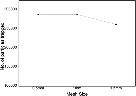
To validate the numerically simulated results, grid indecency test was conducted by varying the number of mesh and number of cells of the nozzle design. The number of powder particles trapped in the bin was considered for all the mesh size with Ar as the carrier and shielding gas. It seems that, by increasing or decreasing the number of cells, the powder particles trapped in the bin are more or less the same, as depicted in Figure 7. Hence, 0.5-mm mesh size is considered for all the powder particle size distributions.
Experimental Validation of Results
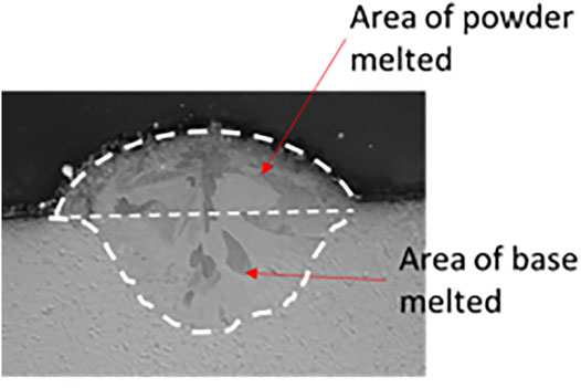
To verify the trajectory of powder flow and powder particle participation in the melt pool, the numerical simulation results were correlated experimentally using DED (IREPA) process. The experiments were made at a focal distance (Z) of 10 mm using 45–90 µm SS 316L powder, and the powder particles were collected and measured for the number of particles that participated and escaped from the zone. It was observed that the particle participation is almost 45% in the experimental condition as per the weight fraction measurement and is around 41.66% in the numerical simulation as can be seen in Figure 8. It has also been verified by depositing a single bead on the steel substrate. It was confirmed that the melting efficiency was about 51% as per the cross-section area of the bead (Figure 9).
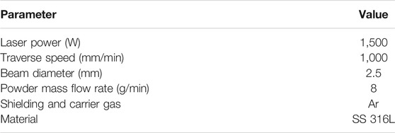
To keep the experimental parameters similar as in the numerical computation, a single bead deposition was made as shown in Figure 7. The standoff distance was set to 10 mm from the nozzle outlet to the coaxial convergence of laser and powder in the flight mode. The process parameters of the laser cladding experiment are shown in Table 2. The length of the single-bead cladding layer was 80 mm. A cross-section of the single-bead cladding layer was obtained as shown in Figure 8, where the area of melted powder is 0.784 mm2. To measure the area, Olympus optical profilometer was used.
Results and Discussions
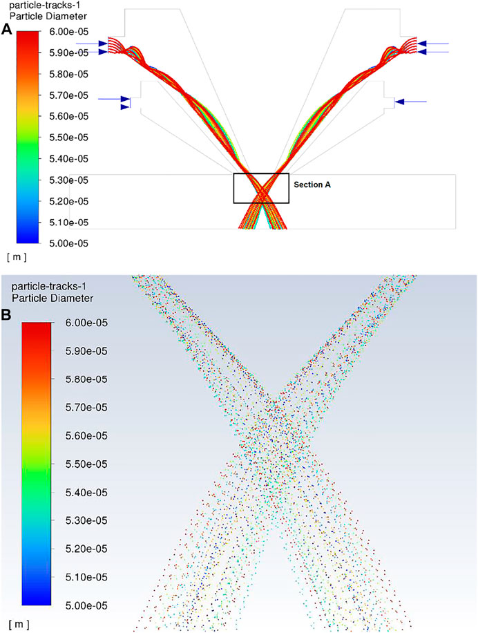
The results show that the flow under the powder nozzle becomes turbulent and indicate the validity of applying the turbulent flow model in this simulation (Zhu et al., 2011). To investigate the convergence of the powder flow, velocity of powder, convergence distance from nozzle exit, and percentage of converged powder in the bin for various powder sizes and inert gas flow, the 2D CAD model is considered. The simulation result shows powder particle tracks flowing from the inlet of the nozzle to the exit and concentrating at the focal point below the nozzle exit. The particles that diverged from the point of concentration and deposited on the substrate surface were evaluated. Figure 10 illustrates the powder particle simulation for 50–60-µm size with argon as the carrier gas.
The contour of the velocity profile of argon and helium gas is shown in Figure 11. The velocity increases when the gas touched the focal point, and beyond the focal point, the gas flowed outwards into the space. Velocity increased at the nozzle exit, and beyond the nozzle exit for He gas, the gas flowed outwards into the space, resulting in the formation of swirls. This may have caused a Marangoni effect in the molten pool. The surface tension gradient is causing the mass transfer to take place along the interface of two fluids, which can be the reason for a possible Marangoni effect.
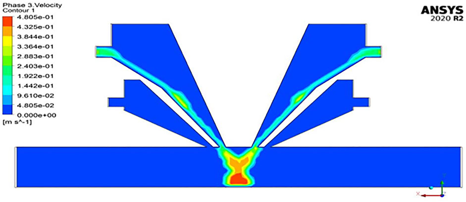
The contour of the particle velocity profile of phase is shown in Figure 12, which is the discrete phase of the particle. The particles, after intersecting at the focal point, have the highest velocity due to gravitational effect and which may be due to the particle interaction. The maximum velocity reached by the particles is 0.48 m/s. The results show that the powder flow convergence increases with Ar as carrier gas, and the powder flow rate matches with the gas. This is due to the particle velocity becoming greater with intensification in the carrier gas flow rate (Takemura et al., 2019).
Effect of Powder Particle Size on Convergence
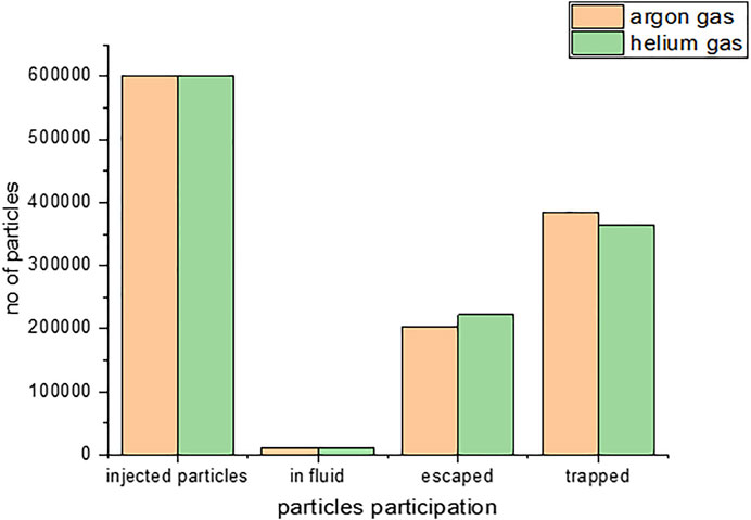
The stainless steel powder particle flowability, convergence, and participation of powder particle in the melt pool trap were identified using flow 3D for several sizes. As shown in Figure 13 the particles converged at the focal point, which is formed at a distance of 12.59 mm from the nozzle exit and the width of powder distribution being 2.47 mm at the focal point. Figure 12(b) illustrates the number of particle participation in the melt pool trap, those that escaped, and those in the nozzle for both Ar and He as carrier gases for stainless steel powder. The particle simulation report was obtained from flow 3D for Ar and He as carrier gas.

FIGURE 13. Simulated results of particle convergence particle participation for 50–60 µm size. (A) Particles track at exit of the nozzle (B) Particles participation in melt pool.
For argon as carrier gas, the number of particles injected from the nozzle inlet was 600,000. The particles collected at the focal point and participating in melting are called trapped particles, the number of which was 505,245, and the number of particles that escaped was 80,573. At a particular time of trapping, there are 14,182 particles in the fluid.
For helium as carrier gas, the same number of particles was carried in He gas for the injection. The particles collected at the focal point, the number of which was 494,454, and the number of particles that escaped was 91,364. At a particular time of trapping, there are 14,182 particles in the fluid.
Given 60–70-µm powder particle size, Figure 14 shows the convergence for the 60–70 µm-range of particle size at a focal point which is formed at a distance of 11.86 mm from the nozzle exit. The width of powder distribution at the focal point was 4.48 mm. Figure 14 illustrates the number of particles participating in the melt pool trap, those that escaped, and those in the nozzle for both Ar and He as carrier gases for stainless steel powder. A particle simulation report was obtained from flow 3D of Ar and He gases. Results are shown considering a range of particle size of 60–70 µm, with argon gas as carrier and helium as shielding gas.
Similarly, simulations of powder particle sizes of 60–70, 78–80, 80–90, 90–100, and 45–90 µm were also done to verify the focal point of convergence and the width of powder convergence for both Ar and He as the carrier gases. Table 3 represents the particle convergence focal point distance, width, as well as powder particle participation in the melt pool.
Comparative Results of Powder Particle
Figure 15 illustrates the comparison between effects of particle size, focal distance, and the number of particles trapped in the melt pool with an assumption of bin below the focal point. It indicates that, for Ar gas, the particle trapping rate is high compared to He as carrier gas for any size of the particles.
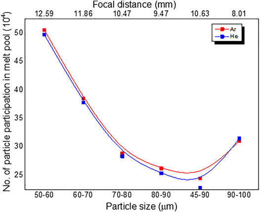
FIGURE 15. Stainless steel powder particle participation in melt pool vs. various powder size of argon and helium as carrier gas.
Even though a greater number of particles was trapped at 50–60-µm particle size, from Table 3, it can be observed that the distance between the focal point and the nozzle exit was 12.59 mm, which was not optimum distance according to the experimental study conducted by various authors (Zekovic et al., 2007; Alvarez et al., 2018). The optimum distance between the focal point and the nozzle exit is around 12 mm, which is obtained for a particle size of 60–70 µm. The powder trapping efficiency was calculated as follows:
where M2 = number of particles trapped and M1 = total number of particles injected.
Figure 16 shows the powder trapping efficiency of various powder size distributions for both Ar and He as carrier gas. It was observed that Ar as carrier gas has higher powder participation efficiency for all the powder size distributions, and 50–60 µm has the highest powder participation efficiency compared to the remaining size, but the focal point distance is around 12.6 mm which is close to that in practical experimental conditions that have the highest melting efficiency and uniform weld bead formation in laser direct energy deposition of 316 stainless steel powder (Wu et al., 2018). To meet the high tolerance standards required in laser direct energy deposition process, argon and helium are commonly used to provide inert atmospheres and protect the beads from the oxidation. Even nitrogen gas is used for carbon steel fabrication and other materials. The choice of optimal process gas depends on the material quality requirements. Even during the atomization process, argon is highly used for powder production, and also it will influence the microstructure. Hence, attempt is made here to verify the influence of gas on the powder particle as well as on the shielding effect. The shielding gas compacts the powder flow, reducing the effect of both the gravity force and carrier gas inertia that are mainly responsible for powder spreading in powder flow.
Powder flowability mainly depends on the distribution, size, and shape of powder particles. Sphericity is a significant factor for good flowability of metal powders. Particle size distribution is another important parameter—for example, a wide particle size distribution can affect the packing behaviors and, consequently, bead shrinkage and densification of molding parts.
The flowability of metal powders is not an inherent property—it depends not only on the physical properties (shape, particle size, humidity, etc.) but also on the stress state, the equipment used, and the handling method. The powder flow properties in different additive technologies are a complex area for study. Powder companies would like to avoid flow problems such as segregation, vaulting, and agglomeration and want to predict how a particular metal powder will flow and form/not form a homogeneous layer or compare the flow characteristics of metal powders with each other. Due to the expensive cost of metal powders, only a limited amount is provided for testing, so it is favorable to test different powder size distribution effects in DED process.
Conclusion
To enhance the powder melting efficiency in DED, the influence of powder nozzle geometry, powder carrier gas, and powder size distribution on the convergence of powder supply was studied using numerical simulation. From the results obtained from the numerical simulation, the following conclusions are drawn:
• High powder efficiency is obtained for argon as carrier gas compared to using helium gas for any distribution of particle size.
• Helium, being lighter than argon, needs to have 10 times more gas pressure and velocity to have the same particle participation in the melt pool. Hence, more particles are deviating from the focal point.
• The focal plane was formed at 11.86 ≈ 12 mm, which is the optimum distance between the nozzle exits and build plate to have a higher melt pool efficiency.
• Powder particle size of 60–70 µm has a greater powder participation efficiency, which is around 64.1% for argon gas as carrier gas and helium gas as shielding gas.
Data Availability Statement
The original contributions presented in the study are included in the article/supplementary material. Further inquiries can be directed to the corresponding author.
Author Contributions
The problem statement was defined by MM. Computational fluid dynamics simulation was carried out by HK. The paper was written by HK and MM.
Conflict of Interest
The authors declare that the research was conducted in the absence of any commercial or financial relationships that could be construed as a potential conflict of interest.
Publisher’s Note
All claims expressed in this article are solely those of the authors and do not necessarily represent those of their affiliated organizations or those of the publisher, the editors, and the reviewers. Any product that may be evaluated in this article or claim that may be made by its manufacturer is not guaranteed or endorsed by the publisher.
References
Alvarez, P., Montealegre, M., Pulido-Jiménez, J., and Arrizubieta, J. (2018). Analysis of the Process Parameter Influence in Laser Cladding of 316L Stainless Steel. JMMP 2, 55. doi:10.3390/jmmp2030055
Arrizubieta, J. I., Tabernero, I., Ruiz, J. E., Lamikiz, A., Martinez, S., and Ukar, E. (2014). Continuous Coaxial Nozzle Design for LMD Based on Numerical Simulation. Phys. Proced. 56, 429–438. doi:10.1016/j.phpro.2014.08.146
Graf, B., Gumenyuk, A., and Rethmeier, M. (2012). Laser Metal Deposition as Repair Technology for Stainless Steel and Titanium Alloys. Phys. Proced. 39, 376–381. doi:10.1016/j.phpro.2012.10.051
Herderick, E. (2011). “Additive Manufacturing of Metals: A Review,” in Materials Science & Technology Conference & Exhibition 2011-MS T’11, Columbus, OH, 1413–1425. Available at: http://www.scopus.com/inward/record.url?eid=2-s2.0-84856301323&partnerID=40&md5=e02018d10b2ca37a7e2ae1773e4fcaec.
Li, L., Huang, Y., Zou, C., and Tao, W. (2021). Numerical Study on Powder Stream Characteristics of Coaxial Laser Metal Deposition Nozzle. Crystals 11, 282. doi:10.3390/cryst11030282
Lia, F., Park, J., Tressler, J., and Martukanitz, R. (2017). Partitioning of Laser Energy during Directed Energy Deposition. Addit. Manuf. 18, 31–39. doi:10.1016/j.addma.2017.08.012
Manjaiah, M., Hascoët, J. Y., and Rauch, M. (2020). Effect of Process Parameters on Track Geometry, Microstructural Evolution on 316L Stainless Steel Multi-Layer Clads. Mater. Sci. Eng. B 259, 114583. doi:10.1016/j.mseb.2020.114583
Morville, S., Carin, M., Carron, D., Le Masson, P., Gharbi, M., Peyre, P., et al. (2012). “Numerical Modeling of Powder Flow during Coaxial Laser Direct Metal Deposition – Comparison between Ti-6Al-4V Alloy and Stainless Steel,” in 2012 COMSOL Conference (Milan). Available at: http://www.comsol.com/paper/numerical-modeling-of-powder-flow-during-coaxial-laser-direct-metal-deposition-c-13191.
Pinkerton, A. J., and Li, L. (2005). Direct Additive Laser Manufacturing Using Gas- and Water-Atomised H13 Tool Steel Powders. Int. J. Adv. Manuf. Technol. 25, 471–479. doi:10.1007/s00170-003-1844-2
Schmidt, M., Merklein, M., Bourell, D., Dimitrov, D., Hausotte, T., Wegener, K., et al. (2017). Laser Based Additive Manufacturing in Industry and Academia. CIRP Ann. 66, 561–583. doi:10.1016/j.cirp.2017.05.011
Singh, A., Kapil, S., and Das, M. (2020). A Comprehensive Review of the Methods and Mechanisms for Powder Feedstock Handling in Directed Energy Deposition. Addit. Manuf. 35, 101388. doi:10.1016/j.addma.2020.101388
Takemura, S., Koike, R., Kakinuma, Y., Sato, Y., and Oda, Y. (2019). Design of Powder Nozzle for High Resource Efficiency in Directed Energy Deposition Based on Computational Fluid Dynamics Simulation. Int. J. Adv. Manuf. Technol. 105, 4107–4121. doi:10.1007/s00170-019-03552-1
Tan, H., Zhang, F., Wen, R., Chen, J., and Huang, W. (2012). Experiment Study of Powder Flow Feed Behavior of Laser Solid Forming. Opt. Lasers Eng. 50, 391–398. doi:10.1016/j.optlaseng.2011.10.017
Wu, J., Zhao, P., Wei, H., Lin, Q., and Zhang, Y. (2018). Development of Powder Distribution Model of Discontinuous Coaxial Powder Stream in Laser Direct Metal Deposition. Powder Techn. 340, 449–458. doi:10.1016/j.powtec.2018.09.032
Zhao, L., Yue, H., Guo, C., Li, Q., and Hao, G. (2020). Analytical Modelling and Experimental Study of the Cladding Characteristics of a Laser Powder-Fed Additive Manufacturing Process. Int. J. Adv. Manuf. Techn. 109 (9), 2891–2900. doi:10.3390/cryst11111306
Zekovic, S., Dwivedi, R., and Kovacevic, R. (2007). Numerical Simulation and Experimental Investigation of Gas-Powder Flow from Radially Symmetrical Nozzles in Laser-Based Direct Metal Deposition. Int. J. Machine Tools Manufacture 47, 112–123. doi:10.1016/j.ijmachtools.2006.02.004
Zhong, C., Biermann, T., Gasser, A., and Poprawe, R. (2015). Experimental Study of Effects of Main Process Parameters on Porosity, Track Geometry, Deposition Rate, and Powder Efficiency for High Deposition Rate Laser Metal Deposition. J. Laser Appl. 27, 042003. doi:10.2351/1.4923335
Zhong, C., Gasser, A., Schopphoven, T., and Poprawe, R. (2015). Experimental Study of Porosity Reduction in High Deposition-Rate Laser Material Deposition. Opt. Laser Techn. 75, 87–92. doi:10.1016/j.optlastec.2015.06.016
Keywords: additive manufacturing, computational fluid dynamics, powder size, direct energy deposition, stainless steel
Citation: Kumar H and M M (2022) Numerical Simulation of Stainless Steel Powder Feeding in a Coaxial Nozzle for High Powder Efficiency in Laser Direct Energy Deposition. Front. Mech. Eng 8:763112. doi: 10.3389/fmech.2022.763112
Received: 23 August 2021; Accepted: 12 January 2022;
Published: 17 February 2022.
Edited by:
Vamsi Krishna Balla, Central Glass and Ceramic Research Institute (CSIR), IndiaReviewed by:
Srikanth Bontha, National Institute of Technology, IndiaAmit Bandyopadhyay, Washington State University, United States
Copyright © 2022 Kumar and M. This is an open-access article distributed under the terms of the Creative Commons Attribution License (CC BY). The use, distribution or reproduction in other forums is permitted, provided the original author(s) and the copyright owner(s) are credited and that the original publication in this journal is cited, in accordance with accepted academic practice. No use, distribution or reproduction is permitted which does not comply with these terms.
*Correspondence: Manjaiah M, bWFuamFpYWgubUBuaXR3LmFjLmlu
 Hemanth Kumar
 Manjaiah M