 A. Parrinello
 W. Belgacem1
 S. Ghinet
- 1Department of mechanical Engineering, Université de Sherbrooke, Sherbrooke, QC, Canada
- 2National Research Council Canada, Ottawa, ON, Canada
The present work describes the use of a transfer matrix method to define the acoustic behavior of multilayered and periodic baffled curved shells consisting of a generic arrangement of homogeneous and heterogeneous periodic layers of various nature (fluid, solid, and poroelastic). The dynamic stiffness matrix of a unit cell is manipulated in order to derive the through-radius transfer matrix of a cylindrical periodic layer. Thus, the acoustic radiation or transmission of multilayered shells can be assessed. The blocked pressure field due to an incident plane wave is defined by taking into account the infinite rigid baffle by means of a two-dimensional boundary element model. Analytical expressions for the cylindrical acoustic impedances are utilized to define the coupling with the bounding fluid media. Furthermore, a one-dimensional windowing technique is adopted to account for the finite length of the shells. The proposed approach is validated by systematic comparison with a full finite-boundary element method.
1 Introduction
The numerical evaluation of the sound Transmission Loss (TL) through baffled curved shells with attached sound packages is of importance in many industrial applications such as fairings, aircraft fuselages and submarines. The baffle mimics the installation of such panels in a transmission loss suite. In theory, this problem can be solved accurately using a combined Finite Element (FE)—Boundary Element (BE) method. The calculation is usually done in two steps Atalla and Sgard (2015). In the first a scattering problem is solved to calculate the blocked pressure on the surface of the shell. Next, the coupled FE-BE vibro-acoustic problem is solved to calculate the power radiated by the elastic shell into the receiver medium. An alternative method uses Adaptive Perfectly Matching Layers (APML) instead of a BE description of the radiation problem. These methods, while nowadays classical, are however computationally extensive and are thus limited to low frequencies. There is in consequence an interest in using semi-analytical methods for these type of problems. Over the years several formulations have been developed for the TL of elastic multilayered shells (i.e., homogenous, sandwich-composites) Ghinet et al. (2005), Ghinet et al. (2006), sandwich cylinders including porous layers Magniez et al. (2014),Magniez et al. (2016). An overview can be found in the introduction of Parrinello et al. (2020b). To correct for the finite size of the structure a windowing approach, such as the ones described in Villot et al. (2001), Rhazi and Atalla (2010), can be used. However, these semi-analytical approaches are limited to homogenous layers. In consequence, computationally efficient tools are still needed for more complex structures and excitations. One such approach was presented by Kessour et al. (2020). It is a substructuring method that employs a Patch Transfer Functions (PTF) approach to couple through a Green’s function formalism standard FE method of the structure and the acoustic cavity with a Transfer Matrix Method (TMM) for the sound package. However, the approach remains limited since analytical expressions for the transfer matrices are only available for homogeneous planar media of infinite extent Allard and Atalla (2009). To account for the size effect a source image method is used. Another approach uses Wave FE (WFE) wherein the complexity (geometry and material properties) is accounted for via a FE model of a periodic representative Unit Cell (UC) Manconi E. and Mace B. (2010), Kingan et al. (2016), Errico et al. (2019a). Errico et al. (2019b) uses this approach to predict the TL of curved panels with added sound packages. Again, the sound package is modeled using the classical TMM and is thus assumed flat and homogeneous. This paper presents an alternative approach alleviating this limitation. It is based on a periodic FE based TMM wherein the complexity of the structure and the sound package are explicitly included in the FE model of the representative UC. Wave propagation in periodic media has been first discussed by Brillouin (1946) in the field of electrical engineering. Afterwards, wave propagation in non-uniform periodic structures has been treated by Mead (1973) and Abrahamson (1973) with the Rayleigh-Ritz technique and by Orris and Petyt (1974, 1975) with FE techniques. While the WFE method is mainly used for the analysis of the elastic waves propagation in periodic media Mace and Manconi (2008); Manconi E. and Mace B. R. (2010), applications for the sound transmission through sandwich structures have been recently proposed Christen et al. (2016); Yang et al. (2017); Errico et al. (2018, 2019a). By exploiting the WFE approach, the transfer matrix of a periodic planar layer is obtained first in case of small UCs in Parrinello and Ghiringhelli (2016) and afterwards in case of large UCs in Parrinello et al. (2020a) by accounting for Bloch modes. A TMM for the sound transmission through infinite heterogeneous cylinders is presented in Parrinello et al. (2020b). In this paper, an extension of the latter method for finite long and baffled heterogeneous curved shells is presented. A two-dimensional (2D) BE model is employed to evaluate the blocked pressure on the outer surface of the baffled shell while the response of the multilayered shell to the blocked pressure (excitation) is modeled by means of a generalized TMM which make it possible to model heterogeneous periodic layers. The present work differs from Parrinello et al. (2020b) in 1) the calculation of the blocked pressure due to a plane wave excitation impinging on the cylindrical shell embedded in an infinite planar rigid baffle and in 2) applying a one-dimensional (1D) windowing technique to account for the effect of the finite length of the shell on the transmitted power. Details about the definition of the transfer matrix of a layer and the assembly can be found in Parrinello and Ghiringhelli (2016); Parrinello et al. (2020a,b).
First, the modeling of the plane wave excitation by means of a 2D BE approach is presented, the coupling with external and internal fluid media are recalled and the windowing correction applied along the longitudinal axis is described. Then, the proposed approach is validated first for shells consisting of homogeneous layers by comparison with full three-dimensional (3D) FE-BE models of the baffled shells. Finally, an application to the prediction of the TL of a cylindrical shell covered by a layer of resonators is discussed to illustrate the practical use of the approach.
2 Theory
Figure 1 depicts the midplane of a generic multilayered baffled cylindrical shell. The longitudinal axis of the shell is parallel to the x-axis and the infinite baffle lies on the x − y plane. The shell has the length L, inner radius ri and outer radius ro. Subscripts i and o indicate values at the inner and outer surfaces. The baffle and the two bulkheads at the ends of the shell are assumed rigid. Throughout the analysis time-harmonic motion of the form exp(jωt) is assumed. The boundary composed of the shell, the infinite baffle and the bulkheads separates two semi-infinite fluid media. The defined sound speeds c− and c+ as well as the densities ρ− and ρ+ are associated to the fluid in the half spaces z < 0 and z > 0 respectively. The shell is excited by an oblique plane wave traveling in the half space z < 0 with incident angle, θ, with respect to the z-axis and heading angle, Ψ, with respect to the x-axis, as depicted in Figure 1. The auxiliary angle β is defined in the y − z plane as tan β = tan θ sin Ψ Blaise and Lesueur (1992).
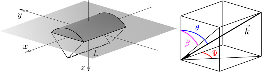
FIGURE 1. System’s geometry in the x − y − z space.
The sound transmission through the structure is modeled assuming a shell of infinite extent along the x-axis. Such a selection makes it possible to 1) model the shell dynamics by exploiting a double periodicity which, in turn, makes it possible to exploit the layer-wise approach of the TMM, 2) solve the acoustic scattering problem in the y − z plane and 3) exploit analytical expressions for the acoustic impedances at the inner and outer surface of the shell. First, the acoustic field produced by the scattering of the incident field on the baffled shell must be evaluated. Because of the above mentioned hypothesis, a 2D scattering problem must be solved in the y − z plane. Therefore, the blocked pressure on the outer surface of the shell must be projected on the circumferential modes in order to apply the analytical expressions of cylindrical acoustic impedances. For each couple of longitudinal wavenumber and circumferential mode, the transmission through the multilayered shell can be evaluated by means of the TMM described in Parrinello et al. (2020b) using the blocked pressure obtained from the 2D scattering problem. Finally, a windowing corrections along the x-axis is applied to the total transmission coefficient in order to take into account the finite length of the shell.
2.1 Blocked pressure in the y − z plane
The incident pressure field due to a plane wave can be expressed in cylindrical harmonics using the Jacobi-Anger expansion as Abramowitz and Stegun (1965).
where p0 is the amplitude of the incident wave, n is the circumferential mode number, ɛn is the Neumann factor (ɛn = 1 if n = 0, ɛn = 2 if n > 0) and the wavenumber components, kx and k−, are expressed as
We are interested in the blocked acoustic field, p, resulting from the scattering of the incident pressure field impinging on the boundary composed of the infinite long shell and the infinite baffle. The baffle can be replaced with the image of the shell with respect to the x − y plane, thus obtaining a scattering problem defined on a finite rigid surface Atalla and Sgard (2015):
where x and y belong to the boundary ∂Ω, i.e., the outer surface of the shell,
In order to solve the integral equation, Eq. 3, the boundary ∂Ω is discretized into Ne equally-long straight elements:
where vector p contains the pressure values at the elements, vector pinc expresses the values of the incident pressure at the elements’ midpoints, l is the length of the elements, I is the identity matrix of size Ne, elements of matrix A can be expressed as
where
and
elements of matrix
where
and
Once the linear system, Eq. 5, is solved for p, the blocked pressure coefficients, pn, can be evaluated as
where n is the circumferential mode number and angle δ is defined in Figure 2.
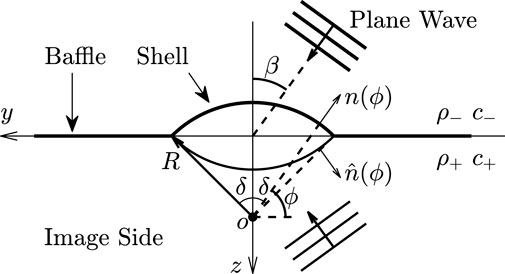
FIGURE 2. System’s geometry on the y − z plane.
2.2 Acoustic impedances
Assuming a non-resonant interior, the acoustic normal impedance at the outer (inner) surface is Parrinello et al. (2020b).
where ρ−(+) and c−(+) are the density and the speed of sound of the z−(+) fluid,
2.3 Windowing along the x-axis
A wave of wavenumber kp is assumed to propagate on an infinite 1D structure. The velocity field in the spatial domain can be written as
The radiated power calculated from the wavenumber spectrum of the velocity field is Fahy and Gordonio (2007).
where ρ and c are the density and the speed of sound of the fluid in which the structure radiates the acoustic power and k0 = ω/c. Finally, the radiation efficiency of the finite length 1D structure can be calculated as Fahy and Gordonio (2007).
2.4 Sound transmission loss
The incident acoustic power per unit length on the outer surface of the shell (r = ro) is given by
On the other hand, the transmitted acoustic power per unit length of the inner surface (r = ri) can be expressed as
with
Thus, the transmission coefficient related to each circumferential harmonic, n, can be expressed as
and the total transmission loss is defined as
where the radiation efficiency, σ(kx), takes into account the finite length of the shell along the x-axis using Eq. 16.
3 Applications
In this section several examples are used to illustrate the validity and applications of the proposed approach. Shells with both homogeneous and heterogeneous layers are considered. Details about the handling of homogeneous layers and the convergence criterion for harmonics can be found in Parrinello et al. (2020b). The fluids properties are c− = c+ = 340 ms−1 and ρ− = ρ+ = 1.284 kgm−3 for all the cases.
To validate the 2D BE implementation and the 1D windowing technique adopted, two configurations involving homogeneous layers are considered. The first case concerns the TL at oblique incidence through a 0.5 m long semi-cylindrical shell with mean radius R = 1 m consisting of a single 2 mm thick steel layer (Nz = 20). The steel has properties: E = 210 GPa, ν = 0.3, η = 0.1%, ρ = 7800 kgm−3. Figure 3 presents the comparison of the TL predicted by the proposed approach (TMM) with the result produced by a 3D FE-BE model (SimCenter 3D-acoustics is used in this study; the approach uses the same steps; first a scattering problem is solved to compute the blocked pressure; then the radiation problem is solved to compute the transmitted power). In case of TMM results, dips are related to scattering effects due to the baffle and to ring frequencies (circumferential modes). In case of full FE-BE results, additional dips are related to scattering effects due to the bulkheads (which are not modeled with the employed 2D BE model) and to longitudinal modes (which are not modeled with the TM approach). As expected, despite a severe modal behavior of the shell (the selected high damping was made on purpose to facilitate the comparison), the TMM provides a good approximation of the upper envelope of the TL over the whole frequency range explored, especially in the mass-law region (above 1 kHz). Moreover, the adopted windowing correction considerably improves the accuracy of TL calculation at low frequencies.
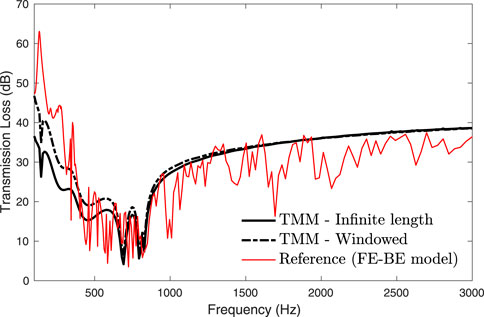
FIGURE 3. TL at oblique incidence (θ = 45°, Ψ = 0°) through a 2 mm thick steel shell (R = 1 m, L = 0.5 m, δ = 90°).
The second case concerns a baffled semi-cylindrical sandwich shell of length L = 1 m, internal radius ri = 1 m and external radius ro = 1.022 m. The shell consists of an external 2 mm thick steel layer (E = 210 GPa, ν = 0.3, η = 0.1%, ρ = 7800 kgm−3), a 19 mm thick melamine core (Φ = 0.99, σ = 10900 Nsm−4, α∞ = 1.02, Λ = 100 μm, Λ′ = 130 μm, E = 80 kPa, ν = 0.4, μ = 17%, ρ = 8.8 kgm−3) and an internal 1 mm thick mass layer (E = 1 MPa, ν = 0.3, μ = 50%, ρ = 1500 kgm−3). The melamine is modeled as an equivalent fluid according to a limp model Allard and Atalla (2009). Figures 4–6 compare the TL at oblique incidences (θ = 45°, Ψ = 0|45|90°) predicted by the proposed approach with the result produced by a 3D FE-BE model. A good agreement is observed between the methods over the whole explored frequency range. Again, the adopted 1D windowing technique improves the agreement with the reference solution in the low frequency range. In case of Ψ = 90° the longitudinal wavenumber, kx, is null and the used windowing cannot be applied.
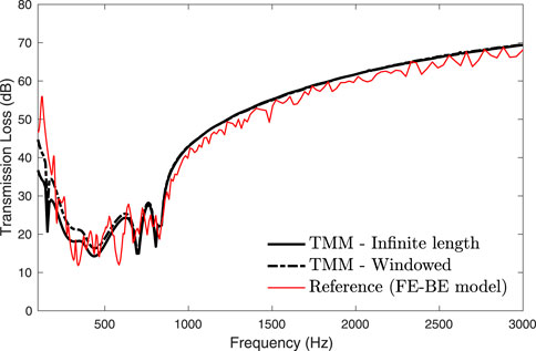
FIGURE 4. TL at oblique incidence (θ = 45°, Ψ = 0°) through a sandwich shell (ri = 1 m, L = 1 m, δ = 90°).
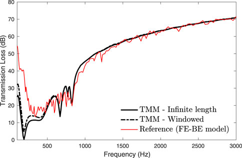
FIGURE 5. TL at oblique incidence (θ = 45°, Ψ = 45°) through a sandwich shell (ri = 1 m, L = 1 m, δ = 90°).
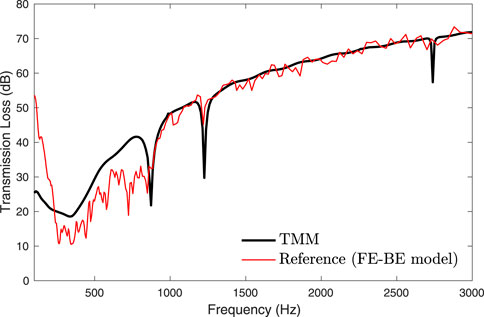
FIGURE 6. TL at oblique incidence (θ = 45°, Ψ = 90°) through a sandwich shell (ri = 1 m, L = 1 m, δ = 90°).
The last case concerns the diffuse acoustic field (DAF) TL through an infinite long semi-cylinder (R = 1.2 m) consisting of a 3 mm thick steel layer (Nz = 20, E = 210 GPa, ν = 0.3, η = 0.1%, ρ = 7800 kgm−3) and an external layer made up from periodically positioned Helmholtz resonators. The geometry of the resonator is selected to tune its resonant frequency to the ring frequency of the bare shell (∼700 Hz) and is described in Parrinello et al. (2020b). A 0.1% of damping is applied to the air inside the resonators. Figure 7 shows the TL through the semi-cylinder under a DAF excitation along with the case with no resonators. As expected (the problem is well studied for planar structures) the resonators layer suppresses the dip at the ring frequency (∼700 Hz) and alleviates the dip corresponding to the critical frequency of the bare shell (∼4 kHz) thus providing an overall improvement of the transmission performance of the semi-cylinder over the entire frequency range explored.
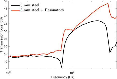
FIGURE 7. TL for DAF excitation through a 3 mm thick steel shell (R = 1.2 m, δ = 90°) covered by a layer of Helmholtz resonators.
4 Concluding remarks
A model for the sound transmission through baffled curved multilayered shells is described. The proposed methodology simplifies the modeling of anisotropic, poroelastic and heterogeneous multilayered shells by combining the versatility of the TM method and the FE method. The accuracy of the method has been verified by the agreement with results obtained using FE-BE models in case of shells consisting of homogeneous layers. The adopted 1D windowing technique makes it possible to properly account for the finite length of the shells. A lower computational cost compared to full 3D models and other periodic approaches is guaranteed since each layer is modeled in isolation. Ultimately, the proposed approach could represent an effective acoustic tool for baffled cylindrical shells, due to its versatility and efficiency.
Data availability statement
The original contributions presented in the study are included in the article/supplementary material, further inquiries can be directed to the corresponding author.
Author contributions
AP and NA contributed to conception and design of the study. AP performed the TMM analysis. WB and SG performed the FE-BE analysis. AP wrote the first draft of the manuscript. All authors contributed to manuscript revision, read, and approved the submitted version.
Acknowledgments
The authors would like to thank the National Sciences and Engineering Research Council of Canada (NSERC) and the Consortium for Research and Innovation in Aerospace in Quebec (CRIAQ) for providing financial support.
Conflict of interest
The authors declare that the research was conducted in the absence of any commercial or financial relationships that could be construed as a potential conflict of interest.
Publisher’s note
All claims expressed in this article are solely those of the authors and do not necessarily represent those of their affiliated organizations, or those of the publisher, the editors and the reviewers. Any product that may be evaluated in this article, or claim that may be made by its manufacturer, is not guaranteed or endorsed by the publisher.
References
Abrahamson, A. L. (1973). Flexural wave mechanics - an analytical approach to the vibration of periodic structures forced by convected pressure fields. J. Sound. Vib. 28, 247–258. doi:10.1016/S0022-460X(73)80105-1
Abramowitz, M., and Stegun, I. A. (1965). Handbook of mathematical functions with formulas, graphs, and mathematical tables. New York, United States: Dover Publications. Chap. 9.
Allard, J., and Atalla, N. (2009). Propagation of sound in porous media: Modelling sound absorbing materials. 2nd edition. New York, United States: John Wiley & Sons.
Atalla, N., and Sgard, F. (2015). Finite element and boundary methods in structural acoustics and vibration. Florida, United States: CRC Press.
Blaise, A., and Lesueur, C. (1992). Acoustic transmission through a 2-d orthotropic multi-layered infinite cylindrical shell. J. Sound Vib. 155, 95–109. doi:10.1016/0022-460X(92)90648-H
Brillouin, L. (1946). Wave propagation in periodic structures: Electric filters and crystal lattices. New York, United States: Dover.
Christen, J.-L., Ichchou, M., Zine, A., and Troclet, B. (2016). Wave finite element formulation of the acoustic transmission through complex infinite plates. Acta Acustica united Acustica 102, 984–991. doi:10.3813/AAA.919013
Errico, F., Ichchou, M., De Rosa, S., Bareille, O., and Franco, F. (2018). The modelling of the flow-induced vibrations of periodic flat and axial-symmetric structures with a wave-based method. J. Sound Vib. 424, 32–47. doi:10.1016/j.jsv.2018.03.012
Errico, F., Ichchou, M., Franco, F., De Rosa, S., Bareille, O., and Droz, C. (2019a). Schemes for the sound transmission of flat, curved and axisymmetric structures excited by aerodynamic and acoustic sources. J. Sound Vib. 456, 221–238. doi:10.1016/j.jsv.2019.05.041
Errico, F., Tufano, G., Robin, O., Guenfoud, N., Ichchou, M., and Atalla, N. (2019b). Simulating the sound transmission loss of complex curved panels with attached noise control materials using periodic cell wavemodes. Appl. Acoust. 156, 21–28. doi:10.1016/j.apacoust.2019.06.027
Fahy, F., and Gordonio, P. (2007). Sound and structural vibration: Radiation, transmission and response. Second Edition. Cambridge, Massachusetts, United States: Academic Press.
Ghinet, S., Atalla, N., and Osman, H. (2006). Diffuse field transmission into infinite sandwich composite and laminate composite cylinders. J. Sound Vib. 289, 745–778. doi:10.1016/j.jsv.2005.02.028
Ghinet, S., Atalla, N., and Osman, H. (2005). The transmission loss of curved laminates and sandwich composite panels. J. Acoust. Soc. Am. 118, 774–790. doi:10.1121/1.1932212
Kessour, K., Alimonti, L., and Atalla, N. (2020). Comments on the validity of transfer matrix based models for the prediction of the effect of curved sound packages. J. Sound Vib. 465, 114990. doi:10.1016/j.jsv.2019.114990
Kingan, M., Yang, Y., and Mace, B. (2016). Application of the wave and finite element method to calculate sound transmission through cylindrical structures. J. Phys. Conf. Ser. 744, 012240. doi:10.1088/1742-6596/744/1/012240
Mace, B. R., and Manconi, E. (2008). Modelling wave propagation in two-dimensional structures using finite element analysis. J. Sound Vib. 318, 884–902. doi:10.1016/j.jsv.2008.04.039
Magniez, J., Chazot, J.-D., Hamdi, M. A., and Troclet, B. (2014). A mixed 3d-shell analytical model for the prediction of sound transmission through sandwich cylinders. J. Sound Vib. 333, 4750–4770. doi:10.1016/j.jsv.2014.04.040
Magniez, J., Hamdi, M. A., Chazot, J.-D., and Troclet, B. (2016). A mixed biot–shell analytical model for the prediction of sound transmission through a sandwich cylinder with a poroelastic core. J. Sound Vib. 360, 203–223. doi:10.1016/j.jsv.2015.09.012
Manconi, E., and Mace, B. R. (2010b). Estimation of the loss factor of viscoelastic laminated panels from finite element analysis. J. Sound Vib. 329, 3928–3939. doi:10.1016/j.jsv.2010.04.014
Manconi, E., and Mace, B. (2010a). Wave characterization of cylindrical and curved panels using a finite element method. J. Acoust. Soc. Am. 125, 154–163. doi:10.1121/1.3021418
Mead, D. (1973). A general theory of harmonic wave propagation in linear periodic systems with multiple coupling. J. Sound Vib. 27, 235–260. doi:10.1016/0022-460X(73)90064-3
Orris, R. M., and Petyt, M. (1974). A finite element study of harmonic wave propagation in periodic structures. J. Sound Vib. 33, 223–236. doi:10.1016/S0022-460X(74)80108-2
Orris, R. M., and Petyt, M. (1975). Random response of periodic structures by a finite element technique. J. Sound Vib. 43, 1–8. doi:10.1016/0022-460X(75)90199-6
Parrinello, A., Ghiringhelli, G., and Atalla, N. (2020a). Generalized transfer matrix method for periodic planar media. J. Sound Vib. 464, 114993. doi:10.1016/j.jsv.2019.114993
Parrinello, A., and Ghiringhelli, G. (2016). Transfer matrix representation for periodic planar media. J. Sound Vib. 371, 196–209. doi:10.1016/j.jsv.2016.02.005
Parrinello, A., Kesour, K., Ghiringhelli, G., and Atalla, N. (2020b). Diffuse field transmission through multilayered cylinders using a transfer matrix method. Mech. Syst. Signal Process. 136, 106514. doi:10.1016/j.ymssp.2019.106514
Rhazi, D., and Atalla, N. (2010). A simple method to account for size effects in the transfer matrix method. J. Acoust. Soc. Am. 127, EL30–EL36. doi:10.1121/1.3280237
Villot, M., Guigou, C., and Gagliardini, L. (2001). Predicting the acoustical radiation of finite size multilayered structures by applying spatial windowing on finite structures. J. Sound Vib. 245, 433–455. doi:10.1006/jsvi.2001.3592
Keywords: transfer matrix method, wave finite element, curved panels, heterogenous multilayered shells, diffuse acoustic field, poroelastic materials, transmission loss, size effects
Citation: Parrinello A, Belgacem W, Ghinet S and Atalla N (2022) Sound transmission through baffled multilayered curved shells using a transfer matrix method. Front. Mech. Eng 8:1034555. doi: 10.3389/fmech.2022.1034555
Received: 01 September 2022; Accepted: 10 October 2022;
Published: 28 October 2022.
Edited by:
Chitaranjan Pany, Vikram Sarabhai Space Centre, IndiaReviewed by:
Michael Nieves, Keele University, United KingdomChongrui Liu, Xi’an Jiaotong University, China
Copyright © 2022 Parrinello, Belgacem, Ghinet and Atalla. This is an open-access article distributed under the terms of the Creative Commons Attribution License (CC BY). The use, distribution or reproduction in other forums is permitted, provided the original author(s) and the copyright owner(s) are credited and that the original publication in this journal is cited, in accordance with accepted academic practice. No use, distribution or reproduction is permitted which does not comply with these terms.
*Correspondence: A. Parrinello, cGFycmluZWxsby5hQGdtYWlsLmNvbQ==