 Liping Xiao
 Haifeng Zhao
 Zhao Xu2
 Xiaoyu Li
95% of researchers rate our articles as excellent or good
Learn more about the work of our research integrity team to safeguard the quality of each article we publish.
Find out more
ORIGINAL RESEARCH article
Front. Mech. Eng., 09 February 2022
Sec. Solid and Structural Mechanics
Volume 7 - 2021 | https://doi.org/10.3389/fmech.2021.814446
This article is part of the Research TopicMechanical Metamaterials: Cutting-Edge MetastructuresView all 4 articles
Morphing wings with the ability of shape changing may enlarge the flight envelop of air vehicles. This is particularly important for small-scale aircrafts demanding maneuverability and adaptability in dynamic environments. However, to design a shape-changing mechanism suitable for small drones is very challenging due to extreme requirements raised by dimensional constraint, actuating limits, and weight restriction in Micro Air Vehicles (MAVs). A novel design method of morphing wings is proposed for small-scale aircrafts in this paper. The morphing wing is composed of a heterogeneous architecture, including three components: a longitudinal spar with pneumatic actuators, chordwise stiffening ribs with cable-driven metastructures, and a compliant skin. Through employing both pneumatic networks with hyperelastic behavior and modified pantographic metastructures with tunable stiffness, structural deformation along both spanwise and chordwise. Mechanical behaviors of this morphing wing were investigated thoroughly by theorical analysis, numerical verification, and experimental validation. Theorical predictions agree well with the results of 3D Finite Element Method (FEM). With optimal design determined through design of experiment (DOE) and FEM, prototyped morphing wings were fabricated accordingly. The aerodynamic performance was examined by a wind tunnel test with a Particle Image Velocimetry (PIV) instrument. Results demonstrate the efficiency and capacity of this morphing wing to adjust aerodynamic layout of aircraft in a low-speed airflow environment. This proposed design provides a promising solution applicable to small-scale aircrafts with morphing wings.
Micro Air Vehicles (MAVs) have advantages of good maneuverability, high portability, and outstanding invisibility compared with regular size aircrafts (Ward et al., 2017). As a class of miniature Unmanned Aerial Vehicles (UAVs), MAVs are more suitable for complex environments and prospectively applied in both civil (Ettinger et al., 2003) and military missions (Davis et al., 1996). Since the concept of MAVs emerged, many scholars have investigated this area (Ifju et al., 2002; Pérez-Arancibia et al., 2011; Graule et al., 2016). However, pursuit of miniaturization and light weight may cause aircrafts to be susceptible to gusts and unstable airflow (Galiński and Żbikowski, 2007; Lian, 2009). Triumphing over these shortcomings, morphing wings to dynamically adjust shape is an effective way to improve flight performance during different flight phases (Shyy et al., 2008; Ahmed et al., 2011).
Originally, conventional actuation of deformable airfoils is based on mechanical transmission devices such as gears, motors, and hinges. These conventional mechanisms may cause weight penalties and discontinuities to the aerodynamic structure. The disjointed skins may lead to abrupt changes in pressure, producing negative impacts on aerodynamic performance of aircrafts (Barbarino et al., 2011). However, a wing morphing with smooth and continuous change requires a deformable and integrated structure to replace conventional mechanism. It is highly demanded to adjust aerodynamic layout of aircrafts without compromising flight performance (Joo et al., 2015). This concept is also widely accepted to be a promising solution to design of small-sized engines, robotics, or drones (Zhao et al., 2018; Chen et al., 2019).
Extensive research focusing on morphing wing design has been conducted. A deformable wing was developed by employing PBP (post-buckled precompressed) actuators (Vos et al., 2007). This actuator was piezoelectric and distributed along wing span to achieve rolling control for UAVs. A novel flexible-rib system was designed to improve flight performance of small UAVs (Meguid et al., 2017). This mechanism was actuated by a servomotor and used to adjust the camber with accurate deformability. Another morphing wing composed of artificial feathers with folded and deployed configurations was introduced (Di Luca et al., 2017). Their works showed that this design may extend the flight envelope of small drones and asymmetric folding of wings may be used for rolling control of aircrafts. Bilgen et al. (2007) designed a morphing wing adopted for MAVs using macro fiber composites. Compared with traditional control surface, macro-fiber-composite actuators were more efficient and produced less drag in controlling the roll and pitch maneuvers of MAVs. A compliant polymorphing wing driven by stepper motors was designed for small UAVs to achieve both chord and camber morphing (Muhammed, 2020). With a pre-tensioning skin, the wrinkling instability of wing was suppressed. Obviously, compliant mechanism with potential advantages of light weight and continuous deformable surface is suitable for small-scale morphing structures.
Made of elastomeric materials, soft pneumatic actuators (SPAs) are well adopted for applications demanding high compliance and light weight (Sun et al., 2013). Inspired by mollusca and biological tissue, SPAs are generally constructed as an integral structure (Polygerinos et al., 2015). Owing to smooth and bionic motion, this actuator has been developed for swimming robot (Suzumori et al., 2007), soft glove for hand rehabilitation (Polygerinos et al., 2013), and multi-gait soft robot (Shepherd et al., 2011). Diversified configuration of embedded chambers may give rise to multiple modes of motions, such as bending, twisting, and extending/contracting (Polygerinos et al., 2015). For example, a related design called pneumatic networks (PneuNets) was investigated by Whitesides group (Ilievski et al., 2011; Mosadegh et al., 2014). This structure contains a series of parallel chambers and its bending motion is realized through the different extent of material stretching. When inflated, the uneven distribution of materials causes the thinner or softer part to be stretched more easily and bends a thick or hard one. Employing PneuNets fabricated with low-modulus elastomers, the actuator can be actuated at relatively low pressure.
In addition, metamaterial or metastructure is a class of synthetic materials and its macroscopic properties can be artificially controlled to obtain a new type of material or structure with exotic properties, such as mechanical metamaterial, acoustic metamaterial, and thermal metamaterial (Harne et al., 2016). The special properties of metamaterial or metastructure are achieved by engineering its cellular architecture and chemical composition (Cui et al., 2010). Among them, pantographic structure presents considerable freedom to tune the multiaxial stiffness (Dell’Isola et al., 2016). This structure is composed of orthogonal beams interconnected to each other by cylinders called pivots (Seppecher et al., 2019). Its stiffness is tailorable by sizing the dimensions of beams or pivots. A morphing structure achieved via a configuration of pantographs was proposed (Saeed and Kwan, 2014).
In this paper, a novel architecture of morphing wings for MAVs is represented. The proposed design adopted soft actuators with hyperelastic PneuNets and pantographic metastructures to achieve seamless and continuous deformation in both spanwise and chordwise directions. The wing contains a longitudinal pneumatic spar, chordwise stiffening ribs, and a compliant skin covering on top of both spar and ribs. The spar filled with PneuNets may bend in spanwise actuated pneumatically. A set of ribs composed of modified pantographic metastructures may deflect the trailing-edge actuated by cables. The actuating control along both spanwise and chordwise directions are decoupled and accurately parametrized. Through a set of optimizations with design of experiment (DOE), the maximum morphing capacities can be achieved at ±12° angular deflection in spanwise and ±35° angular deflection in chordwise. A wind tunnel test with a Particle Image Velocimetry (PIV) instrument was finally conducted to examine the aerodynamic performance of such a morphing wing in a low-velocity flow field.
The paper is divided into six sections. In Section 2, conceptual design and fabrication of morphing wing are described. In Section 3, analytical derivations of two morphing mechanisms based on the energy principles are presented. Then, the verification of analytical models of both SPAs and modified pantographic metastructures are addressed using Finite Element Method (FEM). In Section 4, sensitivity analysis of structural dimensions on morphing performance are investigated through DOE and an optimal configuration of such a morphing wing is obtained based on FEM. In Section 5, experiments to examine actuation behaviors, load bearing capacities, and aerodynamic responses are provided. Finally, conclusions about this work are outlined in Section 6.
In this section, both design logic and prototype manufacturing including material properties of this morphing wing are introduced. NACA 0012 with a symmetrical configuration is chosen as the airfoil of morphing wings for the consideration of bidirectional control. NACA airfoils are airfoil shapes developed by the National Advisory Committee for Aeronautics (NACA). The shape of the airfoil is described by four digits following the word “NACA.” For NACA 0012, “00” means this airfoil has no camber and “12” indicates that its maximum thickness is equal to 12% of chord length. As shown in Figure 1A, the morphing wing proposed in this paper contains two critical components: a pneumatic spar realizing spanwise bending and cable-driven metastructure realizing chordwise bending. A bidirectional SPAs with PneuNets is used to design the spar with the capability of switching from dihedral to anhedral. The spar length is 50% of chord size. This structure is a combination of two symmetrical actuators sharing a middle layer to yield bidirectional deflection.
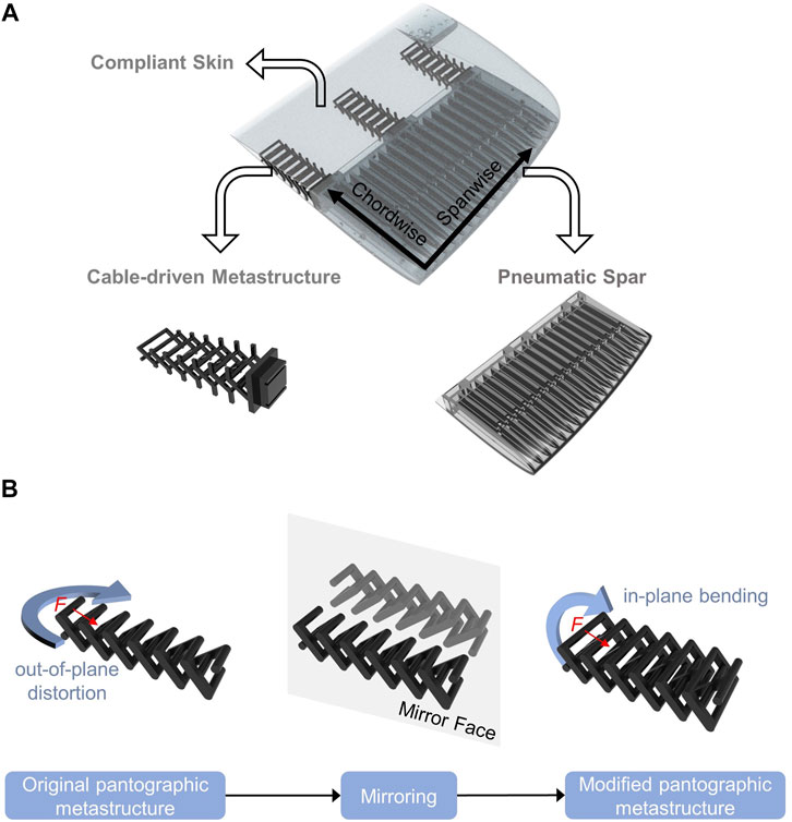
FIGURE 1. (A) Rendering of morphing wing composed of bidirectional SPAs and modified pantographic metastructure; (B) Original pantographic metastructure and modified one.
The trailing-edge is built by three modified pantographic ribs seamlessly covered by a layer of soft skin with the same material as the spar. The ribs are jointed with the pneumatic spar by adhesives. Legacy configuration of pantographic metamaterial is asymmetric, and out-of-plane distortion occurs when a side force is applied. Thus, a new pantographic structure is proposed in this work by adding a mirroring portion, as shown in Figure 1B. As a mechanical metastructure, this pantographic structure possesses anisotropic stiffness property (Dell’ Isola et al., 2019). It is flexible chordwise but stiffer spanwise. This property may meet the requirements of both stiffness to morph chordwisely and strength to bear aerodynamic loads. Overall, both continuous and smooth deformation are obtained along spanwise and chordwise directions.
In this paper, a platinum cured silicone, Dragon Skin 30 (produced by Smooth-On; http://www.smooth-on.com), was adopted for preparing SPAs and flexible skin of the morphing wing. Its fracture strain is up to 364%. As a silicone rubber, its mechanical behavior is typically hyperelastic, which is nonlinear in tension and nearly incompressible in compression. The constitutive model of hyperelastic material can be derived through a strain energy density function:
where
In this expression,
where
The Cauchy stress for the Yeoh model is given as:
For uniaxial elongation, there are:
By submitting Eq. 3 into Eq. 5, the function of stress-elongation can be derived. Uniaxial tensile tests were performed using dumbbell coupons at a rate of 500 mm/min. And test data were fitted to Yeoh model numerically. Finally,
The large deformation of modified pantographic metastructure comes from the accumulation of small elastic deformation out of each structural member. Thus, a resin material with high strength and toughness was used to fabricate pantographic ribs. Properties of the material are given in Table 1.
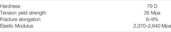
TABLE 1. Material properties of modified pantographic ribs.
Lost-Wax casting is a general method for duplicating metal products. This casting idea can be used as a fabrication process to manufacture fluidic elastomer actuators (Marchese et al., 2015). In this work, molds for casting elastomeric components of the morphing wing are divided into two types, including both resin and wax molds. Resin molds are used for molding exterior shape of the morphing wing and can be prepared by 3D printer. Wax molds, made of paraffin wax with low melting point, can change phases from solid to liquid at around 70°C. It is used to fabricate wax products forming inner channels of SPAs. After the elastomer is cured, the whole part is put into the oven. The wax is melted into fluid and flowed out through the molded channels. This process realizes an integrated manufacturing with good airtightness and produces good quality of wing surfaces.
The manufacturing process of pneumatic spar and skin is depicted in Figure 2A. Firstly, Part A and Part B of silicones are taken 1:1 by weight and mixed thoroughly for 3 min in a mix container. Secondly, the liquid mixture is poured into resin molds and vacuum degassing is adopted to eliminate the trapped air in the mixture. After 15 min of vacuum, the wax mold is inserted into liquid rubber slowly. Resin molds are designed with grooves to position the wax mold. Then the whole molds are placed in a thermostatic container. The whole part is cured fully at 30°C for 16 h at first. Then bake at 100°C for 30 min to let the wax melt.
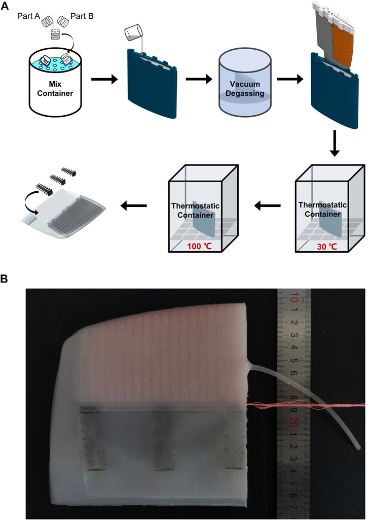
FIGURE 2. (A) Molding process of spar and skin; (B) A fabricated prototype of the morphing wing.
Three modified pantographic ribs were manufactured by 3D printer. They are inserted into the trailing edge section and glued onto the skin and spar with adhesives. A fabricated prototype of the morphing wing is shown in Figure 2B.
To simplify analytical modeling, it’s assumed that the change of height along chordwise is small and negligible. Then the actuator can be treated as a cuboid structure. The 3D model and cross-section view of the pneumatic actuator are shown in Figure 3. Taking nonlinearity and incompressibility into consideration, relationship among structural parameters, air pressure, and deflecting angle of elastomeric actuator is derived based on the energy principle.
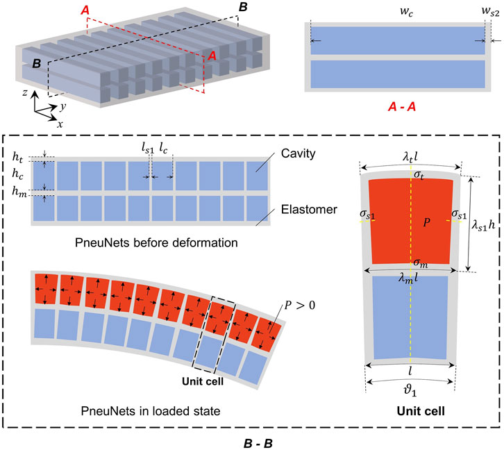
FIGURE 3. 3D and cross-section view of pneumatic spar with cuboid chambers. Red color denotes the pressurized chambers, and blue color denotes the unpressurized chambers.
The bending of the actuator is caused by different stretching extent of walls in the unit cell, and it’s assumed that the actuator bends curvedly by pressurizing upper chambers and unpressurizing lower chambers, and vice versa. The bottom wall is assumed to be bended and its length remains unchanged. Strain energy of a loaded bidirectional spar with PneuNets can be decomposed as:
In this expression,
Other geometric dimensions of a unit cell of the actuator are illustrated in Figure 3. Length and width of cavity are denoted by
where
According to the force equilibrium for longitudinal and transverse sections (presented by yellow dash line in B-B section in Figure 3), there is:
Small deformation assumption is adopted here to linearize the nonlinearity of hyperelastic material. Combining two equations in Eq. 8.1, relationship between stress of the side wall separating chambers and top wall is calculated as:
Then according to Eq. 8.2, relation between stretch ratio of the side wall separating chambers and top wall is given as:
where
Combining Eq. 7 and Eq. 8.3 into Eq. 6, each term of strain energy is represented as:
In this expression,
Due to incompressibility, the volume of hyperelastic material remains unchanged during deformation. Thus, volume of pressurized cavity can be approximated by:
where
According to the principle of virtual work:
Analytical relation between applied pressure
The cumulative bending angle of actuators with
The above equations can be used to calculate air pressure
The modified pantographic structure is created by an array of repeated unit cells. As shown in Figure 4A, each unit is composed of three staggered rectangular shafts (grey) connected by cylindrical shafts (blue and black). When a torque
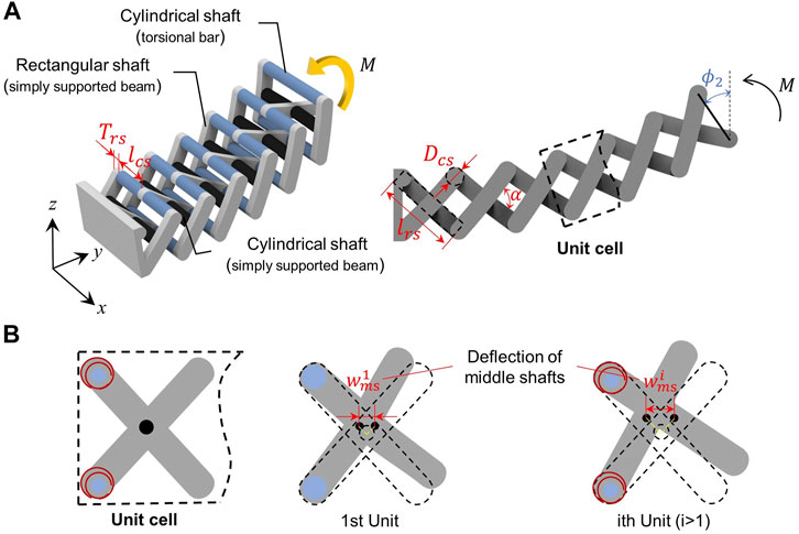
FIGURE 4. Rib with modified pantographic metastructure. (A) Illustration and geometric definition of modified pantographic metastructure composed of repeated unit cells; (B) Deflection of black shafts induced by bending (for the first unit cell) and rigid body rotation (for the
Firstly, in order to model its deformation theoretically, three assumptions are made as follows:
(1) Only torsion and pure bending occur in structural members under the action of external torque
(2) Simple stress states are assumed in structural members. Blue cylindrical shafts are torsional bars. Grey rectangular shafts and black cylindrical shafts are treated as beams under pure bending;
(3) Deformation of torsional shafts is consistent in each unit cell.
Under these assumptions, the loading-deflection behavior of pantographic rib is derived as follows. Considering the left end of the overall structure is fixed, there is no torsion of blue shafts in the first unit. The ends of black shafts are located at the midpoint of two adjacent grey shafts. Thus, black shafts deflect when projections of the midpoints on y-z plane are eccentric. It should be noted that shifts of the midpoints are induced by bending of grey shafts or torsion of blue shafts, as shown in Figure 4B. In the first unit, deflection
where
As for
where
On account of structural configuration, torque acting on middle rectangular shaft is twice of the one acting on two side rectangular shafts. Assumed as pure bending beams, deflection angle of grey rectangular shafts can be calculated as follows:
In this expression,
The minimum theory of potential energy is used to derive governing equations. The advantage is that energy approach disregards the deformation history and is only related to the deformed state. For a tortional bar, strain energy
where
For purely bending beam with a centering angle
where
Combining Eqs 13.1, 13.2, 14, 15.1, 15.2, total strain energy of a cell unit including two torsional bars (except for the first unit cell), four bending shafts can be obtained. The potential energy
where
As for
Bending angle of a modified pantographic metamaterial with n unit cells is:
In this paper, FEM is used to verify the validity of analytical model and predict the actuating performance of morphing wings. Hyperelastic behaviors of compliant skin and the pneumatic spar are characterized by Yeoh model. The pneumatic spar, stiffening ribs, and skin are discretized by solid elements. In this section, both ends of pneumatic spar and modified pantographic metastructure are fixed as cantilevered beams. The pressure and moment loading are applied respectively. These two parts are modeled individually for the purpose of model verification. The skin is not considered here, but in Section 5.1.
The 3D FEM of pneumatic spar and a modified pantographic metastructure were built with a set of parameters respectively to verify the accuracy of derived functions. The models are shown in Figure 5A. Pressure is applied on all internal faces of pressurized chambers to simulate inflation of SPAs. Torque loading is applied to the cantilevered end of the modified pantographic metastructure. Firstly, for SPAs, the dimensional parameters were chosen as
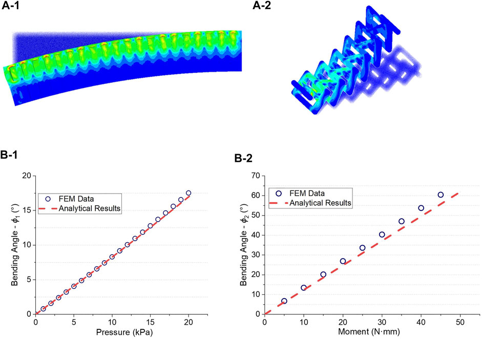
FIGURE 5. Analytical model validation by FEM. (A-1) FEM result of a deformed pneumatic spar and (A-2) FEM result of a pantographic rib; Curves of bending angle respecting to external loads along (B-1) spanwise and (B-2) chordwise (Broken red line: analytical model, blue circles: numerical results).
Secondly, for modified pantographic metastructure, the dimensional parameters were chosen as
In Section 3, relations between structural parameters and actuating loads are established. There are a dozen parameters associated with the analytical model. Therefore, orthogonal experiment of DOE is adopted in this paper to identify critical parameters among multiple factors (Xia et al., 2016).
For compliant spar with PneuNets, wall thicknesses, dimensions of chambers, and thickness of middle layer may impact actuating performance. The overall height of the actuator and chamber height are limited by airfoil dimensions and their effects are first disregarded. Thus, length of cavity
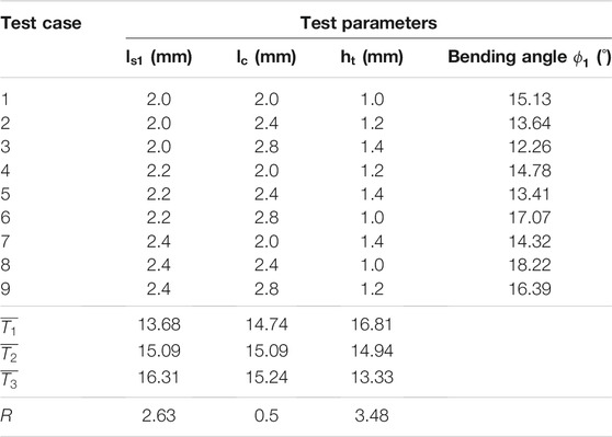
TABLE 2. Orthogonal experiment of structural parameters in a pneumatic spar.
As for modified pantographic ribs, dimensions of shafts and angle between staggered rectangular shafts have effects on actuating performance. Similarly, orthogonal experiment was designed to study the sensitivity of these parameters on the behavior of ribs. According to analytical model, five structural parameters including

TABLE 3. Orthogonal experiment of structural parameters in a pantographic rib.
The results show that effects of
Orthogonal experiments investigate the effect intendency of structural parameters on morphing mechanism and provide guidance for further optimization. Parametric studies with FEM were also conducted as a validation purpose and for structural optimization. The simulation results are shown in Figure 6. Loading condition similar with the model used for theorical validation was applied to pneumatic spar. While the pantographic rib is actuated by cables in practice, an equivalent force loading to torque was used to plot the curves in Figure 6B for experimental correlation.
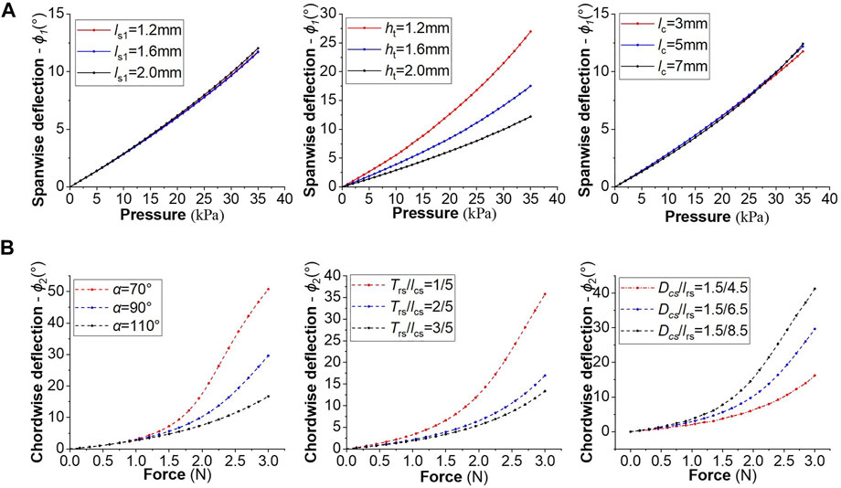
FIGURE 6. Design optimization of spar and ribs by FEM. (A) Spanwise bending angle of spar corresponding to different applied pressures; (B) Chordwise deflection of ribs corresponding to different applied cable forces.
As can be seen from Figure 6A,
The prototype was fabricated based on the referenced parameters from design optimization. The pneumatic spar contained 18 unit cells. The upper chamber and lower chamber were separated by a middle layer with thickness of 1.5 mm. Each cavity was 5 mm in length and about 6 mm in height. The thickness of top wall
The experimental setup to verify actuating performance of manufactured prototype is shown in Figures 7A-1,A-2. The morphing wing was clamped on one end and air pressure was supplied through a hand pump. The inner pressure is monitored and measured by a digital differential pressure gauge. Besides, tail end of each modified pantographic rib is tied with a fishing wire. The other end of three fishing lines is attached to a force gauge for calibration. A protractor is utilized to measure bending angles of morphing wings along spanwise and chordwise.
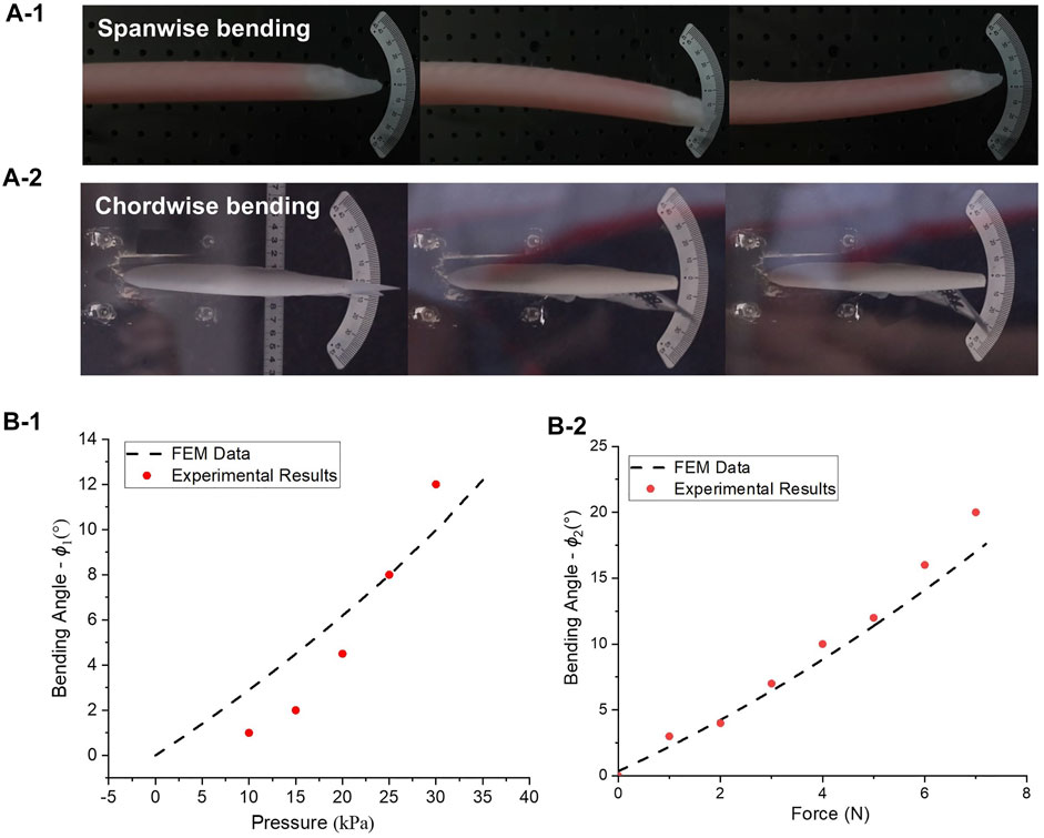
FIGURE 7. Experiments and FEM validation. (A-1) Spanwise deflection of morphing wings under pressure; (A-2) Chordwise deflection of morphing wings under force; (B-1) Comparison of spanwise deflection between FEM and experimental results under pressure control in a pneumatic spar; (B-2) Comparison of chordwise deflection between FEM and experimental results under force control in a pantographic rib (Red dots: experimental data, black dashed curves: FEM results).
As shown in Figures 7B–1,B-2, both bending angle
At last, a wind tunnel test with a Particle Image Velocimetry (PIV) instrument was conducted to examine load bearing capacity and dynamic response of the morphing wing in air-flow field. PIV is an optical method to visualize flow field. It can map the flow field and provide physical insight into flow behaviour (Atkins, 2016). The morphing wing may deflect in two directions. Spanwise morphing may improve lateral stability and maneuverability of the aircraft (Abdulrahim and Lind, 2004; Geva et al., 2019). Therefore, it was not considered in this test. As shown in Figure 8A, a test setup was built to focus on the evaluation of trailing-edge bending on aerodynamic layout through tunnel tests.
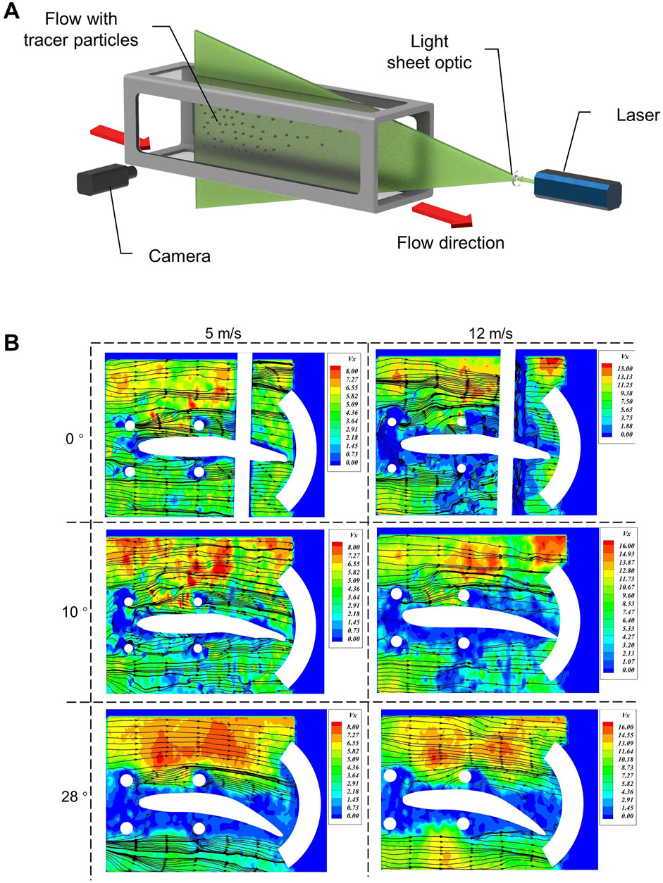
FIGURE 8. Wind tunnel test to determine load bearing capacity and aerodynamic response of morphing wings. (A) A wind tunnel test setup with a PIV instrument; (B) Airflow velocity contours near morphing wing at different air-flow speeds and specific chordwise angles.
Firstly, maximum load bearing capacity of the morphing wing was tested. It’s observed that obvious torsional instability of morphing wing happened when wind speed was beyond 13 m/s. To inflate internal cavities may increase the stiffness in elastomeric membranes. After being pressurized in pneumatic spar above 10 kPa, the maximum wind velocity that morphing wing can bear increased from 13 to 16 m/s.
As shown in Figure 8B, airflow velocity contours near morphing wing at different air-flow speeds and specific chordwise angles are demonstrated. It can be qualitatively observed that flow velocity field above the wing accelerated with deflection angle of trailing-edge increasing.
When the velocity of wind reaches 12 m/s, the morphing wing is still effective, but the aeroelastic fluttering of soft skin occurs. It may induce the local turbulence effect, which is a common issue in the compliant-skin design. It may be improved by the pre-tensioned technique (Muhammed, 2020).
This work developed a novel design of morphing wing to produce smooth and continuous deformation during shape changing. A new compliant structural architecture composed of pneumatic spar, cable driven ribs, and soft skins was described. Pneumatic spar based on PneuNets is used to achieve bending along wing span and modified pantographic ribs are used to control trailing-edge morphing. Large deflection of both longitudinal spar and chordwise ribs are realized through the microscopic design with metastructural type of unit cells. Analytical models of two basic units were derived and verified through FEM. Sensitivities of structural parameters on actuating performance were investigated by DOE methodology. With optimal combination of parameters, a prototype was manufactured through Lost-Wax casting. A series of experiments including a wind tunnel test were conducted. The results show that this morphing wing can achieve ±12° deflection along spanwise and ±35° deflection of trailing-edge. The reliable deformability of the wing was verified by wind tunnel test and it’s shown that this morphing wing can tune aerodynamic performance qualitatively. With advantages of lightweight, tunable stiffness and large morphing range, the novel design concept provides a feasible solution for small-scale aircraft with morphing wings.
The raw data supporting the conclusion of this article will be made available by the authors, without undue reservation.
LX: Investigation, Methodology, Validation, Software, Visualization, Writing—original draft; HZ: Conceptualization, Project administration, Methodology, Resources, Writing—review and editing; ZX: Methodology, Software, Validation; XL: Validation, Visualization, Software; CS: Validation, Visualization; KW: Resources, Validation, Visualization, Methodology, Writing—review and editing; LZ: Methodology, Resources.
The authors declare that the research was conducted in the absence of any commercial or financial relationships that could be construed as a potential conflict of interest.
All claims expressed in this article are solely those of the authors and do not necessarily represent those of their affiliated organizations, or those of the publisher, the editors, and the reviewers. Any product that may be evaluated in this article, or claim that may be made by its manufacturer, is not guaranteed or endorsed by the publisher.
Abdulrahim, M., and Lind, R. (2004). “Flight Testing and Response Characteristics of a Variable Gull-Wing Morphing Aircraft,” in AIAA guidance, navigation, and control conference and exhibit, Providence, Rhode Island, August 16–19, 2004, 5113. doi:10.2514/6.2004-5113
Ahmed, M. R., Abdelrahman, M. M., ElBayoumi, G. M., and ElNomrossy, M. M. (2011). Optimal Wing Twist Distribution for Roll Control of MAVs. Aeronaut. J. 115 (1172), 641–649. doi:10.1017/S0001924000006333
Ali, A., Hosseini, M., and Sahari, B. B. (2010). A Review of Constitutive Models for Rubber-Like Materials. Am. J. Eng. Appl. Sci. 3 (1), 232–239. doi:10.3844/ajeassp.2010.232.239
Arruda, E. M., and Boyce, M. C. (1993). A Three-Dimensional Constitutive Model for the Large Stretch Behavior of Rubber Elastic Materials. J. Mech. Phys. Sol. 41 (2), 389–412. doi:10.1016/0022-5096(93)90013-6
Atkins, M. D. (2016). “Velocity Field Measurement Using Particle Image Velocimetry (PIV),” in Application of Thermo-Fluidic Measurement Techniques. Editors T. Kim, T Lu, and S.J. Song (New York, USA: Butterworth-Heinemann), 125–166. doi:10.1016/b978-0-12-809731-1.00005-8
Barbarino, S., Bilgen, O., Ajaj, R. M., Friswell, M. I., and Inman, D. J. (2011). A Review of Morphing Aircraft. J. Intell. Mater. Syst. Structures 22 (9), 823–877. doi:10.1177/1045389X11414084
Bilgen, O., Kochersberger, K., Diggs, E., Kurdila, A., and Inman, D. (2007). “Morphing Wing Micro-Air-Vehicles via Macro-Fiber-Composite Actuators,” in 48th AIAA/ASME/ASCE/AHS/ASC Structures, Structural Dynamics, and Materials Conference, 1785, Honolulu, Hawaii, April 23–26, 2007. doi:10.2514/6.2007-1785
Chen, Y., Zhao, H., Mao, J., Chirarattananon, P., Helbling, E. F., Hyun, N.-S. P., et al. (2019). Controlled Flight of a Microrobot Powered by Soft Artificial Muscles. Nature 575 (7782), 324–329. doi:10.1038/s41586-019-1737-7
Cui, T. J., Smith, D. R., and Liu, R. (2010). Metamaterials: Theory, Design, and Applications. New York: Springer US.
Davis, W. R., Kosicki, B. B., Boroson, D. M., and Kostishack, D. E. (1996). Micro Air Vehicles for Optical Surveillance. Lincoln Lab. J. 9 (2), 197–214.
Dell’ Isola, F., Seppecher, P., Alibert, J. J., Lekszycki, T., Grygoruk, R., Pawlikowski, M., et al. (2019). Pantographic Metamaterials: An Example of Mathematically Driven Design and of its Technological Challenges. Continuum Mech. Thermodyn. 31 (4), 851–884. doi:10.1007/s00161-018-0689-8
Dell’Isola, F., Giorgio, I., Pawlikowski, M., and Rizzi, N. L. (2016). Large Deformations of Planar Extensible Beams and Pantographic Lattices: Heuristic Homogenization, Experimental and Numerical Examples of Equilibrium. Proc. R. Soc. A. 472 (2185), 20150790. doi:10.1098/rspa.2015.0790
Di Luca, M., Mintchev, S., Heitz, G., Noca, F., and Floreano, D. (2017). Bioinspired Morphing Wings for Extended Flight Envelope and Roll Control of Small Drones. Interf. Focus. 7 (1), 20160092. doi:10.1098/rsfs.2016.0092
Ettinger, S. M., Nechyba, M. C., Ifju, P. G., and Waszak, M. (2003). Vision-Guided Flight Stability and Control for Micro Air Vehicles. Adv. Robotics 17 (7), 617–640. doi:10.1163/156855303769156983
Galiński, C., and Żbikowski, R. (2007). Some Problems of Micro Air Vehicles Development. Bull. Polish Acad. Sci. Tech. Sci. 55 (1), 91–98. Available at: https://journals.pan.pl/dlibra/publication/127427/edition/111183/content
Geva, A., Abramovich, H., and Arieli, R. (2019). Investigation of a Morphing Wing Capable of Airfoil and Span Adjustment Using a Retractable Folding Mechanism. Aerospace 6 (8), 85. doi:10.3390/aerospace6080085
Graule, M. A., Chirarattananon, P., Fuller, S. B., Jafferis, N. T., Ma, K. Y., Spenko, M., et al. (2016). Perching and Takeoff of a Robotic Insect on Overhangs Using Switchable Electrostatic Adhesion. Science 352 (6288), 978–982. doi:10.1126/science.aaf1092
Harne, R. L., Wu, Z., and Wang, K. W. (2016). Designing and Harnessing the Metastable States of a Modular Metastructure for Programmable Mechanical Properties Adaptation. J. Mech. Des. 138 (2), 021402. doi:10.1115/1.4032093
Ifju, P., Jenkins, D., Ettinger, S., Lian, Y., Shyy, W., and Waszak, M. (2002). “Flexible-wing-based Micro Air Vehicles,” in 40th AIAA Aerospace Sciences Meeting & Exhibit, Reno, NV, January 14–17, 2002, 705. doi:10.2514/6.2002-705
Ilievski, F., Mazzeo, A. D., Shepherd, R. F., Chen, X., and Whitesides, G. M. (2011). Soft Robotics for Chemists. Angew. Chem. 123 (8), 1930–1935. doi:10.1002/ange.201006464
Joo, J. J., Marks, C. R., and Zientarski, L. (2015). “Active wing Shape Reconfiguration Using a Variable Camber Compliant wing System,” in 20th International Conference on Composite Materials, Copenhagen, Denmark, July 19–24, 2015, 19–24.
Lian, Y. (2009). “Numerical Study of a Flapping Airfoil in Gusty Environments,” in 27th AIAA Applied Aerodynamics Conference, San Antonio, Texas, June 22–25, 2009, 3952. doi:10.2514/6.2009-3952
Marchese, A. D., Katzschmann, R. K., and Rus, D. (2015). A Recipe for Soft Fluidic Elastomer Robots. Soft robotics 2 (1), 7–25. doi:10.1089/soro.2014.0022
Meguid, S. A., Su, Y., and Wang, Y. (2017). Complete Morphing Wing Design Using Flexible-Rib System. Int. J. Mech. Mater. Des. 13 (1), 159–171. doi:10.1007/s10999-015-9323-0
Mosadegh, B., Polygerinos, P., Keplinger, C., Wennstedt, S., Shepherd, R. F., Gupta, U., et al. (2014). Pneumatic Networks for Soft Robotics that Actuate Rapidly. Adv. Funct. Mater. 24 (15), 2163–2170. doi:10.1002/adfm.201303288
Parancheerivilakkathil, M. S., Ajaj, R. M., and Khan, K. A. (2020). A Compliant Polymorphing Wing for Small UAVs. Chin. J. Aeronautics 33 (10), 2575–2588. doi:10.1016/j.cja.2020.03.027
Pérez-Arancibia, N. O., Ma, K. Y., Galloway, K. C., Greenberg, J. D., and Wood, R. J. (2011). First Controlled Vertical Flight of a Biologically Inspired Microrobot. Bioinspir. Biomim. 6 (3), 036009. doi:10.1088/1748-3182/6/3/036009
Polygerinos, P., Lyne, S., Zheng, Z., Nicolini, L. F., Mosadegh, B., Whitesides, G. M., et al. (2013). “Towards a Soft Pneumatic Glove for Hand Rehabilitation,” in 2013 IEEE/RSJ International Conference on Intelligent Robots and Systems, Tokyo, Japan, November 3–7, 2013, 1512–1517. doi:10.1109/IROS.2013.6696549
Polygerinos, P., Wang, Z., Overvelde, J. T. B., Galloway, K. C., Wood, R. J., Bertoldi, K., et al. (2015). Modeling of Soft Fiber-Reinforced Bending Actuators. IEEE Trans. Robot. 31 (3), 778–789. doi:10.1109/TRO.2015.2428504
Saeed, N. M., and Kwan, A. S. K. (2014). Concepts for Morphing Aerofoil Sections Using Pantographic Structures. Mobile and Rapidly Assembled Structures IV 136, 279. doi:10.2495/MAR140231
Seppecher, P., Spagnuolo, M., Barchiesi, E., Hild, F., Lekszycki, T., Giorgio, I., et al. (2019). Advances in Pantographic Structures: Design, Manufacturing, Models, Experiments and Image Analyses. Continuum Mech. Thermodyn. 31 (4), 1231–1282. doi:10.1007/s00161-019-00806-x
Shepherd, R. F., Ilievski, F., Choi, W., Morin, S. A., Stokes, A. A., Mazzeo, A. D., et al. (2011). Multigait Soft Robot. Proc. Natl. Acad. Sci. 108 (51), 20400–20403. doi:10.1073/pnas.1116564108
Shyy, W., Lian, Y., Tang, J., Liu, H., Trizila, P., Stanford, B., et al. (2008). Computational Aerodynamics of Low Reynolds Number Plunging, Pitching and Flexible Wings for MAV Applications. Acta Mech. Sin 24 (4), 351–373. doi:10.1007/s10409-008-0164-z
Suzumori, K., Endo, S., Kanda, T., Kato, N., and Suzuki, H. (2007). “A Bending Pneumatic Rubber Actuator Realizing Soft-Bodied Manta Swimming Robot,” in 2007 IEEE international conference on robotics and automation, Rome, Italy, April 10–14, 2007, 4975–4980. doi:10.1109/ROBOT.2007.364246
Vos, R., Barrett, R., Breuker, R. d., and Tiso, P. (2007). Post-buckled Precompressed Elements: A New Class of Control Actuators for Morphing wing UAVs. Smart Mater. Struct. 16 (3), 919–926. doi:10.1088/0964-1726/16/3/042
Wang, F., Liang, Y., Li, X., Li, L., Li, J., and Chen, Y. (2019). Orthogonal Experimental Study on Multifactor Conditions for Gas Desorption in Coal. Adv. Civil Eng. 2019, 1–12. doi:10.1155/2019/3028721
Ward, T. A., Fearday, C. J., Salami, E., and Binti Soin, N. (2017). A Bibliometric Review of Progress in Micro Air Vehicle Research. Int. J. Micro Air Vehicles 9 (2), 146–165. doi:10.1177/1756829316670671
Xia, S., Lin, R., Cui, X., and Shan, J. (2016). The Application of Orthogonal Test Method in the Parameters Optimization of PEMFC under Steady Working Condition. Int. J. Hydrogen Energ. 41 (26), 11380–11390. doi:10.1016/j.ijhydene.2016.04.140
Yi Sun, Y., Yun Seong Song, Y. S., and Paik, J. (2013). “Characterization of Silicone Rubber Based Soft Pneumatic Actuators,” in IEEE/RSJ International Conference on Intelligent Robots and Systems, Tokyo, Japan, November 3–7, 2013, 4446–4453. doi:10.1109/IROS.2013.6696995
Keywords: micro air vehicles (MAVs), morphing wing, pneumatic networks, hyperelastic materials, metastructures with tunable stiffness
Citation: Xiao L, Zhao H, Xu Z, Li X, Shen C, Wang K and Zhang L (2022) A New Architecture of Morphing Wing Based on Hyperelastic Materials and Metastructures With Tunable Stiffness. Front. Mech. Eng 7:814446. doi: 10.3389/fmech.2021.814446
Received: 13 November 2021; Accepted: 16 December 2021;
Published: 09 February 2022.
Edited by:
Xin-Lin Gao, Southern Methodist University, United StatesReviewed by:
Yongqiang Li, Nanjing University of Aeronautics and Astronautics, ChinaCopyright © 2022 Xiao, Zhao, Xu, Li, Shen, Wang and Zhang. This is an open-access article distributed under the terms of the Creative Commons Attribution License (CC BY). The use, distribution or reproduction in other forums is permitted, provided the original author(s) and the copyright owner(s) are credited and that the original publication in this journal is cited, in accordance with accepted academic practice. No use, distribution or reproduction is permitted which does not comply with these terms.
*Correspondence: Haifeng Zhao, aGZ6aGFvQGNzdS5hYy5jbg==; Ke Wang, d2FuZ2tlQGNzdS5hYy5jbg==
Disclaimer: All claims expressed in this article are solely those of the authors and do not necessarily represent those of their affiliated organizations, or those of the publisher, the editors and the reviewers. Any product that may be evaluated in this article or claim that may be made by its manufacturer is not guaranteed or endorsed by the publisher.
Research integrity at Frontiers
Learn more about the work of our research integrity team to safeguard the quality of each article we publish.