 Shijie Bai
 Hongsheng Zhang
 Chang Li1
 Kun Wang
95% of researchers rate our articles as excellent or good
Learn more about the work of our research integrity team to safeguard the quality of each article we publish.
Find out more
ORIGINAL RESEARCH article
Front. Mech. Eng. , 13 January 2022
Sec. Engine and Automotive Engineering
Volume 7 - 2021 | https://doi.org/10.3389/fmech.2021.743342
This article is part of the Research Topic Particulate Matter Emissions from Conventional and Reformulated Fuel Combustion: Advances in Experiments and Simulations View all 9 articles
The primary objective of the present study was to investigate the impact of wall film on the combustion characteristics of premixed flames in internal combustion engines through the joint experimental and numerical techniques. The interaction between the premixed methane-air flame and n-dodecane film attached to the wall of a constant volume combustion bomb was experimentally examined. The flame propagation processes, as well as pressure evolution were quantitatively characterized. Then, computational fluid dynamic (CFD) simulation was performed incorporating the combustion chemistry model. To enable efficient simulation of the chemically reacting flow in engine chambers, a simplified modeling approach based on a two-step reaction scheme was developed. A compact reaction model for the selected model fuel n-dodecane was constructed and reduced to include 35 chemical species and 180 reactions. The flame propagation process of the premixed flame and its interaction with dry and wet walls was studied. The results showed that the propagation of the premixed flame could be divided into four stages, and the existence of the slit structure increased the instability of the flame structure in the near-wall region. The wall film tended to promote emissions, producing more unburned hydrocarbons, soot precursors and aldehydes.
Direct injection engines are rapidly dominating the engine market due to the higher compression ratio, increased thermal efficiency and fuel economy. For small and medium-sized high-speed direct injection diesel engines, the fuel spray is likely to collide with the wall of the combustion chamber to form a wall-mounted film due to the limitation of the combustion chamber geometry (Brandriss et al., 1998; Zhao et al., 1999; Shim et al., 2009; Zhang et al., 2016). In particular, during the engine cold start, or at low speed and high load conditions with a large amount of fuel being injected, under which conditions, the evaporation of fuel spray is reduced, which forms a liquid film on the surface of the piston or cylinder liner, resulting in the “wet wall” phenomenon. Meanwhile, in order to further reduce emissions and improve fuel efficiency, early injection technology has been widely used, through which injection strategy, part of the fuel is injected into the cylinder early in the compression stroke. At this moment, the temperature and pressure inside the cylinder are relatively low and the evaporation rate slows down, which increases the spray penetration distance in the cylinder chamber. This may also lead substantial amount of liquid fuel attaching the cylinder liner surface, forming wet wall phenomenon (Kook et al., 2008; Benajes et al., 2012; Yu et al., 2017; Huang et al., 2019). The above engine scenarios lead to an inevitable interaction between the engine combustion flame and the wall liquid fuel film, which may notably impact the engine combustion as well as emission characteristics, including variation of flame development/propagation, quenching distance, and wall heat flux, as well as elevated production of aldehydes, particulate matters (PM), and unburned hydrocarbons (UHC) (Benajes et al., 2012; Dreizler and Böhm, 2015; Liu et al., 2015; Tang et al., 2017). Fundamental studies on the effect of fuel film on premixed flame combustion and emissions characteristics can help optimize the design of diesel engine combustion systems, improve in-cylinder combustion processes, increase engine thermal efficiency, and reduce emissions.
The main factors that impact the flame quenching process or change the quenching distance are the heat loss in the form of conduction and radiation between the flame and the wall. Due to heat losses, the temperature of the flame front surface drop rapidly once it reaches the wall, meanwhile the active chemical free radicals in the flame are rapidly annihilated. The consequence from the above joint effects is the interruption of the combustion chemical chain branching and chain propagation reactions, which eventually lead to flame quenching in the near-wall region (Poinsot et al., 1993; Foucher et al., 2003; Kim et al., 2008; Bai et al., 2013; Bohlin et al., 2016; Gauthier and Bergthorson, 2016). When the quenching phenomenon occurs, a layer of unburned fuel components or combustible mixture that has not been completely burned remain in the near-wall area. Therefore, it contained high levels of UHC, carbon monoxide (CO), aldehydes and other species (Li et al., 2010; Najim et al., 2015). Sotton et al. (Sotton et al., 2005) investigated the effect of interaction between methane-air laminar flame and wall on quenching distance and wall heat flux in the pressure range of 0.05–1.7 MPa under dry wall condition, in which study the relationship between the maximum heat flux peak and the flame quenching distance was examined. Yenerdag et al. (Yenerdag et al., 2017) found that the flame quenching distance was directly related to the wall temperature, where the peak heat flow density at the wall was the key factor affecting the quenching distance, through the utilization of a direct numerical simulation (DNS) method. Kim et al. (Kim et al., 2006) investigated the quenching process of a flame inside a flat plate in a two-dimensional slit burner and found that the wall temperature had a direct effect on the heat transfer losses of the flame-wall interaction process as well as the annihilation of wall radical chemistry.
Compared to dry wall condition, a wet wall with liquid fuel film impact the near-wall distribution of temperature and active chemical intermediates, which then control the flame propagation process. As the temperature in the combustion chamber increasing, to promote the vaporization of fuel components, the film surface tends to form a fuel-rich layered mixture (Kang and Kyritsis, 2005; Liu et al., 2011; Zhao et al., 2016; Lipatnikov, 2017). When the flame approaches the wall, the burning rate was determined by the stratification of the upstream gas mixture concentration (Qiao et al., 2005; Zhang and Abraham, 2016; Shi et al., 2017). Desoutter et al. (Desoutter et al., 2005) studied the interaction of a premixed flame with a 20 μm thick fuel film, using a one-step chemical reaction model incorporated in a one-dimensional numerical simulation, which revealed an increase in the flame quenching distance. The authors also tried to analyze the mechanism(s) leading to suppressed chemical reactions and heat loss during the quenching occurrence. Tao et al. (Tao et al., 2018; Tao et al., 2020) used a numerical simulation to investigate the effect of film on premixed flame propagation and emissions using iso-octane as the gasoline surrogate fuel.
As shown by the above analysis, the wet wall condition in the presence of fuel film made the flame-wall interaction process much more complicated than these of dry wall conditions. Therefore, the current understanding of the problem was primarily based on numerical simulation methods. Furthermore, the numerical simulation processes either used a minimalistic single-step reaction model or a single-component surrogate fuel to simulate the process of liquid fuel mixtures evaporating at the wall and participating in engine combustion. In the present study, the effect of fuel film on the combustion characteristics of premixed flames under both dry and wet wall conditions in a constant volume combustion bomb was investigated by using experimental and numerical methods. Firstly, the flame propagation and pressure evolution of the premixed methane-air mixtures were recorded or quantitively characterized in a constant volume combustion bomb. Secondly, a simplified modeling approach based on a two-step reaction scheme for describing the combustion reactions of large hydrocarbons was developed. Model reduction and validation of the reaction kinetic model was carried out to obtain a compact yet accurate reaction model for the CFD simulations. Finally, the effects of flame-wall interaction on the flame quenching, wall heat flux, exothermic rate and emissions during combustion were investigated in CFD simulations.
To investigate the effect of “wet wall” phenomenon on the flame propagation process of the premixed flame, a constant volume combustion bomb model with slit structure was developed. The setup of experiment and schematic diagram of the constant volume combustion bomb was shown in Figure 1. The experimental equipment included fuel supply and exhaust system, electronically-controlled ignition system, steady-state temperature and pressure sensors, constant temperature heating system, removable oil film impact wall plate structure, cylinder pressure collection and signal processing system, high-speed schlieren photography system, and electronical valve devices. A schlieren system with a Z-type arrangement was used to capture images of the flame propagation process. As shown in Figure 1, a light source, a slit, two concave mirrors, a knife and two flat mirrors were also included. Using a fixed-volume combustion system with a removable plate covered by fuel film, the effect of wet wall on premixed flame propagation characteristics was explored. A high-speed schlieren photography was used to visualize and record the flame propagation process and flame morphology, and a piezoelectric pressure transducer (Kistler 7061C type) combined with a charge amplifier (Kistler 5018 A type) was installed 8 mm from the bottom of the channel on the left side of the system (Zhang et al, 2021).
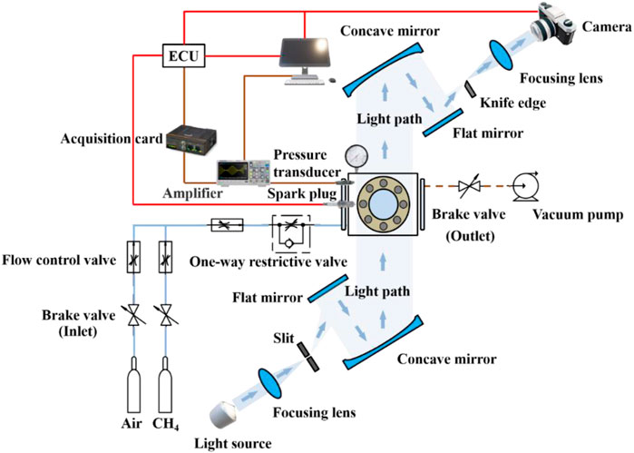
FIGURE 1. Experimental equipment of constant volume combustion bomb.
To perform the wet wall experiment, the end cover of the bomb was opened to place the fuel film plate. The film plate coated with uniform thickness of liquid fuel on the right wall surface of the combustion chamber, so that the wall surface of the slit side of the constant volume combustion bomb was diesel film. Under actual engine conditions, the wall film thickness might vary from a few microns to tens of microns due to the combined effect of gas phase heat transfer and cylinder wall heat transfer. To mimic the actual engine conditions, the initial thickness of the fuel film was controlled to be around 10 microns in the present study. A syringe was used to inject a small amount of liquid n-dodecane (volume V) onto the plate and swiped evenly by a short oil painting scraper. Table 1 listed the experimental parameters, under which concisions at least three sets of experiments were repeated with the averaged value reported.
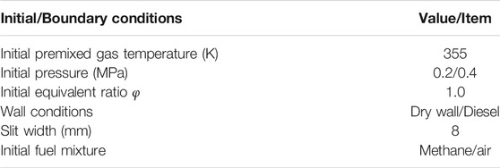
TABLE 1. Experimental parameters.
The initial oil film thickness distribution determined using an oil film thickness gauge. An initial film thickness close to 10 μm was achieved by using a fixed initial liquid fuel volume of 0.25 ml in each test. The oil film was applied evenly on a flat surface by using a short oil painting scraper, and then left for 60 s to obtain a uniform distribution of oil film thickness.
The establishment of a kinetic model that could accurately describe its combustion characteristics was essential to simulate the combustion reaction process of diesel engines, which was of great help to improve the engine combustion efficiency and reduce formation of pollutant emissions. However, the conventional detailed chemical reaction mechanisms might be too complicated to be incorporated into the computational fluid dynamic (CFD) simulations. The present study developed a simplified modeling method to concisely describe the high-temperature combustion chemistry of large hydrocarbons based on a two-step reaction scheme (TSRS) (Wang et al., 2019; Shen et al., 2021).
The two-step reaction scheme (TSRS) has been developed as a newly advanced simplified modeling approach with simplicity and accuracy. The two-step reaction scheme was developed based on the principle of the two-zone characteristic of high-temperature combustion. Current experimental and theoretical studies have shown that high-temperature combustion chemistry can be divided into two processes: pyrolysis and oxidation. The two-step reaction scheme described the pyrolysis process in terms of seven lumped reactions and the oxidation process in terms of a detailed foundational fuel model. Therefore, the model based on this approach was not only concise but also accurate.
The current common simplified modeling methods, such as the decoupling method, did not have advantages in model size and accuracy compared to TSRS. Moreover, in terms of model building process, other methods basically relied on detailed mechanism simplification and were limited by the existing research. In contrast, TSRS model building relied on the basic chemical reaction principles and molecular structure analysis. As long as the structural properties of the fuel molecules are clarified, the model could be developed by this method.
Specifically, the combustion reaction process of large hydrocarbons could be divided by two subsequent steps, driven by thermodynamics under high temperature conditions. The first step was the decomposition of the parent fuel into a group of intermediates, including ethylene, propylene, butene, methane, hydrogen, etc., which generally were ranging from C0-C4. The second step was the slower oxidation reactions of these decomposed products. Among the two reaction steps, the first step was much faster, thus the second step was the rate-limiting step of the entire reaction process, according to the quartz-steady state assumption. To concisely and accurately develop the reaction model, a seven-reaction sub-model was used to describe the reaction process of rapid conversion of the parent fuel into pyrolysis intermediates, while a detailed foundational fuel chemistry mechanism [e.g., USC mech II (Wang et al., 2007)] was used to describe the oxidation reactions of the decomposed products.
More specifically, as one typical fuel components for jet and diesel fuels, n-dodecane was used as applied as the fuel film in the present study. A simplified reaction model for n-dodecane was constructed based on the above two-step reaction scheme, with the seven-reaction simplified fuel-decomposition model listed in Table 2. Combined with the detailed foundational fuel chemistry mechanism, for which purpose, the USC mech II was selected, the entire reaction model contained 113 chemical species and 799 reactions. During the development of the reaction model, the kinetic parameters were obtained from (Klippenstein et al., 2006; Wang et al., 2015), and the thermodynamic data were estimated by group additivity method (Ritter and Bozzelli, 2010). The thus-developed kinetic model of n-dodecane was further reduced by directed relation graphs with error propagation (DRGEP) method. The final combustion reaction model used in the CFD simulations contained 74 species and 552 reactions. The validation of the original and reduced models was provided in the Results and Discussion section.
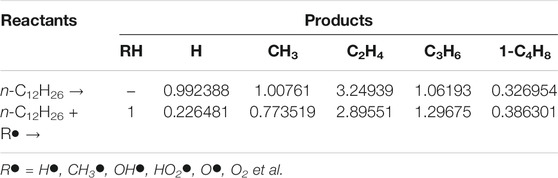
TABLE 2. The seven-reaction simplified fuel-decomposition model of n-dodecane.
In the present study, the geometric configuration of a three-dimensional constant volume combustion bomb with a slit structure was developed based on converge to investigate the effect of n-dodecane film on the propagation characteristics of methane-air premixed flame. The schematic diagram and computational domain of the 3-days constant volume combustion bomb was shown in Figure 2, which included an upper main combustion chamber and a closed narrow channel structure at the lower right. As shown in Figure 2, the entire interior of the cavity was uniformly filled with a premixed methane-air gas. The ignition source was located at the center of the left wall surface, 30 mm from the lower wall surface. A thickness of 0.01 mm n-dodecane film was placed on the right wall of the main combustion chamber. The ignition energy was set to 0.1 J for igniting the premixed methane-air mixture to generate the flame, which propagated through the chamber to the fuel film on the right wall. And then the total grid number was about 1.08 million.
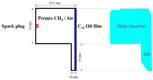
FIGURE 2. Left plot: Schematic of the methane-air mixture, ignition source and fuel film placed on the combustion chamber wall (2D model); Right plot: Schematic of the computational domain a cylindrical constant volume combustion bomb (3D model).
The liquid n-dodecane film was heated to evaporate rapidly into the gas phase to participate in the combustion reactions occurring in the chamber. Therefore, it was essentially a homogeneous reaction process in which the controlling equation for individual substance conservation was solved only in the gas phase, and the evaporation of the liquid film changed the source term. The equations for the flame-dry/wet wall interaction processes including the mass, momentum, energy and species conservation equations, were expressed as following:
Where ρ was density, u was velocity, p was pressure, σxx was the component of the viscous stress tensor in the x-direction, e was the internal energy, T was the temperature, Ym was the mass fraction of compound m, k was the thermal conductivity, Dm, mix was the diffusion coefficient of compound m, hm was the enthalpy of compound m. S, Se and Sm were all source terms; S was the mass changed due to the evaporation of the oil film, Se was the amount of energy change due to evaporation and chemical reaction of the liquid phase at the gas-liquid interface, Sm was the amount of change in the substance involved in the chemical reaction due to the evaporation of compound m.
Table 3 showed the physical models used for the simulation of the flame-wall interaction, which demonstrated the computational principles and solution process to investigate the flame-wall interaction. Specifically, the wall temperature model was chosen as a thermal conductivity model, where the wall temperature was kept constant during the reaction. In order to accurately and reasonably describe the complicated combustion reaction processes, the detailed chemical reaction kinetic solver SAGE was chosen for the combustion model. The RNG κ-ε turbulence model in RANS (Reynolds Averaged Navier-Stokes) was chosen for the turbulence model. To investigate the effect of wall film on emissions, the extended Zeldovich mechanism was chosen for the NOx generation mechanism (McGrawHill, 1988). For the soot model, a multi-step phenomenological model with polycyclic aromatic hydrocarbons PAH as soot precursors, namely the Gokul model proposed by Vishwanathan et al. (Vishwanathan and Reitz, 2010), was chosen. The soot model used pyrene (quadruple ring, A4) as the precursor, C2H2 as the surface growth component of the soot, and OH• and O2 as the key components of the soot oxidation process.
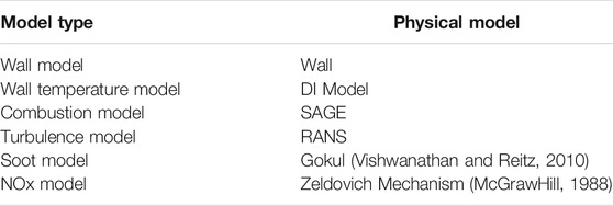
TABLE 3. CONVERGE models used in the simulations.
The initial/boundary conditions were varied in the constant volume conditions to investigate the wall film and premixed flame interactions and their effects on combustion characteristics and emissions, including temperature, pressure, wall temperature, film thickness, and initial equivalent ratio. The detailed settings were shown in Table 4.
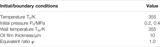
TABLE 4. Boundary condition settings.
There were in fact two reaction systems occurring during the flame-wet wall interaction process, e.g., the pre-mixed methane-air reaction system in the chamber and the vaporized n-dodecane fuel reaction system from the wet wall. Therefore, the developed kinetic model through the above simplified modeling approach needs to be validated by the data from the two reaction systems, respectively. As shown in Figures 3, 4, the methane and n-dodecane combustion chemistry model were validated, respectively. For the purpose of the application in the present study, the global combustion properties including the ignition delay time and laminar flame speed were used for the model validation. Furthermore, the developed kinetic model, though already very compact, was still subject for further reduction so as to efficiently be incorporated into CFD simulations. The well-established directed relation graph with error propagation (DRGEP) method was used to reduce the developed model. It could be seen from the figures that the predicted ignition delay time and laminar flame speed of methane and n-dodecane by the present detailed chemical kinetic mechanism and the reduced kinetic mechanism were in good agreement with the reported experimental values (Lifshitz et al., 1971; Zhu et al., 1989; Davidson et al., 2008; Ji et al., 2010).
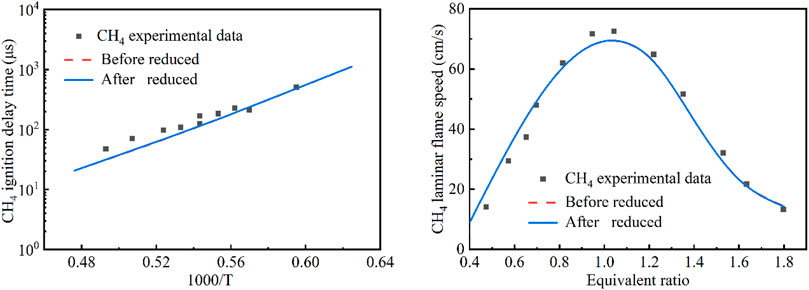
FIGURE 3. Comparison of the original and simplified models for the methane reaction system (Lifshitz et al., 1971; Zhu et al., 1989) (Red - original model; Blue - reduced model. Left plot: ignition delay time at p = 9 atm, 0.0212CH4 + 0.0212O2 + 0.9576AR; Right plot: laminar flame speed at T = 300 K, p = 1 atm).
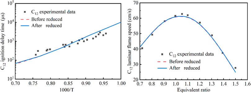
FIGURE 4. Comparison of the original and simplified models for the n-dodecane reaction system (Davidson et al., 2008; Ji et al., 2010) (Red - original model; Blue - reduced model. Left plot: ignition delay time at p = 6.7 atm, n-C12H26/21%O2 + AR, ϕ = 0.5; Right plot: laminar flame speed at T = 403 K, p = 1 atm).
The simplified mechanism model was then incorporated into the CFD simulation in the Converge software. Firstly, a grid-independent analysis of the computational results was carried out to ensure that the selected grid size had no or negligible impact on the simulation results. As shown in Figure 5, the grid size was set to 1 mm, and three embedded encryption levels were selected for the grid refinement of the near-wall area around the oil film on the left side, which were 0.5, 0.25 and 0.125 mm, respectively. In addition, a comparison of the simulated and experimental pressure values was also performed as shown in Figure 5. The variation of pressure in the combustion chamber were almost the same when using the secondary and tertiary encryptions. Therefore, on the basis of balancing computational accuracy and computational efficiency, the grid size was set to 1 mm with two-level adaptive grid encryption based on temperature, velocity, and hydroxyl radical (OH•) concentration. In addition, the near-wall area around the oil film on the left side was encrypted with a two-stage embedding with a grid size of 0.25 mm, which could accurately capture the subtle characteristics of the heat and mass transfer processes, as well as the flame propagation toward the wall around the oil film.
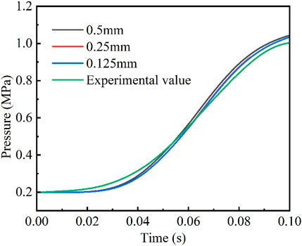
FIGURE 5. Grid-independent analysis of the combustion chamber pressure.
The combustion and propagation processes of the premixed flame in the engine combustion chamber were critical for improving the thermal efficiency of the engine and optimizing the engine structure. In the present study, experimental and numerical simulations were jointly developed to investigate the propagation of premixed flames within the slit in a confined space and their interaction with dry and wet walls under different initial pressures. Figures 6, 7 showed the propagation of the methane-air premixed flame in the constant-volume combustion chamber at an initial pressure of 0.2 MPa, with and without a thin lay of n-dodecane film on the right-side wall, which was corresponding to the wet and dry wall, respectively. In the both figures, the upper plots were the image obtained from the high-speed schlieren photography during the combustion chamber experiment, while the lower plots were the images of the flame propagation process obtained from the numerical simulation after digital post-processing. The comparison of these images between experiment and simulation for the recorded combustion process showed that the numerical simulation reproduced well the flame characteristics of the methane-air premixed combustion.
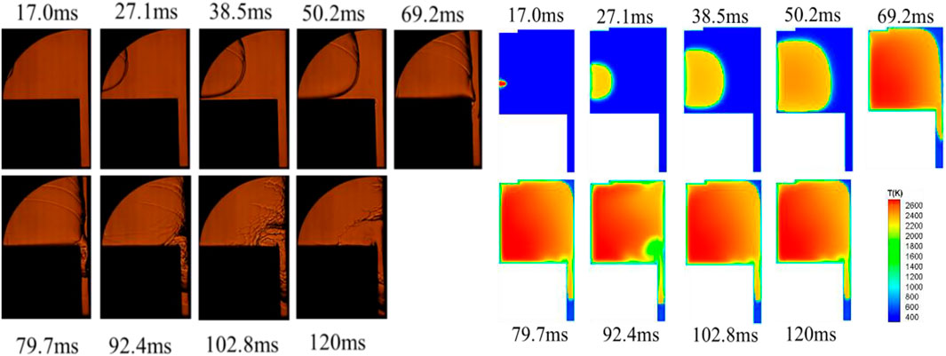
FIGURE 6. Experimental observation and numerical simulation of methane-air flame propagation in the constant-volume combustion chamber under dry wall condition at initial pressure of 0.2 MPa.
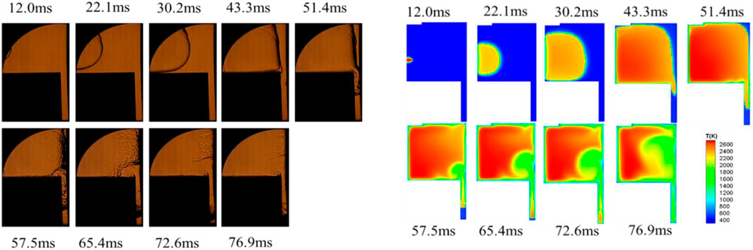
FIGURE 7. Experimental observation and numerical simulation of methane flame propagation under wet wall condition at an initial pressure of 0.2 MPa.
Both the experimental and numerical results in Figure 6 indicated that the propagation of the premixed methane-air flame in the confined combustion chamber cavity and narrow passages could be divided into four stages.
The first stage (0–22.1 m): the methane-air mixture was ignited by the spark plug and accelerated to the right.
The second stage (22.1–30.2 m): the flame propagated spherically with a constant flame speed and the time interval depended on the distance of the ignition position from the side wall.
The third stage (30.2–43.3 m): with the increase of flame area, the flame touched the lower wall surface of the constant volume bomb. The boundary viscous effect of the wall led to the appearance of heat loss, thus slowing down the propagation of the flame compared to the previous stage. Methane-air premixed flame gradually approached to the right wall surface. In addition, under the inhibition of wall conditions, the evaporation of fuel film led to the increase of mixture concentration in the near-wall area.
The fourth stage (43.3–76.9 m): part of the premixed flame entered the narrow channel on the right side, forming the flame edge. The thickness of the flame front surface gradually thickened, and the flame propagation speed in the main combustion chamber decreased significantly. methane-air premixed flame spread stably during its initial access to a narrow channel, then part of the flame bounced back towards the main combustion chamber, causing the flame structure to break up.
Furthermore, the flame surface area in the main combustion chamber was drastically reduced and the flame propagation speed was reduced. In addition, the flame in the narrow passage not only propagated vertically downward in the direction of the passage, but also part of the methane flame in the narrow passage bounced back toward the main combustion chamber at the 60 m moment of flame propagation, causing the phenomenon of airflow coiling suction. The upward coiling airflow could cause part of the reflected flame to enter the main combustion chamber, so that the flame structure in the near-wall area became unstable and broken structures appeared. However, after the bouncing airflow entered the main combustion chamber, it combined with the ignited airflow in the main combustion chamber during the diffusion process, so that the broken flame structure gradually returned to flatness. Apart from that, the flame inside the slit continued to propagate downward, yet the propagation rate slowed down as the thickness of the flame front surface gradually increases. As the heat loss increasing and the methane-air premixed gas in the channel being consumed, the flame propagation speed decreased rapidly and quenching eventually occurred.
Similarly, as shown in Figure 7, the flame propagation process under wet wall conditions also presented four stages. The flame propagation rate was faster when n-dodecane film was present, and the entire combustion process was only about 77 m, comparing to 120 m in the dry wall condition in Figure 6. As the methane-air premixed flame approaching the wall, the flame front surface was pushed away from the right wall surface and the thickness of the flame front surface was increased. The involvement of the liquid film vapor in the combustion reaction sped up the reaction rate and shortened the time in the combustion process. Thus, the presence of the fuel film increased the quenching distance of the premixed flame. The morphological changes and propagation characteristics of the methane-air premixed flame in the restricted slit space conditions also presented four stages, which were presented by high speed schlieren photographs and numerical simulations in the presence of n-dodecane oil film.
A closer look indicated that the flame propagation rate of numerical simulation was slightly faster comparing to the experimental observations. The reason was that the heat generated by the reaction was rapidly dissipated once the combustion reaction of the constant volume bomb was finished during the experiment. In numerical simulations, there might be reactions with residual intermediate substances, and these intermediate products from combustion might store some of the heat that could not be dissipated sufficiently. It made the energy accumulation in the combustion process slightly higher resulting in higher combustion temperature, which accelerated the combustion reaction and consequently led to a faster flame propagation rate during the numerical simulation.
As the methane-air premixed flame propagation and the temperature inside the combustion chamber increase, the n-dodecane fuel film evaporated and participated in the combustion reaction, which consequently affected the distribution of temperature and combustion chemical intermediates in the near-wall region. Figure 8 compared the variations of the average temperature and the distribution of main combustion products in the chamber, under the same initial pressure, of dry and wet wall conditions. In the region away from the wall, the n-dodecane film vapor was not involved in the methane combustion reaction and the temperature in the region was similar to that of the dry wall condition. In the near-wall region, the oil film vapor participated in the exothermic combustion reaction, which promoted the combustion chemical reaction and raised the local temperature. In addition, the amount of methane in the wet wall condition was less because the vapor accelerated the combustion reactions thus increased the consumption of methane in the combustion chamber.

FIGURE 8. Comparison of temperature variation and products distribution in the combustion chamber under dry and wet wall conditions.
Figure 9 compared the exothermic rate of combustion reactions in the cavity with time for dry and wet wall conditions at different initial pressures. In the near-wall region, n-dodecane film vapor participated in the combustion reaction and thus accelerated the heat release, which raised the local temperature by promoting the combustion chemistry and thereby increased the exotherm rate. At the same pressure, the exothermic rate of the entire combustion reaction of wet wall condition was accelerated on the wet wall surface compared to the dry wall surface, and the peak exothermic rate moment was reduced by about 10 m. The peak exothermic rate for the wet wall condition was increased by about 104 J/s compared to the dry wall condition. In addition, the exothermic rate during combustion was affected by the initial pressure. The boiling point of n-dodecane increased with the initial pressure, suppressing the fuel film evaporation. With the latent heat loss of vaporization and energy loss from combustion being reduced, the peak of the exothermic rate increased. However, since the amount of n-dodecane film involved in the combustion reaction was smaller due to the pressure increase, the overall rate of the combustion reaction decreased, hence the time to reach the peak exothermic rate was also delayed.

FIGURE 9. Comparison of exothermic rates of the pre-mixed methane-air mixture between dry and wet wall conditions at different initial pressures.
The effect of different initial pressures on the flame quenching distance was investigated under dry wall and n-dodecane present wet wall condition. Figure 10 showed the variation of flame quenching distance with the initial pressure P0 of 0.2 and 0.4 MPa. The results showed that the initial pressure had a substantial impact on the flame quenching distance, especially when the fuel film was present. The increase in initial pressure led to a decrease in flame quenching distance, from 0.543 mm at 0.2 MPa to 0.397 mm at 0.4 MPa, for the wet wall conditions. This was mainly due to the fact that the boiling point of the hydrocarbons were usually increasing with the pressure, thus the evaporation of the fuel film attached to the wall was inhibited at the same temperature. There was relatively less n-dodecane component at near-wall region under higher pressures, so that the flame could be closer to the wall and the flame quenching distance was reduced. The effect of pressure variation on flame quenching distance was not significant under dry wall condition. It indicated that the flame quenching was controlled by the chemical mechanism of the oil film evaporation, which brought it to the rich combustible limit. The above results and analysis showed that the temperature and initial pressure of the initial premixed gas affected the quenching of the flame by controlling the vaporization of the oil film.

FIGURE 10. Variation of flame quenching distance at different initial pressure.
During the interaction of the flame with the wet wall in the presence of n-dodecane, the presence of the wall film allowed for concentration stratification of the flame during propagation and quenching, resulting in a richer region of mixture. Furthermore, the fuel film might also undergo thermal decomposition at high temperatures, which might result in formation of significant amounts of UHCs (unburned hydrocarbons), soot precursors (C2H2 and C3H3) and aldehydes. Figure 11 showed the distribution of intermediate products within the quenching distance, under dry and wet wall conditions, after quenching of the flame occurring. As it showed, the wet wall condition led to notable increase of all types of combustion products.

FIGURE 11. Distribution of UHC, CO, C2H2 and C3H3 in the quenching aera under dry and wet wall conditions.
Under the wet wall condition, higher temperatures caused faster evaporation of the liquid fuel film from the wall, which led to higher concentrations of carbonaceous substances near-wall. And then, the local equivalence ratio surged to the rich combustible limit, contributing to the increase in flame quenching distance. In addition, the increase in the thickness of the incomplete combustion gas layer resulted in higher UHC and CO. The production of unsaturated hydrocarbons such as C2H2 and C3H3, small molecules associated with carbon soot production, was significantly increased by the influence of the fuel film on the wall. The variation in the concentration of carbonaceous organics in the near-wall area showed that the wall film was expected to produce more soot.
In the present study, the interaction process between the premixed methane-air flame and the n-dodecane film was investigated basing on experimental and numerical methods by a constant volume combustion bomb. The flame propagation process and pressure evolution were analyzed. A two-step method was developed to obtain a kinetic model for the methane and n-dodecane combustion reactions, which was reduced and validated. The effect of the wall film in the constant volume combustion bomb on the methane flame propagation process was investigated by a three-dimensional model numerical calculation. And the heat release rate, wall heat flux and the distribution of combustion materials during the combustion process were analyzed.
The key findings of this study could be summarized as follow: The propagation process of methane-air premixed flame in the constant volume combustion bomb showed four stages in different operating conditions. The flame propagation rate was faster in the presence of n-dodecane fuel film, which was vaporized and participated in the combustion reaction and accelerated the reaction rate and shortened the time during the combustion process, as well as increased the quenching distance of the premixed flame. The presence of slit structures was also found to further increase the instability of the flame structure in the near-wall region. The wall film tended to undergo thermal decomposition resulting in formation of significant amounts of UHCs, soot precursors, aldehydes, etc. thus worsening engine emissions.
The raw data supporting the conclusions of this article will be made available by the authors, without undue reservation.
XL and KW contributed to conception and design of the study. HZ performed the experiment and CL and WC conducted the CFD simulation. SB organized the database and wrote the first draft of the manuscript. HZ and CL wrote sections of the manuscript. XL and KW contributed to manuscript revision. All authors contributed to manuscript revision, read, and approved the submitted version.
This study was supported by the National Natural Science Foundation of China (No. 5217060384 No. 21961122007 and No. 51976135).
The authors declare that the research was conducted in the absence of any commercial or financial relationships that could be construed as a potential conflict of interest.
All claims expressed in this article are solely those of the authors and do not necessarily represent those of their affiliated organizations, or those of the publisher, the editors and the reviewers. Any product that may be evaluated in this article, or claim that may be made by its manufacturer, is not guaranteed or endorsed by the publisher.
The authors also thank the support of the State Key Laboratory of Engines (Tianjin University).
Bai, B., Chen, Z., Zhang, H., and Chen, S. (2013). Flame Propagation in a Tube with wall Quenching of Radicals. Combustion and Flame 160 (12), 2810–2819. doi:10.1016/j.combustflame.2013.07.008
Benajes, J., García-Oliver, J. M., Novella, R., and Kolodziej, C. (2012). Increased Particle Emissions from Early Fuel Injection Timing Diesel Low Temperature Combustion. Fuel 94, 184–190. doi:10.1016/j.fuel.2011.09.014
Bohlin, A., Jainski, C., Patterson, B. D., Dreizler, A., and Kliewer, J. (2016). Multiparameter Spatio-Thermochemical Probing of Flame-wall Interactions Advanced with Coherent Raman Imaging[J]. Proceedings Combustion Inst. 36 (3), 4557–4564. doi:10.1016/j.proci.2016.07.062
Brandriss, M. E., O'Neil, J. R., and Edlund, M. B. (1998). Multi-dimensional Modeling of Thin Liquid Films and spray-wall Interactions Resulting from Impinging Sprays[J]. Int. J. Heat Mass Transfer 41 (20) doi:10.1016/S0017-9310(98)00054-4
Davidson, D., Haylett, D., and Hanson, R. (2008). Development of an Aerosol Shock Tube for Kinetic Studies of Low-Vapor-Pressure Fuels[J]. Combustion and Flame 155 (1-2), 108–117. doi:10.1016/j.combustflame.2008.01.006
Desoutter, G., Cuenot, B., Habchi, C., and Poinsot, T. (2005). Interaction of a Premixed Flame with a Liquid Fuel Film on a wall. Proceedings Combustion Inst. 30 (1), 259–266. doi:10.1016/j.proci.2004.07.043
Dreizler, A., and Böhm, B. (2015). Advanced Laser Diagnostics for an Improved Understanding of Premixed Flame-wall Interactions. Proceedings Combustion Inst. 35 (1), 37–64. doi:10.1016/j.proci.2014.08.014
Foucher, F., Burnel, S., Mounaı̈m-Rousselle, C., Boukhalfa, M., Renou, B., and Trinité, M. (2003). Flame wall Interaction: Effect of Stretch. Exp. Therm. Fluid Sci. 27 (4), 431–437. doi:10.1016/s0894-1777(02)00255-8
Gauthier, G. P., and Bergthorson, J. M. (2016). Effect of External Heat Loss on the Propagation and Quenching of Flames in Small Heat-Recirculating Tubes. Combustion and Flame 173, 27–38. doi:10.1016/j.combustflame.2016.07.030
Huang, H., Zhu, Z., Zhu, J., Lv, D., Pan, Y., Wei, H., et al. (2019). Experimental and Numerical Study of Pre-injection Effects on Diesel-N-Butanol Blends Combustion. Appl. Energ. 249, 377–391. doi:10.1016/j.apenergy.2019.04.163
Ji, C., Dames, E., Wang, Y. L., Wang, H., and Egolfopoulos, F. N. (2010). Propagation and Extinction of Premixed C5-C12 N-Alkane Flames. Combustion and Flame 157 (2), 277–287. doi:10.1016/j.combustflame.2009.06.011
Kang, T., and Kyritsis, D. C. (2005). Methane Flame Propagation in Compositionally Stratified Gases. Combustion Sci. Tech. 177 (11), 2191–2210. doi:10.1080/00102200500240836
Kim, D., Ekoto, I., Colban, W. F., and Miles, P. C. (2008). In-cylinder CO and UHC Imaging in a Light-Duty Diesel Engine during PPCI Low-Temperature Combustion. SAE Int. J. Fuels Lubr. 1 (1), 933–956. doi:10.4271/2008-01-1602
Kim, K. T., Lee, D. H., and Kwon, S. (2006). Effects of thermal and Chemical Surface-Flame Interaction on Flame Quenching[J]. Combustion and Flame 146 (1-2), 19–28. doi:10.1016/j.combustflame.2006.04.012
Klippenstein, S. J., Georgievskii, Y., and Harding, L. B. (2006). Predictive Theory for the Combination Kinetics of Two Alkyl Radicals. Phys. Chem. Chem. Phys. 8 (10), 1133–1147. doi:10.1039/b515914h
Kook, S., Park, S., and Bae, C. (2008). Influence of Early Fuel Injection Timings on Premixing and Combustion in a Diesel Engine. Energy Fuels 22 (1), 331–337. doi:10.1021/ef700521b
Li, Z. S., Li, B., Sun, Z. W., Bai, X. S., and Aldén, M. (2010). Turbulence and Combustion Interaction: High Resolution Local Flame Front Structure Visualization Using Simultaneous Single-Shot PLIF Imaging of CH, OH, and CH2O in a Piloted Premixed Jet Flame. Combustion and Flame 157 (6), 1087–1096. doi:10.1016/j.combustflame.2010.02.017
Lifshitz, A., Scheller, K., Burcat, A., and Skinner, G. B. (1971). Shock-tube Investigation of Ignition in Methane-Oxygen-Argon Mixtures. Combustion and Flame 16 (3), 311–321. doi:10.1016/s0010-2180(71)80102-5
Lipatnikov, A. N. (2017). Stratified Turbulent Flames: Recent Advances in Understanding the Influence of Mixture Inhomogeneities on Premixed Combustion and Modeling Challenges. Prog. Energ. Combustion Sci. 62, 87–132. doi:10.1016/j.pecs.2017.05.001
Liu, H., Ma, S., Zhang, Z., Zheng, Z., and Yao, M. (2015). Study of the Control Strategies on Soot Reduction under Early-Injection Conditions on a Diesel Engine. Fuel 139, 472–481. doi:10.1016/j.fuel.2014.09.011
Liu, W., Koch, J. A., and Law, C. K. (2011). Nonpremixed Ignition of C7-C16 normal Alkanes in Stagnating Liquid Pool. Combustion and Flame 158 (11), 2145–2148. doi:10.1016/j.combustflame.2011.03.013
Najim, Y. M., Mueller, N., and Wichman, I. S. (2015). On Premixed Flame Propagation in a Curved Constant Volume Channel. Combustion and Flame 162 (10), 3980–3990. doi:10.1016/j.combustflame.2015.07.037
Poinsot, T. J., Haworth, D. C, and Bruneaux, G. (1993). Direct Simulation and Modeling of Flame-wall Interaction for Premixed Turbulent Combustion[J]. Combustion and Flame 95 (1-2), 118–132. doi:10.1016/0010-2180(93)90056-9
Qiao, L., Kim, C., and Faeth, M. (2005). Suppression Effects of Diluents on Laminar Premixed Hydrogen/oxygen/nitrogen Flames[J]. Combustion and Flame 143 (1-2), 79–96. doi:10.1016/j.combustflame.2005.05.004
Ritter, E. R., and Bozzelli, J. W. (2010). Therm: Thermodynamic Property Estimation for Gas Phase Radicals and Molecules[J]. Int. J. Chem. Kinetics 23 (9), 767–778. doi:10.1002/kin.550230903
Shen, W., Bai, S., Wang, K., Liao, J., and Liang, X. (2021). Simplified Modeling Combustion Chemistry of Neat and Blended Large Hydrocarbon Fuels with Different Functional Groups. Combustion and Flame 234, 111610. doi:10.1016/j.combustflame.2021.111610
Shi, X., Chen, J.-Y., and Chen, Y. (2017). Laminar Flame Speeds of Stratified Methane, Propane, and N-Heptane Flames. Combustion and Flame 176, 38–47. doi:10.1016/j.combustflame.2016.10.018
Shim, Y.-S., Choi, G.-M., and Kim, D.-J. (2009). Numerical and Experimental Study on Effect of wall Geometry on wall Impingement Process of Hollow-Cone Fuel Spray uUnder Various Ambient Conditions. Int. J. Multiphase Flow 35 (10), 885–895. doi:10.1016/j.ijmultiphaseflow.2009.06.004
Sotton, J., Boust, B., Labuda, S. A., and Bellenoue, M. (2005). Head-on Quenching of Transient Laminar Flame: Heat Flux and Quenching Distance Measurements. Combustion Sci. Tech. 177 (7), 1305–1322. doi:10.1080/00102200590950485
Tang, Q., Liu, H., Li, M., and Yao, M. (2017). Optical Study of spray-wall Impingement Impact on Early-Injection Gasoline Partially Premixed Combustion at Low Engine Load. Appl. Energ. 185, 708–719. doi:10.1016/j.apenergy.2016.10.108
Tao, M., and Ge, H. (2018). Fuel wall Film Effects on Premixed Flame Propagation, Quenching and Emission[J]. Int. J. Engine Res. 21(6), 1055–1066. 10.1177/1468087418799565.
Tao, M., Zhao, P., Vanderwege, B., Iyer, C., and Ge, H. (2020). Further Study on wall Film Effects and Flame Quenching under Engine Thermodynamic Conditions. Combustion and Flame 216, 100–110. doi:10.1016/j.combustflame.2020.02.022
Vishwanathan, G., and Reitz, R. D. (2010). Development of a Practical Soot Modeling Approach and its Application to Low-Temperature Diesel Combustion[J]. Combustion Sci. Tech. 182 (7-9), 1050–1082. doi:10.1080/00102200903548124
Wang, H., You, X., and Ameya, V. J. (2007). High-temperature Combustion Reaction Model of H2/CO/C1-C4 Compounds. Availableat: http://ignis.usc.edu/USC_Mech_II.htm.
Wang, K., Villano, S. M., and Dean, A. M. (2015). Reactivity-structure Based Rate Estimation Rules for Alkyl Radical H-Atom Shift and Alkenyl Radical Cycloaddition Reactions[J]. Am. Chem. Soc. Division Fuel Chem. Preprints 60 (1), 65–67.
Wang, K., Bowman, C. T., and Wang, H. (2019). Kinetic Analysis of Distinct Product Generation in Oxidative Pyrolysis of Four Octane Isomers. Proceedings Combustion Inst. 37 (1), 531–538. doi:10.1016/j.proci.2018.06.219
Yenerdag, B., Minamoto, Y., Aoki, K., Shimura, M., Nada, Y., and Tanahashi, M. (2017). Flame-wall Interactions of Lean Premixed Flames under Elevated, Rising Pressure Conditions. Fuel 189, 8–14. doi:10.1016/j.fuel.2016.10.096
Yu, H., Liang, X., and Shu, G. (2017). Numerical Study of the Early Injection Parameters on wall Wetting Characteristics of an HCCI Diesel Engine Using Early Injection Strategy. Int.J Automot. Technol. 18 (5), 759–768. doi:10.1007/s12239-017-0075-8
Zhang, H., Liang, X., Wang, K., Wang, Y., and Wang, S. (2021). Experimental Study on the Interaction between Flame Propagation and wall Film in a Confined vessel[J]. Fuel. 302, 121132. doi:10.1016/j.fuel.2021.121132
Zhang, J., and Abraham, J. (2016). A Numerical Study of Laminar Flames Propagating in Stratified Mixtures. Combustion and Flame 163, 461–471. doi:10.1016/j.combustflame.2015.10.020
Zhang, Y., Jia, M., Liu, H., and Xie, M. (2016). Development of an Improved Liquid Film Model for spray/wall Interaction under Engine-Relevant Conditions. Int. J. Multiphase Flow 79, 74–87. doi:10.1016/j.ijmultiphaseflow.2015.10.002
Zhao, F., Lai, M.-C., and Harrington, D. L. (1999). Automotive Spark-Ignited Direct-Injection Gasoline Engines. Prog. Energ. Combustion Sci. 25 (5), 437–562. doi:10.1016/s0360-1285(99)00004-0
Zhao, P., Liang, W., Deng, S., and Law, C. K. (2016). Initiation and Propagation of Laminar Premixed Cool Flames. Fuel 166, 477–487. doi:10.1016/j.fuel.2015.11.025
Zhu, D., Egolfopoulos, F. N., and Law, C. K. (1989). Experimental and Numerical Determination of Laminar Flame Speeds of methane/(Ar, N2, CO2)-air Mixtures as Function of Stoichiometry, Pressure, and Flame Temperature[J]. Symp. (International) Combustion. 22(1):1537–1545. doi:10.1016/s0082-0784(89)80164-x
Keywords: flame-wall interaction, two-step reaction scheme, n-dodecane fuel film, methane-air premixed flame, flame quenching distance, engine near-wall emissions
Citation: Bai S, Zhang H, Li C, Wu C, Liang X and Wang K (2022) Experimental and Modeling Study of Wall Film Effect on Combustion Characteristics of Premixed Flame in a Constant Volume Combustion Bomb. Front. Mech. Eng 7:743342. doi: 10.3389/fmech.2021.743342
Received: 18 July 2021; Accepted: 09 December 2021;
Published: 13 January 2022.
Edited by:
Mariano Sirignano, University of Naples Federico II, ItalyReviewed by:
Khanh Duc Cung, Southwest Research Institute (SwRI), United StatesCopyright © 2022 Bai, Zhang, Li, Wu, Liang and Wang. This is an open-access article distributed under the terms of the Creative Commons Attribution License (CC BY). The use, distribution or reproduction in other forums is permitted, provided the original author(s) and the copyright owner(s) are credited and that the original publication in this journal is cited, in accordance with accepted academic practice. No use, distribution or reproduction is permitted which does not comply with these terms.
*Correspondence: Xingyu Liang, bHh5QHRqdS5lZHUuY24=; Kun Wang, a3dhbmc1QHRqdS5lZHUuY24=
Disclaimer: All claims expressed in this article are solely those of the authors and do not necessarily represent those of their affiliated organizations, or those of the publisher, the editors and the reviewers. Any product that may be evaluated in this article or claim that may be made by its manufacturer is not guaranteed or endorsed by the publisher.
Research integrity at Frontiers
Learn more about the work of our research integrity team to safeguard the quality of each article we publish.