
95% of researchers rate our articles as excellent or good
Learn more about the work of our research integrity team to safeguard the quality of each article we publish.
Find out more
ORIGINAL RESEARCH article
Front. Mech. Eng. , 25 March 2021
Sec. Engine and Automotive Engineering
Volume 7 - 2021 | https://doi.org/10.3389/fmech.2021.610891
This article is part of the Research Topic Boosting and Air Handling Technologies for Advanced Power Systems View all 8 articles
While forced induction strategies such as turbocharging can increase the power output and extend the load limit of engines operating on low temperature combustion strategies such as reactivity controlled compression ignition, the low exhaust enthalpy prevalent in these strategies requires the use of high backpressures to attain high turbocharger efficiencies, leading to high pumping losses and in turn poor fuel economy. Hence, there is a need to improve the exhaust energy utilization by the turbocharger such that the negative effects of the high backpressure requirements are offset. One turbocharger operating strategy that has the potential to enhance exhaust enthalpy conversion by the turbine is active control turbocharging (ACT), in which the rack position of a variable geometry turbocharger (VGT) is actuated using a continuously varying sinusoidal signal whose frequency is proportional to engine speed. In this study, the impact of ACT on turbocharger performance and fuel economy of a light-duty reactivity controlled compression ignition engine equipped with a VGT is investigated through coupled GT-POWER/KIVA-3V simulations at a medium-load cruise operating condition. A design of experiments study was executed in which the rack position amplitude and phase angle were independently varied, and the turbine efficiency, compressor efficiency, crankshaft torque, and brake specific fuel consumption were tracked for each run. The results show that ACT operation significantly increased the torque output while improving fuel economy over baseline VGT operation, but the range of actuation signal amplitude ratio was limited to 40% of the maximum amplitude possible due to peak cylinder pressure and peak pressure rise rate constraints. It is also shown that the impact of signal phase angle on turbocharger efficiency and overall system performance is not as significant as the amplitude ratio. The best fuel economy improvement over the baseline VGT operation at cruise conditions was observed at 40% amplitude ratio and 0° phase angle, and this value was 2.8%.
The transportation sector is one of the largest contributors to greenhouse gas emissions, accounting for 29% of total emissions in the United States in 2017 (U.S. EPA, 2019); this number is expected to increase in the future due to the increased demand for travel. To mitigate the impact of these emissions, government regulations for vehicular greenhouse gas limits are becoming more stringent, calling for significant reductions in tailpipe carbon dioxide (CO2) emissions and radical improvements in fuel economy through the use of novel engine technologies. One such technology that has attracted significant attention is low temperature combustion (LTC). Due to lean fuel-air equivalence ratios and the relatively lower temperatures reached at the end of combustion, LTC strategies such as homogeneous charge compression ignition (HCCI) (Najt and Foster, 1983; Thring, 1989), partially premixed combustion (PPC) (Iwabuchi et al., 1999; Okude et al., 2004), and reactivity controlled compression ignition (RCCI) (Hanson et al., 2010; Kokjohn et al., 2011) are able to deliver significant gains in fuel economy and lower oxides of nitrogen (NOx) and soot emissions over conventional diesel and spark ignited (SI) combustion strategies (Caton, 2011).
Despite the aforementioned benefits offered by LTC strategies, major operational challenges such as high unburnt hydrocarbon (UHC) emissions at near-idle load conditions and heat release controllability at high loads hinder the introduction of such strategies in production engines. Controlling the heat release at high loads is especially a problem because it limits the maximum load limit that can be achieved by such engines (Shaver, 2008; Yun et al., 2010). To allow smooth high load LTC operation, it is necessary to use forced induction strategies such as turbocharging and supercharging in combination with exhaust gas recirculation (EGR) so as to increase the working fluid quantity while diluting the fuel-charge mixture for a more controlled heat release at higher loads (Dec and Yang, 2010). Forced induction strategies however come with their own set of drawbacks. Due to the low exhaust gas enthalpy that is prevalent in LTC strategies, it is necessary to use small turbochargers for efficient exhaust energy conversion, which leads to high engine backpressures that in turn contribute to large pumping losses and poor fuel economy (Olsson et al., 2001).
Numerous strategies have been investigated to increase the load limit via forced induction while keeping pumping losses low so as to obtain a fuel economy benefit. Mamalis et al. (2010) compared different compressor configurations from a multicylinder HCCI engine through cycle simulations to determine the ideal boosting setup for HCCI operation. They found that a two-stage turbocharger configuration provided the greatest boost quantity but resulted in the highest pumping work, while a supercharger provided the highest net indicated efficiency due to low pumping work but the lowest brake efficiency due to parasitic losses at the crankshaft. Shingne et al. (2011) compared the two-stage turbocharger configuration to a twincharger (turbocharger–supercharger) configuration for HCCI and discovered that for the same quantity of fresh intake charge inducted for both configurations, the twincharger configuration gave better fuel economy. Wilhelmsson et al. (2007) demonstrated that a variable geometry turbocharger (VGT) helped mitigate pumping losses through a well-defined operating strategy to apply just the right quantity of boost, rather than “overboosting.” Wilhelmsson’s findings were further verified and validated by Taritas and Sjeric (2014) and Mamalis et al. (2012), both showed that the VGT vane position (or rack position) can function as a control knob to obtain sufficient boost while regulating backpressure by appropriately varying the aspect ratio (A/R Ratio) of the turbine.
The aforementioned studies demonstrate that it is more beneficial to use a VGT for LTC applications than other forced induction systems as it allows one to appropriately regulate the turbocharger behavior for more precise control of both the boost pressure and engine backpressure. However, due to the pulsating nature of the exhaust flow from the cylinders, in reality, the flow conditions at the turbine inlet are constantly changing within an engine cycle, and therefore fixing the rack position in a VGT does not allow the turbine to efficiently utilize the exhaust energy throughout the cycle. It is therefore necessary to develop advanced control strategies that can further improve the exhaust energy utilization by the turbine for improved turbocharger efficiency and overall engine fuel economy.
One such advanced control strategy is active control turbocharging (ACT), conceptualized by Rajoo and Martinez-Botas (2007), Rajoo et al. (2014), Pesiridis (2012a), and Pesiridis (2012b) at Imperial College London. In this strategy, the rack position of the VGT is continuously varied by a sinusoidal signal such that the turbine inlet area at any given instant is optimized to the conditions of the exhaust pulses arriving at the turbine inlet. The frequency of the sinusoidal signal is proportional to engine speed, and by appropriately adjusting the amplitude and phase angle of the signal, the turbine inlet area can be optimized continuously, allowing the turbine to more efficiently extract energy from the lower pressure regions of the exhaust pulse. This in turn allows an increase in turbine power and efficiency and an overall increase in engine power. Numerous studies by the aforementioned authors showed that for a heavy-duty diesel engine, ACT was able to increase brake power between 3 and 7% over a traditional VGT (Rajoo et al., 2014). Further follow-up studies by Pesiridis et al. (2011) also showed that a medium duty 8-L diesel engine using an ACT could match or, at some operating points, exceed the power rating of a 10-L heavy-duty diesel engine equipped with a VGT.
Thus far, the potential of ACT has only been examined for conventional diesel engines but has not been evaluated for LTC engine concepts. Hence, the objective of this study is to examine the impact of ACT on the combustion performance and emissions, as well as the turbocharger performance of a light-duty engine running on LTC, specifically RCCI. This study presents simulation results from a one-dimensional gas dynamics model coupled to an in-cylinder computational fluid dynamics (CFD) model on the behavior of a light-duty RCCI engine system equipped with an active control turbocharger. The ACT concept theory is first presented, followed by the model calibration procedure and simulation methodology. Thereafter, the simulation results are analyzed and discussed, and the results obtained from this study are compared with those from previous ACT studies in the literature.
As mentioned in the introduction, active control turbocharging (ACT) involves actively varying the rack position of the VGT vanes using a sinusoidal wave signal. The objective of continuously adjusting the rack position is to ensure that the turbine inlet area at any given point in an engine cycle is optimized to the instantaneous exhaust pulse arriving at the turbine inlet for maximum exhaust energy utilization. The equation of the sinusoidal signal is a modified version of the one used by Pesiridis (2012a) and is as follows:
where kACT,max and kACT,min are the maximum and minimum ACT rack positions, respectively, ω is the angular frequency of the sinusoidal wave, and φ is the phase angle. The angular frequency is in turn defined by the following equation:
where N is the engine speed, G is the number of cylinder groups connected to the turbine inlet, C is the number of cylinders in each cylinder group, and n is the number of strokes per cycle. Note that Pesiridis’ version of the equation has an additional sin (ωt)min term which is derived empirically from the turbocharger flow characteristics observed in gas stand experiments. Since no gas stand data for the NS111 turbine rack position oscillation were available, this term was omitted.
The maximum ACT rack position is taken to be the equivalent VGT rack position at the operating point being studied, while the minimum ACT rack position can be varied to control the peak-to-peak amplitude of the signal depending on the boost pressure and torque requirements. However, there exists a minimum threshold beyond which the minimum rack position cannot be decreased, as the flow into the turbine inlet could become choked, i.e., the Mach number of the flow at the turbine inlet is 1. This threshold is calculated using the pressure-Mach number correlations for isentropic choked flow (Anderson, 2002):
Since the turbine inlet area is directly proportional to rack position, the ratio of rack positions is equal to the choked flow area ratio, and the rack position ratio obtained from the aforementioned correlations can be used to evaluate the minimum allowable rack position
Based on the ACT theory presented in this section, it can be seen that the ACT performance is primarily dependent on two factors: the peak-to-peak amplitude and the phase angle of the actuation signal. It was therefore decided to examine the impact of both these factors on the turbocharger and overall engine system performance using a full factorial design of experiments (DoE) approach. The next section describes in detail the engine specifications, the procedure used to calibrate the simulation models used in this study, and the simulation methodology itself.
Simulations were based on the General Motors (GM) Z19 DTH 1.9 L light-duty turbocharged diesel engine that was converted to run on RCCI. The specifications of the engine and the turbocharger are given in Table 1.
The operating point examined for this study was 8 Bar BMEP at 3,000 rev min−1, which corresponds to a typical highway cruise condition for a light-duty passenger car. Details of the operating point are given in Table 2.
For this simulation study, both one-dimensional gas dynamics and three-dimensional computational fluid dynamics (CFD) models were used to study the impact of active control turbocharging on RCCI combustion performance and emissions. The following subsection describes the features of the models and the procedure of their calibration to experimental data.
A GT-POWER model of the GM 1.9 L engine was used to simulate the gas exchange process, obtain the intake charge properties at IVC for 3D CFD, and study the turbocharger and overall engine performance. The Garrett M53 turbocharger in the GT-POWER model was modeled using supplier generated performance maps for the turbine and compressor. Figure 1 shows the schematic of the GT-POWER Model; note the four port fuel injectors added to the four intake runners (one for each intake runner) to simulate dual fuel RCCI.
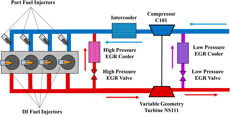
FIGURE 1. GT-POWER model schematic for GM 1.9 L light-duty RCCI engine. The arrows show the direction of air and exhaust gas flows through the respective manifolds.
The in-cylinder combustion between IVC and EVO was modeled in KIVA-3V using a 1/7th sector mesh with periodic boundary conditions as the DI injector had 7 holes. Figure 2 shows the sector mesh used, and Table 3 provides the details of the mesh features.
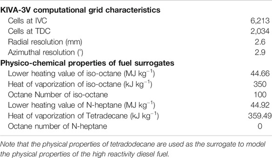
TABLE 3. Computational grid features/characteristics and physico-chemical properties of fuel surrogates used in the KIVA-3V CFD model.
The reduced primary reference fuel (PRF) mechanism developed by Wang et al. (2013) comprising 48 species and 142 reactions was used for combustion chemistry calculations. Iso-octane was used as the surrogate to model the chemical and physical properties of gasoline, while n-heptane was used as the surrogate for the diesel chemistry and tetradecane was used to model the diesel spray break up, collision, and evaporation. To reduce computation time, the SpeedCHEM algorithm and the cell clustering technique developed by Perini et al. (2012) and Perini (2013) were incorporated into the CFD model. Figure 3 shows the flowchart outlining the steps involved in the model calibration procedure.
As the flowchart shows, the fuel quantity, boost pressure, and heat release rate from experiment at 8 Bar BMEP were fed into the multicylinder GT-POWER model to obtain the in-cylinder properties of pressure, temperature, and species mole fractions at intake valve closure (IVC) as well as the crank angle resolved intake and exhaust manifold pressure profiles. The in-cylinder properties were then fed into KIVA-3V to perform the chemistry calculations and calculate the pressure trace. This pressure trace was fed into a single-cylinder GT-POWER model of the 1.9 L engine along with the intake and exhaust manifold pressure profiles at 8 Bar BMEP to perform three pressure analysis (TPA). In the TPA step, the (Woschni (1967)) heat transfer multiplier was adjusted to match the heat loss from KIVA-3V such that the resulting burn rate profile could reproduce the KIVA-3V pressure trace in GT-POWER. This heat transfer tuning approach is similar to the tuning methodology used by Splitter et al. (2013)
The calculated burn rate profile and heat transfer multiplier value were then fed into the multicylinder GT-POWER model to obtain values of brake torque, intake air flow rate, and turbocharger speed. The generated pressure trace, heat release rate profile, and engine performance parameters were then compared with the profiles and values obtained from experiment.
As shown in Figure 4, the in-cylinder pressure was predicted by simulation with acceptable accuracy. The peak heat release rate is however slightly underpredicted compared with experiments despite state-of-the-art models being used, indicating that there are some modeling uncertainties in heat release prediction. However, the discrepancies do not affect the conclusions of the study, and the rest of the heat release rate curve (especially the ramp up and ramp down portions) is predicted with acceptable accuracy. Moreover, from Table 4, it can be seen that the engine system performance parameters such as brake torque and turbocharger speed were predicted with good accuracy. Therefore, the GT-POWER and KIVA-3V models can be taken to be calibrated at the 8 Bar BMEP operating point.
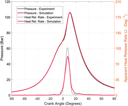
FIGURE 4. Pressure and heat release rate curve comparison between simulation and experiment at cruise condition.

TABLE 4. Comparison of engine performance parameters between test cell and simulation for the 8 Bar BMEP at 3,000 rev min−1 cruise condition.
To simulate the active control turbocharging (ACT) strategy in GT-POWER, the default VGT rack position controller was removed from the baseline multicylinder model and replaced with a control circuit shown in Figure 5. The structure of this circuit is similar to that found in Pesiridis et al. (2011). The control circuit consists of an equation block, which takes the inputs of engine speed, the maximum and minimum rack positions, phase angle, and time and feeds them into the ACT sinusoidal signal equation introduced in the ACT theory section.
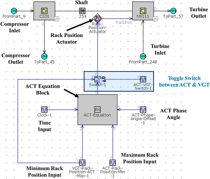
FIGURE 5. ACT control circuit in the GT-POWER model. Note that the VGT rack controller template has been removed and replaced with an ACT equation block template which requires the simulation clock, minimum rack position, maximum rack position, and phase angle as inputs. A toggle switch is also included in this circuit to switch between VGT and ACT if needed. Structure of this circuit is similar to the Ricardo WAVE setup found in Pesiridis et al. (2011).
As indicated in the ACT theory section, the engine speed has to be converted into a corresponding actuation signal frequency to be fed into the equation block using the angular frequency correlation. For the 4-stroke inline 4-cylinder GM 1.9 L engine, there is only 1 cylinder group G, with 4 cylinders in the group. Operating at 3,000 rev min−1, this gives a signal frequency of 100 Hz and an angular frequency of 200 π rad s−1.
For the cruise operating point investigated in this study, the maximum rack position was the equivalent rack position for VGT operation, which is 0.5654. The minimum possible rack position was calculated by feeding in the turbine inlet static and stagnation pressure values for VGT operation into the pressure-Mach number correlation equations presented in the ACT theory section. Table 5 lists the maximum and minimum possible rack positions, as well as the static and stagnation pressures at the turbine inlet for the cruise operating condition.
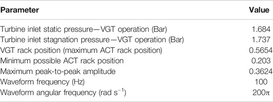
TABLE 5. Calculated values of ACT parameters for the 8 Bar BMEP at 3,000 rev min−1 cruise condition.
As mentioned earlier, for this study, a full factorial design of experiments (DoE) comprising the two factors of sinusoidal signal peak-to-peak amplitude and signal phase angle was performed, with 5 levels for each factor, giving a total of 25 runs. The amplitude was varied from 20% of the maximum amplitude to 100% of the maximum amplitude, in intervals of 20%, while the phase angle was set to values of 0°, 30°, 60°, 90°, and 240° for each amplitude ratio. The phase angle values chosen for this study are the same as those used in the previous studies of Rajoo et al. and Pesiridis et al. The reason as to why specifically the phase angle values of 0°, 30°, 60°, 90°, and 240° were chosen in the original studies (and by extension, in this study) has to do with appropriately timing the rack position amplitude peak and hence the maximum turbine inlet area to the arrival of different “segments” of the exhaust pulse at the turbine inlet. The 30° and 60° phase angles time the peak turbine inlet area to the arrival of the early part of the blowdown segment and the peak pressure segment, respectively, while the 90° and 240° phase angles time the peak inlet area to the arrival of the exhaust pulse somewhere toward the end of the blowdown segment and during the cylinder evacuation segment, respectively. The phase angle selection would depend on which segment of the exhaust pulse one would like to maximize the exhaust energy extraction.
The following constraints/limits were imposed for this DoE study:
1. Peak cylinder pressure limit of 180 Bar.
2. Maximum allowable peak pressure rise rate of 14 Bar deg−1.
3. Constant air-fuel ratio.
4. 0% EGR.
EGR fraction and air-fuel ratio were kept the same as for the baseline VGT condition since the objective of this study is not to optimize the combustion recipe for ACT but to investigate the sensitivity of the amplitude ratio and phase angle on the combustion process as well as overall system performance and to understand ACT’s potential over a traditional VGT operation.
The flowchart in Figure 6 depicts the DoE methodology. For each run, the amplitude ratio and phase angle corresponding to that run were fed into the multicylinder GT-POWER model to calculate the IVC pressure and temperature and the mole fractions of the gas components in the intake charge. To keep the air-fuel ratio constant, GT-Suite’s direct optimizer was used to evaluate the new fueling quantity for each combination of amplitude ratio and phase angle. The calculated values of IVC pressure, IVC temperature, intake charge component mole fractions, and diesel fuel quantity were then fed into KIVA-3V to calculate the pressure trace for each combination of amplitude ratio and phase angle. The KIVA-3V pressure trace, along with the crank angle resolved intake manifold and exhaust manifold pressure profiles corresponding to each run, was fed into the single-cylinder GT-POWER model to perform TPA to generate the burn rate profile for that run, which was then fed into the multicylinder GT-POWER model to evaluate the engine and turbocharger performance parameters.
In the next section, detailed results of the DoE study will be presented and discussed.
The Results and Discussion section is further divided into multiple subsections. In the first subsection (“In-Cylinder Combustion Performance Results”), the in-cylinder combustion performance results are presented and discussed, following which the turbocharger and overall engine performance results are covered in “Turbocharger and Overall Engine Performance Results” section. Section “Emissions Results” covers the impact of the ACT strategy on NOx and soot emissions, and finally, section “Comparison of Results Obtained for ACT Applied to RCCI with Results from Currently Available Research Literature on the ACT Concept” discusses the implications of the observed results as compared with ACT research work available in the current literature.
Figure 7 shows the pressure and heat release rate curves for the baseline VGT case and some of the cases, namely, the 40 and 60% amplitude ratio with 0° and 90° phase angle for each amplitude ratio. As the plots show, with increasing amplitude, the higher in-cylinder trapped mass at IVC results in a higher pressure at the end of the compression stroke, resulting in more favorable kinetics for higher peak cylinder pressures (PCP) and an earlier and more rapid heat release. For example, going from 40% amplitude ratio with phase angle at 0° to 60% amplitude ratio at the same phase angle causes the in-cylinder trapped mass to increase by 6.96%, which causes the PCP to increase by 10.8% from 149.3 to 165.4 Bar.
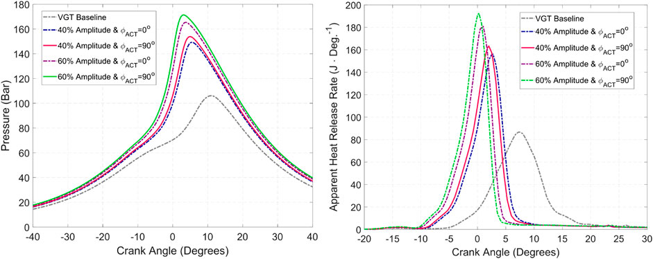
FIGURE 7. Impact of ACT amplitude and phase angle on (left): in-cylinder pressure and (right): heat release rate. Amplitude appears to have a bigger impact on pressure and heat release rate than phase angle.
Within the same amplitude ratio, the increase in trapped mass due to the change in phase angle is not as drastic as the increase in trapped mass as the amplitude ratio is changed. At 40% amplitude ratio, changing the phase angle from 0° to 90° gives an increase of 1.94% in the trapped mass, which in turn gives rise to a PCP increase of 3.8% from 149.3 to 155 Bar.
Figure 8 shows the PCP and peak pressure rise rate variation with amplitude ratio and phase angle for the different runs. Within each amplitude ratio, increasing the phase angle from 0° to 90° causes the PCP to increase due to increased air flow into the cylinders but drops from 90° to 240° due to decreased air flow. Peak pressure rise rate also increases with increasing phase angle from 0° to 90° but decreases as the phase angle is further increased to 240°. Notice however, that adjusting the amplitude ratio results in a more significant change in the PCP and peak pressure rise rate than adjusting the phase angle. Also, at higher amplitude ratios, the effect of increasing phase angle on PCP and peak pressure rise rate becomes more pronounced but still not as pronounced as the effect of increasing amplitude.
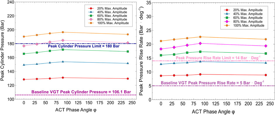
FIGURE 8. Impact of amplitude ratio and phase angle on (left): peak cylinder pressure and (right): peak pressure rise rate.
Figure 9 shows the variation of the crank angle at 50% fuel burnt, CA50 with respect to amplitude ratio and phase angle. It can be seen that as the amplitude ratio increases, the CA50 tends to get more advanced. Beyond 60% amplitude ratio, the CA50 value is pushed back to before TDC for all phase angles.
As discussed earlier, the more favorable kinetics resulting from higher pressures at IVC give rise to the higher PCP values observed with increasing amplitude ratio. The favorable kinetics at higher amplitude ratios are also responsible for an earlier and more rapid heat release that results in more advanced CA50 timings and higher peak pressure rise rates at those ratios. The PCP limit of 180 Bar is exceeded at 80% amplitude for phase angles of 60° and 90° and for all phase angles at 100% amplitude ratio, while the peak pressure rise rate limit of 14 Bar Deg−1 is exceeded beyond 40% amplitude ratio for all phase angles.
Figure 10 shows the impact of amplitude ratio and phase angle on turbocharger shaft speed and turbine isentropic efficiency. Due to the higher fueling and higher trapped mass while keeping air-fuel ratio constant during ACT operation, the exhaust gas flow rates through the turbine are higher for ACT operation over VGT operation. This in turn results in higher levels of absolute exhaust enthalpy arriving at the turbine inlet, giving higher shaft speeds. Similar to the trends observed in the combustion performance parameters, shaft speeds show a slight increase with increasing phase angle up to 90° at each amplitude ratio due to slight increase in the exhaust flow rates up to this point. In addition, the higher exhaust flow rates contribute to increased pressures at the turbine inlet, thereby contributing to a higher expansion ratio across the turbine and therefore increased isentropic efficiency. Beyond a 60% amplitude ratio however, the turbine efficiency begins to drop as the enthalpy utilization by the turbine becomes less efficient despite the overall flow rate and power extracted by the turbine continuing to increase. The minimum rack position at higher amplitude ratios causes the turbine inlet area to become too restricted, thereby causing the backpressure to increase such that the pumping penalty is greater than the turbine efficiency improvement due to higher pressure ratios.
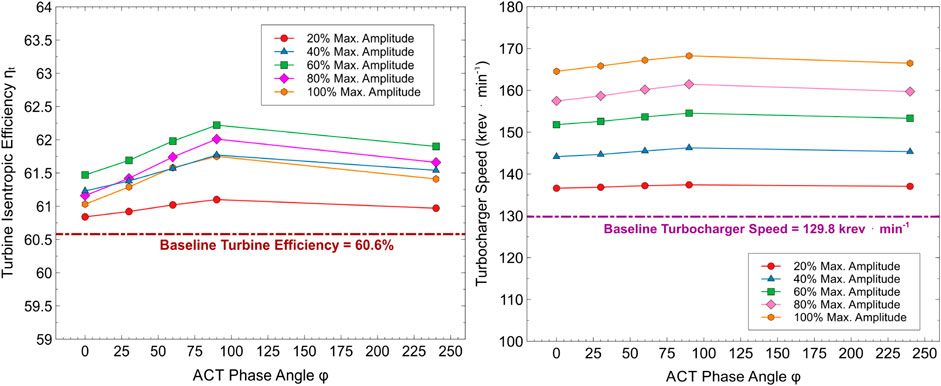
FIGURE 10. Impact of amplitude ratio and phase angle on (left): turbine isentropic efficiency ηt and (right): turbocharger shaft speed.
While the impact of changing the phase angle on the turbine efficiency is not as significant as the impact of changing the amplitude ratio, the effect of changing phase angle becomes more pronounced within the higher amplitude ratios. This shows that adjusting the timing where the maximum turbine inlet area is achieved in an engine cycle affects the quantity of exhaust energy that can be recovered. Clearly, as the phase angle increases up to 90°, a greater portion of the blowdown segment becomes available at the turbine inlet as the maximum inlet area is reached. At 240°, since the high energy blowdown segment has ended and we are well into the evacuation segment, not much exhaust energy is available and so the efficiency drops.
Compared with VGT operation, the compressor efficiency in ACT operation, as well as the intake fresh air flow rate, is higher for all amplitude ratios, as shown by the scatter plots in Figure 11 and the C101 compressor map in Figure 12. As the power generated at the turbine increases with increasing amplitude ratio and phase angle up to
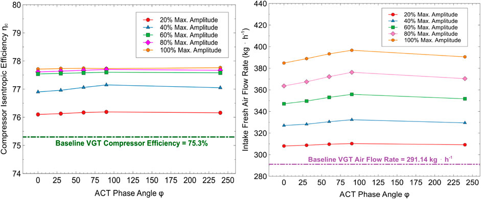
FIGURE 11. Impact of amplitude ratio and phase angle on (left): compressor isentropic efficiency ηc and (right): intake fresh air flow rate.
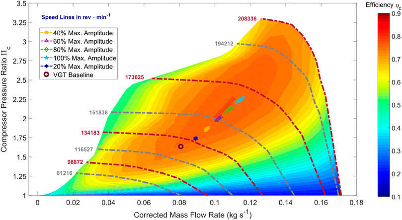
FIGURE 12. C101 compressor map showing the operating points for baseline VGT operation and ACT operation. Note that with ACT, the compressor efficiencies are higher, and the operating points move closer to the heart of the map.
A substantial increase in compressor efficiency is observed with an increase in amplitude ratio up to 60%, and the operating point shifts closer to the heart of the compressor map, as shown by the compressor map contour plot in Figure 12. Further increasing the amplitude ratio beyond 60% gives a negligible rise in efficiency as the compressor is already close to its peak efficiency of 78%. Thus, despite the increased exhaust enthalpy extracted by the turbine, there is a limit as to how much more efficiently the compressor can utilize this enthalpy beyond the 60% amplitude ratio, resulting in a plateauing of the compressor efficiency as shown in Figure 11. As the mass flow rate increases while the efficiency has peaked with increasing amplitude ratio beyond 60%, the operating condition appears to start gradually moving toward the choke region of the map.
Figure 13 shows the impact of amplitude ratio and phase angle on brake torque and brake specific fuel consumption (BSFC). Torque is higher for ACT operation due to higher fueling and greater air flow into the engine, which results in a greater working fluid quantity that in turn gives higher pressures and hence an increase in the torque output at the crankshaft. The impact of amplitude ratio on torque is more significant than the impact of phase angle since the air flow and fueling increase resulting from increased amplitude ratios is much greater than the increase resulting from phase angle changes. At each amplitude ratio, the torque generated is greatest at a 90-degree phase angle.
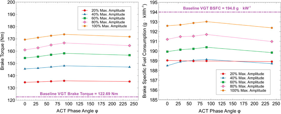
FIGURE 13. Impact of amplitude ratio and phase angle on (left): brake torque and (right): brake specific fuel consumption at cruise conditions.
With regards to BSFC, the overall fuel economy is better with ACT at all amplitude ratios and phase angles than with VGT. This indicates that the exhaust enthalpy extraction by the turbocharger is improved with actively varying the rack position sinusoidally over traditional VGT rack position variation. An assumption made when calculating the BSFC is that the work input needed to oscillate the rack position sinusoidally is negligible in comparison to the total fuel energy.
The BSFC trendlines for the 20 and 40% amplitude ratios appear to fall on top of each other. Although a significant increase in torque is observed as the amplitude ratio is increased from 20 to 40%, the BSFC change is not significant because the required change in fueling per unit energy is not as significant between these two amplitude ratios as it is when the amplitude ratio is increased beyond 40%. This is possibly due to the increase in pumping penalty balancing out the increase in gross indicated efficiency as the amplitude ratio is increased to 40% from 20%. Beyond 40%, the increase in pumping penalty due to the higher backpressures is greater than the increase in gross indicated efficiency with a further increase in amplitude, causing the BSFC to increase.
Within each amplitude ratio from 40% onwards, BSFC slightly increases with increasing phase angle up to 90° and then drops again. This is perhaps due to slight increase in pumping losses within each amplitude ratio as the overall engine backpressure increases and therefore more work is required for the gas exchange process. The lowest BSFC of 188.5 g kW h−1 is observed at the amplitude ratio of 40% and a phase angle of 0°. This value is 2.8% lower than the baseline BSFC of 194.0 g kW h−1 observed during VGT operation. It is also important to note that the peak cylinder pressure and peak pressure rise rate at this lowest BSFC point are 149.3 Bar and 12.8 Bar deg−1, thereby falling within the engine mechanical limits.
Figure 14 shows the brake specific NOx, soot, unburnt hydrocarbon (UHC), and carbon monoxide (CO) emissions for the various amplitude ratios and phase angles. A drastic increase in NOx emissions is observed with an increase in amplitude ratio, which is to be expected due to the challenge in controlling combustion at higher amplitude ratios that leads to rapid rise in pressure and temperature. Thus, it may be necessary to use pressure rise mitigation strategies to control emission formation such as further fuel reactivity stratification, EGR, and Miller cycle using variable valvetrains to maximize the benefit of actively controlling the turbine rack position. Investigation of these strategies is however out of the scope of this study and will be the subject of a future investigative study as the objective of this study is to evaluate the ACT technology for RCCI and identify its strengths and shortcomings in preparation for further optimization studies.
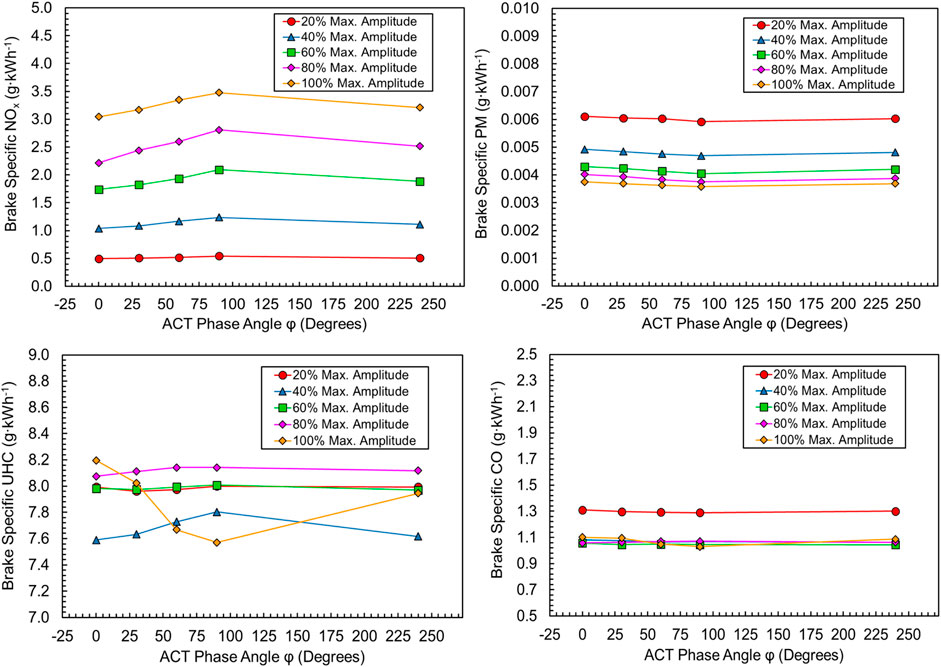
FIGURE 14. Impact of amplitude ratio and phase angle on (top, left): NOx emissions, (top, right): soot emissions, (bottom, left): unburnt hydrocarbon emissions, and (bottom, right): carbon monoxide emissions.
Soot emissions are already low to begin with as expected from LTC strategies such as RCCI primarily due to the highly lean charge-fuel mixtures. As amplitude ratio continues to increase, the soot emissions show a further decrease.
There does not appear to be a clear trend with amplitude ratio and phase angle for the UHC and CO emissions. The UHC values for all cases seem to be between 7.5 and 8.2 g kW h−1. UHC values appear to show an initial drop as the amplitude ratio is increased from 20 to 40% and then increases back to levels similar to those for the 20% amplitude ratio when amplitude ratio is increased to 60%. Then, the UHC values increase as the amplitude ratio increases to 80%, and as the max. amplitude is reached, the UHC values seem to drastically vary with phase angle. CO values hover around 1.1 g kW h−1 for all amplitude ratios, except at 20% amplitude ratio, where the values are around 1.3 g kW h−1. The lack of a clear trend here could be due to the fact that combustion efficiencies are around 97% for all operating points.
To evaluate the impact of ACT on RCCI engine performance, it is of interest to compare the results obtained from this study to those obtained from other ACT studies in the literature. Since no study thus far has investigated the application of ACT to LTC strategies, the phenomena observed in this study were compared with results from ACT applied to conventional diesel combustion, as well as turbocharger gas stand results available in the literature.
Similar to the observations from the studies of Rajoo et al. (2014) and Pesiridis et al. (2011), actively controlling the VGT rack position with a sinusoidal signal increased the quantity of air inducted into the cylinders and also helped improve overall turbocharger energy recovery. This indicates that like in the aforementioned studies, ACT operation improved the turbine exhaust energy utilization by appropriately changing the turbine inlet area to the timing of the exhaust gas pulses arriving at the turbine inlet. Inducting a greater quantity of air into the cylinders while keeping the air-fuel ratio constant also helped increase the crankshaft torque output due to the greater working fluid quantity.
However, the trends observed in engine fuel economy are different for this current study compared with the previous studies of Rajoo et al. (2014) and Pesiridis et al. (2011) The aforementioned studies discovered that using an ACT showed negligible improvement in fuel economy over the baseline VGT at the lower load points, while at higher loads, the fuel economy deteriorated with ACT. The results presented in this study on the other hand show that ACT overall shows an improvement in fuel economy over the baseline VGT case at this medium-load cruise point. One possible reason for the discrepancy is that the turbine wheel and volute configurations used in the studies of Rajoo et al. (2014) and Pesiridis et al. (2011) are different from the turbine wheel and volute configurations of the NS111 turbine on the M53 turbocharger. The turbines used in the studies of Rajoo et al. (2014) and Pesiridis et al. (2011) use mixed flow rotors while the NS111 turbine uses a radial flow rotor. The mixed flow rotors in the turbines used by Rajoo and Pesiridis cause the exhaust gas to impact the rotor blades in an angled, nonradial fashion, while the exhaust flow impacts the blades of the NS111 rotor in a radial fashion. The different flow incidence angles at the rotor blades would be responsible for different flow behaviors between the turbines, which in turn would elicit differences in the exhaust energy utilization between them (Sun, 2011; Sun et al., 2011; Lüddecke et al., 2012). This could potentially result in variations in the turbine and compressor efficiencies, leading to different overall effects on fuel consumption.
In addition to the rotor design, the tip clearance between the rotor and the volute for the two turbines would most likely also be different since the turbine used in the earlier ACT studies is from a turbocharger designed for a heavy-duty truck diesel engine, which will have different design requirements from the NS111 turbine designed for a light-duty passenger car application. The turbine efficiency is also highly dependent on the flow behavior within the volute and around the rotor, which in turn is determined by the tip clearance in addition to the rotor geometry mentioned earlier. The different tip clearances could also potentially be a major reason for the turbine efficiency (Keshavarz et al., 2003) and overall system efficiency discrepancies leading to the differing trends seen in fuel economy changes between VGT and ACT.
In terms of power recovery by the turbine, the results from this current study showed that the power recovery and turbine efficiency increased with an increase in peak-to-peak amplitude of the signal, similar to what Pesiridis and Martinez-Botas (2007) and Pesiridis et al. (2011) observed. However, unlike in Pesiridis’ studies, the impact of phase angle on the power recovered and efficiency in the current study was not as significant as it was in the aforementioned studies. Pesiridis and Martinez-Botas (2007), for example, discovered that changing the phase angle from 90° to 240° at 60 Hz pulsation (corresponding to an operating speed of 2,400 rev min−1 for a 6-cylinder 4-stroke engine with two cylinder groups) caused the power extracted by the turbine to increase by 4.28% and the isentropic efficiency to actually drop. In this study, the isentropic efficiency increased with increasing phase angle up to 90° and dropped at 240°, and the difference in efficiency between the 90° phase angle and 240° phase angle at 60% amplitude ratio is 0.32%. At lower amplitude ratios, the impact of phase angle on efficiency is reduced further. Besides the turbine wheel and volute configuration differences described earlier in this subsection, another possible reason for this discrepancy in the power recovered could be in the rack position mechanism differences between the two turbines. The turbine used in Pesiridis’ studies has a sliding wall mechanism that controls the turbine inlet area, while the NS111 turbine uses a pivoting vane mechanism. Since the sliding wall and pivoting vane mechanisms differ in the way they restrict the inlet area, the optimal phasing of the rack position to the exhaust pulses arriving at the turbine inlet would be different for these different mechanisms. This in turn would lead to differences in performance between the two turbines over the phase angle range, contributing to the discrepancies observed between this study and those of Pesiridis and Martinez-Botas (2007) and Pesiridis et al. (2011). Indeed, Rajoo et al. (2014) found that the efficiency drop decreased while the power extracted increased with a pivoting vane mechanism over the sliding wall mechanism.
Furthermore, the map-based method used in GT-POWER might not have the fidelity necessary to capture the complex unsteady gas dynamics taking place in the turbine volute and rotor passages (Macek and Vitek, 2008; Macek et al., 2009). In the map-based method, gas stand derived steady flow turbine maps at discrete and static VGT rack positions are fed into the engine model, and the software interpolates to find the mass flow rate and expansion ratios at different rack positions when the sinusoidal signal is applied. This approach is quasi-transient at best, and unless the turbine volute and the rotor passages are discretized into one-dimensional flow components in the model, similar to the approach used by Macek and Vitek (2008), Macek et al. (2009), and Macek et al. (2011), the impact of the continuously changing rack position on the unsteady exhaust gas dynamics within the turbine might not be accurately captured. This could be the reason why the impact of phase angle on turbocharger performance might not be as significant using the map-based approach. Representing the turbine with one-dimensional flow components requires extensive validation using gas stand experiments and detailed multidimensional CFD simulations of the turbine, which are out of the scope of this study.
Nevertheless, despite the shortcomings in the turbine representation in the GT-POWER model, the map-based approach still takes into account the impact of the sinusoidally varying rack position and shows a significant sensitivity to the rack position amplitude, so this shows that the model is able to somewhat capture the impact of a sinusoidally varying rack position on the performance of a turbocharger and overall engine performance.
Another major difference between the engine cycle simulations performed by Rajoo et al. (2014) and the simulations executed for this current study would be the mechanical limits considered. Rajoo’s study considered the peak cylinder pressure limit to be the only mechanical constraint, while for the RCCI study, it was also necessary to limit the peak pressure rise rate below 14 Bar deg−1 in addition to the PCP limit of 180 Bar. Due to this additional constraint, it was not possible to exploit the ACT strategy to its full potential by varying the rack position using a 60% amplitude ratio, where the turbine efficiencies were the highest without making significant changes to the combustion recipe. To allow the turbine to operate at its maximum possible efficiency and make further gains in fuel economy using the ACT strategy, it will be necessary to redevelop the combustion recipe at the cruise point such that the CA50 is kept constant and the heat release is more controlled. This can be done by reducing the reactivity of the fuel through an increase in the gasoline to diesel ratio. Heat release could also be controlled by using EGR or VVA strategies such as early or late IVC Miller Cam Timing. However, a more detailed investigation on the impact of these factors while using ACT is needed due to the strong interaction effects between these factors and is therefore out of the scope of this study. A thorough simulation study of combustion recipe optimization for the ACT strategy using Miller cycle, EGR, and fuel reactivity reduction will be the subject of a future study.
In summary, the ACT strategy shows great potential in improving turbocharger efficiency and overall engine fuel economy over traditional VGT operating for a light-duty RCCI engine at a high-speed cruise condition. However, due to the sensitivity of LTC strategies such as RCCI to the intake gas flow conditions and fuel reactivity, the gains in fuel economy due to ACT may have to be limited. Further investigation is needed on detailed turbine behavior and combustion controllability to fully realize the benefits of ACT for RCCI or any other LTC engine system.
In this study, the impact of active control turbocharging (ACT) on turbocharger performance and overall fuel economy for a light-duty RCCI engine at cruise conditions was investigated using one-dimensional gas dynamics simulations in GT-POWER coupled to in-cylinder CFD simulations using KIVA-3V. The goal of this investigation was to determine the benefits and drawbacks of using ACT over the conventional VGT configuration. The following conclusions were drawn from this study:
1. ACT is an effective way to ensure the turbocharger turbine is able to more efficiently utilize the exhaust energy and hence increase engine torque.
2. Change in maximum amplitude ratio has a more significant impact on the combustion and overall system performance and emissions over the change in phase angle at cruise conditions.
3. Rapid rises in peak pressure rise rate are observed with ACT due to higher mass of working fluid (intake charge) inducted into the cylinders. Beyond 40% max. amplitude ratio at medium load/cruise point, peak pressure rise rates become unacceptable. Strategies to optimize the combustion recipe such that the CA50 is kept constant and the heat release rate is more controlled at higher boost pressures are necessary to fully realize the potential of ACT.
4. BSFC improves initially with increasing amplitude ratio up to 40% but drops after that due to increased pumping losses. Increased pumping losses are due to the engine backpressure showing a large increase over the turbine efficiency gain, and the compressor operating closer to peak efficiency of 78% as maximum amplitude ratio is increased.
5. Best improvement in BSFC over baseline is observed at 40% maximum amplitude ratio and zero phase angle, which is 2.8% over the baseline VGT case.
Future work will involve a more detailed investigation into the optimization of the RCCI combustion recipe at the cruise condition by understanding the impact of EGR fraction, fuel reactivity, and variable valve timing on the combustion controllability (i.e., keeping CA50 constant) and determining the ideal value ranges for these aforementioned factors. The consequence of using EGR on the turbine and compressor behavior will also be investigated. In addition, to improve the fidelity of the turbine model in GT-POWER, the turbine volute should be discretized into flow components to capture the one-dimensional gas dynamics effects, and this one-dimensional discretization should be validated with detailed CFD simulations of the NS111 turbine with sinusoidal rack position variation.
The datasets and models used for this study are available upon request. Please contact the corresponding author via e-mail for more information.
AB, RR, and CR contributed to the conception of the simulation study, as well as the simulation procedure. AB executed the simulations and authored the first draft of the manuscript. All authors contributed to the manuscript revision, read, and approved the final submitted version.
This work was supported by the Direct-Injection Engine Research Consortium (DERC), a consortium of 28 automotive companies and the United States government agencies led by the University of Wisconsin Engine Research Center. More information about DERC can be found by visiting the following website: https://derc.wisc.edu/.
The authors declare that the research was conducted in the absence of any commercial or financial relationships that could be construed as a potential conflict of interest.
The authors would like to thank Dr. Reed Hanson and Dr. Scott Curran from Oak Ridge National Laboratory for experimental validation data. They also want to thank Paramjot Singh, Thomas Wanat, and Kevin Roggendorf from Gamma Technologies, Dr. Aaron Costall and Prof. Ricardo Martinez-Botas from Imperial College London, and Prof. Srithar Rajoo from Universiti Teknologi Malaysia for advice and suggestions on active control turbocharger modeling in GT-POWER.
Anderson, J. (2002). Modern compressible flow: with historical perspective. 3rd Edn. Boston: McGraw-Hill.
Caton, J. A. (2011). Thermodynamic advantages of low temperature combustion (LTC) engines using low heat rejection (LHR) concepts. SAE Technical Paper 2011-01-0312.
Dec, J. E., and Yang, Y. (2010). Boosted HCCI for high power without engine knock and with ultra-low NOx emissions - using conventional gasoline. SAE Int. J. Engines 3 (1), 750–767. doi:10.4271/2010-01-1086
Hanson, R. M., Kokjohn, S., Splitter, D., and Reitz, R. (2010). An experimental investigation of fuel reactivity controlled PCCI combustion in a heavy-duty engine. SAE Technical Paper 2010-01-0864.
Iwabuchi, Y., Kawai, K., Shoji, T., and Takeda, Y. (1999). Trial of new concept diesel combustion system—premixed compression-ignited combustion. SAE Technical Paper 1999-01-0185.
Keshavarz, A., Chapman, K. S., Shultz, J., and Kuiper, D. G. (2003). “Effects of turbine blade tip clearance on turbocharger performance: an experimental investigation,” in Proceedings of the ASME 2003 Internal combustion engine and rail transportation divisions fall technical conference. Design and control of diesel and natural gas engines for industrial and rail transportation applications (Erie, Pennsylvania, USA: ASME), 23–31.
Kokjohn, S. L., M., R. , Splitter, D. A., and Reitz, R. D. (2011). Fuel reactivity controlled compression ignition (RCCI): a pathway to controlled high-efficiency clean combustion. Int. J. Engine Res. 12 (3), 209–226. doi:10.1177/1468087411401548
Lüddecke, B., Filsinger, D., and Ehrhard, J. (2012). On mixed flow turbines for automotive turbocharger applications. Int. J. Rotat. Mach. 11, 27. doi:10.1155/2012/589720
Macek, J., and Vítek, O. (2008). Simulation of pulsating flow unsteady operation of a turbocharger radial turbine. SAE Technical Paper 2008-01-0295. doi:10.4271/2008-01-0295
Macek, J., Vítek, O., Burič, J., and Doleček, V. (2009). Comparison of lumped and unsteady 1-D models for simulation of a radial turbine. SAE Int. J. Engines 2 (1), 173–188. doi:10.4271/2009-01-0303
Macek, J., Vitek, O., and Zak, Z. (2011). Calibration and results of a radial turbine 1-D model with distributed parameters. SAE Technical Paper 2011-01-1146. doi:10.4271/2011-01-1146
Mamalis, S., Nair, V., Andruskiewicz, P., Assanis, D. N., Vitek, A., Wermuth, N., et al. (2010). Comparison of different boosting strategies for homogeneous charge compression ignition engines - a modeling study. SAE Int. J. Engines 3 (1), 296–308. doi:10.4271/2010-01-0571
Mamalis, S., Babajimopoulos, A., Guralp, O., and Najt, P. (2012). Optimal use of boosting configurations and valve strategies for high load HCCI-A modeling study. Warrendale, PA: SAE International, SAE Technical Paper 2012-01-1101. doi:10.4271/2012-01-1101
Najt, P. M., and Foster, D. E. (1983). Compression-ignited homogeneous charge combustion. SAE Technical Paper 830264. doi:10.4271/830264
Okude, K., Mori, K., Shiino, S., and Moriya, T. (2004). Premixed compression ignition (PCI) combustion for simultaneous reduction of NOx and soot in diesel engine. SAE Technical Paper 2004-01-1907.
Olsson, J.-O., Tunestål, P., Haraldsson, G., and Johansson, B. (2001). A turbo charged dual fuel HCCI engine. SAE Technical Paper 2001-01-1896.
Perini, F., Galligani, E., and Reitz, R. D. (2012). An analytical Jacobian approach to sparse reaction kinetics for computationally efficient combustion modeling with large reaction mechanisms. Energy Fuels 26, 4804–4822. doi:10.1021/ef300747n
Perini, F. (2013). High-dimensional, unsupervised cell clustering for computationally efficient engine simulations with detailed combustion chemistry. Fuel 106, 344–356. doi:10.1016/j.fuel.2012.11.015
Pesiridis, A., and Martinez-Botas, R. F. (2007). Experimental evaluation of active flow control mixed-flow turbine for automotive turbocharger application. ASME. J. Turbomach. 129 (1), 44–52. doi:10.1115/1.2372778
Pesiridis, A., Dubois, B., and Martinez-Botas, R. F. (2011). A one-dimensional investigation of the effect of an active control turbocharger on internal combustion engine performance. Berlin: Springer. 961–969.
Pesiridis, A. (2012a). Issues in the integration of active control turbochargers with internal combustion engines. Int. J. Automot. Technol. 13 (6), 873–884. doi:10.1007/s12239-012-0088-2
Pesiridis, A. (2012b). The application of active control for turbocharger turbines. Int. J. Engine Res. 13 (4), 385–398. doi:10.1177/1468087411435205
Rajoo, S., and Martinez-Botas, R. F. (2007). Improving energy extraction from pulsating exhaust flow by active operation of a turbocharger turbine. Warrendale, PA: SAE International. SAE Technical Paper 2007-01-1557. doi:10.4271/2007-01-1557
Rajoo, S., Pesiridis, A., and Martinez-Botas, R. (2014). Novel method to improve engine exhaust energy extraction with active control turbocharger. Int. J. Engine Res. 15 (2), 236–249. doi:10.1177/1468087412472414
Shaver, G. (2008). Enabling simultaneous reductions in fuel consumption, NOx, and CO2 via modeling and control of residual-affected low temperature combustion. Emerging environmental technologies. 1st Edn. The Netherlands: Springer, 69.
Shingne, P., Assanis, D., Babajimopoulos, P., Assanis, D., Babajimopoulos, A., Mond, A., and Yilmaz, H. (2011). “Application of a supercharger in a two-stage boosting system for a gasoline HCCI engine: a simulation study,” in ASME 2011 internal combustion engine division fall technical conference, 547–556.
Splitter, D., Wissink, M., DelVescovo, D., and Reitz, R. (2013). RCCI engine operation towards 60% thermal efficiency. SAE Technical Paper 2013-01-0279.
Sun, H., Hanna, D., Hu, L., Zhang, J., Lai, M.-C., Krivitzky, E., et al. (2011). Optimization of a turbocharger for high EGR applications,” presented at the directions in engine efficiency and emissions research conference. Detroit, MI: MacMillan.
Sun, H. (2011). “Advanced boost system development for diesel HCCI/LTC applications,” in Presented at the 2011 Department of Energy Hydrogen Program and Vehicle Technologies Office annual merit review and peer evaluation meeting. United States: Washington District of Columbia.
Taritas, D. K., and Sjeric, M. (2014). Numerical study of boosting configurations and valve strategies for high load HCCI engine in wide range of engine speed. Warrendale, PA: SAE International, SAE Technical Paper 2014-01–1267. doi:10.4271/2014-01-1267
Thring, R. H. (1989). Homogeneous-charge compression-ignition (HCCI) engines. SAE Technical Paper 892068. doi:10.4271/892068
U.S. EPA. (2019). “Inventory of US greenhouse gas emissions and sinks”, EPA430-R-19–001. New York, NY: United States Environmental Protection Agency.
Wang, H., Sjeric, M., and Reitz, R. D. (2013). Development of a reduced primary reference fuel mechanism for internal combustion engine combustion simulations. Energy Fuels 27 (12), 7843–7853. doi:10.1021/ef401992e
Wilhelmsson, C., Tuneståal, P., and Johansson, B. (2007). Operation strategy of a dual fuel HCCI engine with VGT. SAE Technical Paper 2007-01-1855.
Woschni, G. (1967). A universally applicable equation for the instantaneous heat transfer coefficient in the internal combustion engine. SAE Technical Paper 670931.
Keywords: reactivity controlled compression ignition, low temperature combustion, boosting, active control turbocharging, coupled 1D-3D simulation
Citation: Bharath AN, Reitz RD and Rutland CJ (2021) Impact of Active Control Turbocharging on the Fuel Economy and Emissions of a Light-Duty Reactivity Controlled Compression Ignition Engine: A Simulation Study. Front. Mech. Eng 7:610891. doi: 10.3389/fmech.2021.610891
Received: 27 September 2020; Accepted: 27 January 2021;
Published: 25 March 2021.
Edited by:
Ming Jia, Dalian University of Technology, ChinaReviewed by:
Atul Dhar, Indian Institute of Technology Mandi, IndiaCopyright © 2021 Bharath, Reitz and Rutland. This is an open-access article distributed under the terms of the Creative Commons Attribution License (CC BY). The use, distribution or reproduction in other forums is permitted, provided the original author(s) and the copyright owner(s) are credited and that the original publication in this journal is cited, in accordance with accepted academic practice. No use, distribution or reproduction is permitted which does not comply with these terms.
*Correspondence: Anand Nageswaran Bharath, YW5hbmQubmFnZXN3YXJhbi5iaGFyYXRoQGdtYWlsLmNvbQ==
Disclaimer: All claims expressed in this article are solely those of the authors and do not necessarily represent those of their affiliated organizations, or those of the publisher, the editors and the reviewers. Any product that may be evaluated in this article or claim that may be made by its manufacturer is not guaranteed or endorsed by the publisher.
Research integrity at Frontiers

Learn more about the work of our research integrity team to safeguard the quality of each article we publish.