 Yang Zhang1,2,3
 Vigen Arakelian1,2*
- 1LS2N UMR 6004, Nantes, France
- 2Team MECAPROCE, INSA-Rennes, Rennes, France
- 3Department SSE, HEI-YNCREA, Lille, France
This paper deals with the development of single actuator walking robots designed by coupling of two mechanisms. The advantages of such robots are the simplicity of the design and its control system. In this paper, three various design concepts are carried out via coupling of two units which are four-bar linkages, slider-crank mechanisms, and a cam mechanism and a pantograph linkage. The geometrical syntheses of these mechanisms have been analyzed, and based on them, analytical and numerical methods have been adopted to ensure the reproduction of given trajectory similar to the human walking gait. Three single-actuator robots have been designed based on these mechanisms where two of them can be easily reconfigured to reproduce gaits with different lengths or even tilted gaits which make the robot able to climb stairs. All suggested design concepts have been validated through CAD simulations carried out via ADAMS software.
Introduction
Over the past years, many researches have proven that the locomotion on legs is more efficient, faster and more versatile than tracked or wheeled vehicles when it operates over rough terrain, climbs stairs or avoids obstacles. The field of designing legged walking robots which mimics humanoid gait has generated great interest from many researchers and companies.
Pioneering work in the field of legged robots was carried out around 1970 by two renowned researchers, Ichiro Kato (Kato and Tsuik, 1972; Takanishi et al., 1989) and Miomir Vukobratovic (Vukobratovic and Juricic, 1969; Vukobratović, 1975). Both works were characterized by the design of relevant experimental systems. In Japan, the first anthropomorphic robot, WABOT 1, was presented in 1973 at Waseda University. While Miomir Vukobratovic and his team in Yugoslavia designed the first active exoskeletons and several other devices. Over the next decade, breakthroughs came from the United States (Gubina, Hemami and McGhee, 1974; McGhee, 1985; Raibert and Tello, 1986). Simultaneously, Robert McGhee and Kenneth Waldron, carried out the design of a quasi-industrial system capable of walking on uneven natural terrain, which was driven by a human (Waldron and McGhee, 1986; Song and Waldron, 1989). Industrial breakthroughs in the recent twenty years have shown the world that building true humanoids is now possible. The first humanoid robot of Honda, P2, was exhibited in 1996 (Hirai et al., 1998), followed by several others: ASIMO (Honda), QRIO (Sony), Atlas (Boston Dynamics), etc.
Normally, it is necessary to use many actuators to create humanoid walking robots in order to mimic the human leg joint configuration. These robots hence are automorphic and flexible. However, these features lead to some drawbacks: complexities of the design and the control system, low efficiency and high inertia due to the mass of the motors, as well as high costs. However, different methodologies can be considered for building a humanoid robot with reduced number of degrees of freedom (DOF) such as by using leg mechanisms which are an assembly of links and joints intended to create human- or animal-like walking gait (Zhang and Arakelian, 2020). In the early of 20th century, Pafnuty Chebyshev suggested the very first walking machine using a four-bar mechanism that converts rotational motion into rough straight-line motion with constant approximate speed (Plantigrade Machine, 2016). Other types of linkages were also used for the design of the reduced DOF legged robot except for four-bar linkages. A walking robot based on an eight-bar leg mechanism was proposed by Simionescu (Simionescu and Tempea, 1999). Another famous six-link leg mechanism which designed by the American engineer Joseph Klann is the Klann linkage (Klann, 1998). Theo Jansen designed a 12-link planar leg mechanism for his “Strandbeest” kinetic sculptures which intends to move on its own while propelling by the wind (Jansen, 2007). However, one of the biggest drawbacks of these mechanisms is that the produced gait is difficult to modify because the lengths of the links are fixed and hard to be adjusted.
In this paper three legged robots with only one degree of freedom by coupling three different mechanisms are proposed. The kinematics of these mechanisms is presented in Kinematics of Single Degree-of-freedom Mechanisms for analyzing the relationship between the geometrical parameters and output trajectory. Then, the geometrical parameters of these mechanisms are numerically or analytically optimized for generating desired gait and based on them, three legged robots with only a single actuator are proposed in Single-Actuator Walking Robots Design. Finally, the results of numerical simulations of these robots are provided in Numerical Simulation via ADAMS and conclusions of this paper are made in Conclusion.
Kinematics of Single Degree-of-freedom Mechanisms
The relationship between the kinematics and geometrical dimensions of the mechanism is very complicated since the output path of the mechanism depends on the length of all the linkages and sometimes subjected to some nonlinear constraints. Hence for having a mechanism that generates desired path, one must firstly conduct kinematic analysis of the mechanism.
In this section, three single-DOF mechanisms are proposed, and their kinematics are presented respectively in the following.
Four-Bar Mechanism
Four-bar mechanism is one of the simplest but widely used single DOF mechanism. It has been used in various applications such as pumpjack, gear shift linkages, bicycle suspension, wiper-blades mechanism, etc.
Figure 1 shows a planar 4-bar mechanism where the geometrical parameters are r1, r2, r3, r4, rcx, rcy, θ0, x0, y0. And as the input link AD turns with an angle θ2, the following link BE will rotate with an angle θ4 and the coupling point C will generate a certain trajectory while following the movement.
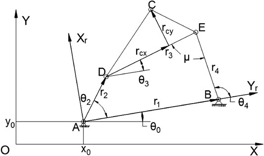
FIGURE 1. A planar four-bar mechanism with design parameters.
In order to calculate the coordinates of the generating path, firstly we have to calculate the value of θ3. The closed equations of the four-bar linkage are:
It can be rewritten as
By taking the sum of squares of the equations in Eq. 2, a quadratic equation with respect to cosθ3 can be obtained. And the solution can be represented as flowing:
where:A = 2r3(r2cosθ2 − r1)B = r24 − r21 − r22 − r23 + 2r1r2cosθ2C = 2r2r3sinθ2D = (A2 + C2)1/2
Then θ3 and θ4 can be easily calculated:
Thus, the coordinate of point C in the local frame O2XrYr, which has been defined in Figure 1, is:
and its position in the reference OXY can be obtain by simply multiplying a rotational matrix:
Adjustable Slider-Crank Mechanism
Apart from 4-bar mechanism, another famous single-DOF mechanism often used in the industrial field is the slider-crank linkage. A slider-crank linkage is a four-link mechanism that consists of three revolute joints and a prismatic joint, the rotational movement of the crank is transferred to the linear movement of the slider.
In this paper, an adjustable slider-crank mechanism is proposed as shown in Figure 2. In the mechanism, the crank OA rotates about the fixed pivot O, and the slider is linked with crank OA via connecting rod AB. Unlike a conventional slider-crank mechanism, the slider moves on an offset slideway and a second rod AC is fixed with link AB for generating the output trajectory at point C. One of the great advantages of this mechanism is that the output trajectory can be changed trough adjusting the offset distance of the slideway and the angle between link AB and rod AC, whereas for the four-bar linkage, the output trajectory can be only changed by altering the links’ length.
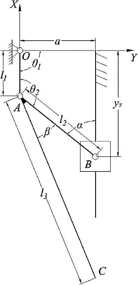
FIGURE 2. The adjustable slider-crank mechanism.
For a given input angle of the mechanism θ1, the coordinates of the point A can be expressed as:
where l1 is the length of the link AB.
Then the position of slider B can be calculated by:
where l2 is the length of connecting rod AB and, a is the distance between the slider guide and the fixed pivot O.
The counterclockwise angle between the links OA and AB is:
where vOA and vAB denote the vector from point O to point A and from point A to point B respectively.
Thus, the coordinates of the coupler point C can be written as:
where l3 is the length of the link AC and β is the angle between link AB and rod AC.
Driven Cam System and Pantograph Mechanism
A cam is often a rotational part whose profile is well design for transforming rotary motion into a prescribed linear motion. It is often used to produce a smooth reciprocating motion in the follower which is in contact with it.
The proposed single-DOF mechanism in this section contains a cam which can change the inclination angle connected with a pantograph mechanism for amplifying the motion of the follower. In this walking mechanism, two adjustable parameters are introduced: the cam inclination angle and the fixed point position of pantograph mechanism.
Figure 3 shows the generated trajectories of the proposed mechanism with different fixed points of pantograph mechanism and different angle of inclination of the cam. As it can be seen from Figures 3A,B, the follower C follows the profile of the cam and generates identical input trajectories to the pantograph mechanism. However, with different fixed point on
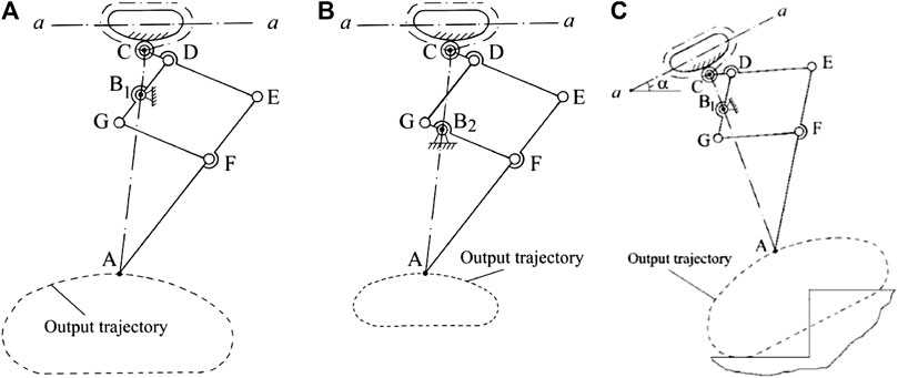
FIGURE 3. Leg mechanism with different output trajectories (A. fixed point on B1, B. fixed point on B2, C. with a cam inclination angle α).
Figure 3C shows the output trajectory of the proposed mechanism after changing the second adjustable parameter which is the rotation angle of the axis a-a of the cam mechanism denoted by
Single-Actuator Walking Robots Design
For designing a walking robot with a single-DOF leg mechanism, it must generate a desired path which is a walking gait with desired step length and height.
In this section, three single-DOF robots are designed based on the mechanisms proposed in the previous section. In order to have the desired path, geometrical syntheses are also conducted by using numerical or analytical methods.
Via Coupling a Four-Bar Mechanism
In early years, many researchers have tried to use graphical and analytical synthesis of the four-bar mechanism for obtaining a desired motion (Hartenberg and Denavit, 1964; Freudenstein, 2010). But due to the complexity and the high nonlinearity of the kinematic of four-bar mechanism, these methods are usually of low precision and will increase computational time when the prescribed points increase (Erdman and Sandor, 1984). However, with the significant development of the computer industry, numerical methods become strong and useful tools for solving sophisticated optimization problems. The genetic algorithm (GA), among these numerical methods, is one of the most efficient approaches to solve global optimization problems (Holland, 1973).
In order to use GA for solving the geometrical synthesis, firstly we have to formulate it as an optimization problem. Normally, an optimization problem consists of three parts: the optimization variables, cost function to minimize, and constraints of variables. Because the goal of geometrical synthesis is to let the mechanism generate a path which is close to the given points, so the cost function can be described as the total difference between the prescribed points and the actual generated path by four-bar mechanism. For having an optimal solution, several constraints must be applied like Grashof condition, sequence condition, as well as the limitation of variable. Hence, the optimization of the four-bar mechanism can be formulated as following.
subject to:
(1) Grashof condition: 2(rmax + rmin) < (r1 + r2 + r3 + r4)
(2) Sequence condition: < θmod(j+1,N)2 < … < θmod(j+N,N)2
(3) Constraints of design variables:
where
The genetic algorithm toolbox in Matlab is used for solving the proposed optimization problem and the settings are showed in Table 1 where the desired points are chosen on a gait with a stride of 40 mm and a step height of 16 mm. The optimization process achieve an optimal solution at 50th generation with a final error of 0.029 and the optimal variables of the four-bar mechanism are: r1 = 34.38 mm; r2 = 12.45 mm; r3 = 33.19 mm; r4 = 40.85 mm; rcx = 14.66 mm; rcy = 34.20 mm; θ0 = 0.249; x0 = 44.95 mm; y0 = 25.73 mm; θ12 = 5.806; θ22 = 6.209; θ32 = 0.221; θ42 = 0.524; θ52 = 0.949; θ62 = 3.481.

TABLE 1. General Setting of the optimization.
The left part of Figure 4 shows the obtained mechanism as well as the input and output trajectory where for the motion or input crank, the thick and thin dot lines stand for generated stand and swing phase of walking gait respectively. Because of the two phases are dived symmetrically with a difference of 180°, the design of the walking robot can be achieved based on the optimal four-bar mechanisms while actuating by only one motor. The CAD model of the proposed walking robot is shown in the right side of Figure 4 where two four-bar mechanism are coupled on the robot and a single motor is install in between. For achieving the balance of the robot, two feet are connected to the four-bar mechanisms via torsion springs.
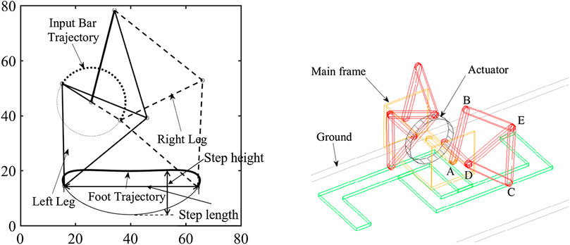
FIGURE 4. Leg trajectory of the optimized four-bar mechanism and schematic representation of the robot with this mechanism.
Via Coupling an Adjustable Slider-Crank Mechanism
For the proposed adjustable slider-crank mechanism in Adjustable Slider-Crank Mechanism, when the lengths of the links are determined, its capability of generating various path is ensured by the adjustment of the offset of slider guide a and the angle β between the links AB and AC. The output path at the point C is constrained by the geometric property of dyad OAC where all the generated paths are tangent to two concentric circles with radii of
Different paths generated by adjusting the value of a and β of the proposed slider-crank mechanism with the non-dimensional lengths of links l1 = 1, l2 = 5, l3 = 10 are show in Figure 5. The various adjustable parameters of the paths are as following: path (a): β = 20 deg, a = 2; path (b): β = 10 deg, a = 2; path (c): β = 20 deg, a = 3; path (d): β = 10 deg; a = 3.
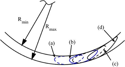
FIGURE 5. Different paths generated by the adjustable slider-crank mechanism.
In order to apply the proposed mechanism for designing the single actuator robot, let us first assume that for a full range of motion of the driving link OA
Thus, to ensure this constraint, only one adjustable parameter a should be considered.
The two input angles of the left and right leg,
Then the step length lstep of the leg mechanism can be obtained by:
In the proposed design of the single-actuator walking robot, the lengths of each link of the leg mechanism are chosen as following: l1 = 20 mm, l2 = 100 mm, and l3 = 400 mm. And the moving range of the slider guide is
The step length with respect to the slider guide position is shown in Figure 6. While the slider guide is moving away from the fixed pivot, the step length of the leg mechanism is increasing exponentially.
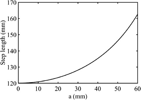
FIGURE 6. Step length with respect to the slider guide position.
For illustration and evaluation of the performance of the proposed design, a CAD model has been built (Figure 7). As shown in the figure, the grey box is the body frame of the robot which contains the actuator, battery, transmission system and payload. Two adjustable slider-crank mechanisms are linked with the body on the left and right sides. In order to keep the feet always being parallel to the ground, parallelogram mechanisms have been created between the leg mechanisms and the feet.
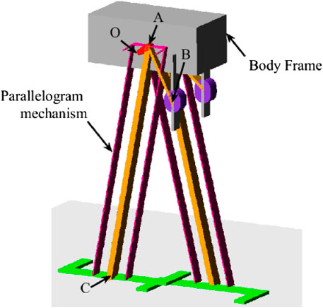
FIGURE 7. ADAMS model of the proposed design.
Via coupling of the driven cam system and pantograph mechanism.
For the driven cam system, the follower tracks the profile of the cam and generates an input trajectory for the pantograph mechanism. Hence, in order to design a walking robot with the third proposed mechanism, the cam profile needs to be similar to a walking gait.
The left of Figure 8 shows the robot’s body which includes a main body, two cams on each side whose profile has a straight line and a curve representing the stand phase and swing phase respectively, two rolling balls were inserted into the profile of each cam, two rolling bars on each side which rotate about the center of each cam. Two sliders link to the rolling balls on one side and link to the input point of pantograph mechanism on the other side and have translational motion with rolling bars.
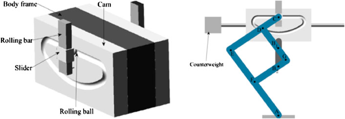
FIGURE 8. Robot’s body and the robot with pantograph mechanism and a counterweight.
The geometrical coordinates of the pantograph mechanism used for the proposed walking robots are shown in Table 2. For proposed mechanism, the amplify ratio is 2 and 1 respectively when the fixed point is on B1 and B2. And in order to keep the balance of the robot, a movable counterweight was also added on the robot. The right of Figure 8 shows the CAD model of the robot after coupling the pantograph mechanisms.
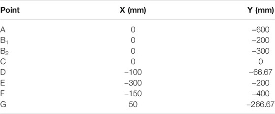
TABLE 2. Coordinates of the axes, input and output points of the pantograph mechanism.
Numerical Simulation via ADAMS
In order to validate the functionality and feasibility of three proposed walking robots, simulations via ADAMS have been conducted with each robot respectively under different speed settings and different adjustable parameters for the reconfigurable ones.
Legged Walking Robot With Four-Bar Mechanisms
In the simulation of the robot with four-bar mechanisms, the speeds of actuator have been set as 60 deg/s, 120 deg/s, -60 deg/s respectively for simulating the performance or the robot in different speeds and different walking directions.
Figure 9 shows the captured snapshots during the simulation while the robot is walking with the actuator speed at 60 deg/s. The simulations also validated that the robot has good performance while it’s walking in the reverse direction.
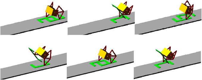
FIGURE 9. Snapshots of the simulation when robot moving forward.
The displacements the robot during simulations with different actuator speeds are shown in the left part of Figure 10. As we can see from these two figures, the robot was able to walk at a relative constant speed for the different input actuator speed. The energy consumption of this robot is shown in the right part of Figure 10. We can see that at 0–10% and 50–60% of the gait phase in which the gait is transiting between swing and stand phase, fluctuation occurred due to the contact between foot and ground.
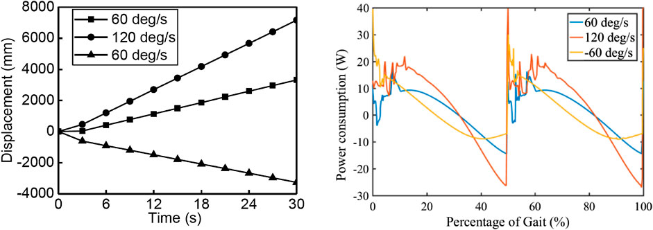
FIGURE 10. Displacements of the robot with different walking speeds and energy consumption of the robot.
Legged Walking Robot With Adjustable Slider-Crank Mechanisms
In the simulations of the robot with adjustable slider-crank mechanisms, four configurations of the adjustable mechanism are chosen and their offset of slider guide (a), fixed angle (β), and step length are shown in Table 3. It can be seen that by changing the adjustable parameters, four gaits with different step length were produced.
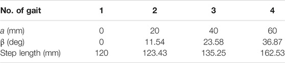
TABLE 3. Variation of adjustable parameters and step length of the leg mechanism.
Simulations of the proposed design with different adjustable parameters have been carried out via ADAMS. All the simulations have been carried out with the input rotational velocity of the input crank as 30 deg/s.
Figure 11 shows the snapshots of the animation of simulations while the robot is walking with two different configurations of the leg mechanism (gait 1 and gait 4). For all the simulations, the robot can walk steadily and the distance between the two snapshots is increased when the offset of the glider is increased.
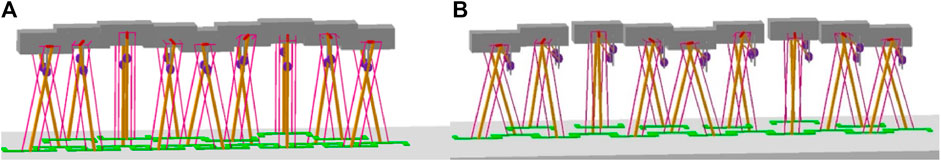
FIGURE 11. Snapshots of simulations with different configuration (A. gait 1, B. gait 4).
The horizontal displacement of the robot and the energy consumption with different configurations are shown in Figure 12. For all the simulations, the robot can walk with a constant speed and the speed changes with the variation of the offset of the slider guide. During the swing phase (0–50% of the gait cycle), the energy consumption is very low since the energy is only used for moving the leg. And during the stand phase (50%–100%), the energy is used for actuating the robot to walk forward and the energy consumption is increased as the robot’s walking speed is incr.
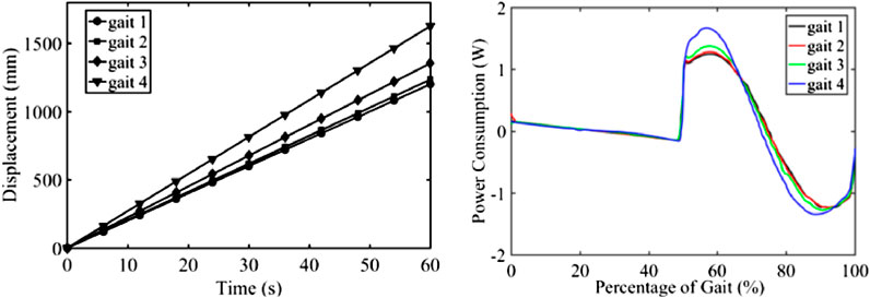
FIGURE 12. Horizontal displacement and energy consumption of the robot.
Legged Walking Robot With Cam and Pantograph Mechanism
Simulations of the robot with cam and pantograph mechanisms are carried out with different environments (plane surface and stairs). The first two simulations were conducted while the robot was walking on a plain terrain and the pantograph mechanism’s fixed point was on B1 and B2 respectively. The same input motion speed was set for both of the simulations. Figure 13 shows the horizontal displacement and and power consumption of the actuator with the fixed points on B1 or B2. And the snapshots of the simulations are shown in Figures 14A,B. It can be seen that, with different fixed positions, the walking robot can generate different gait with different length. The power consumption is also increased when this fixed point is on B1 while the robot is walking with a larger step.
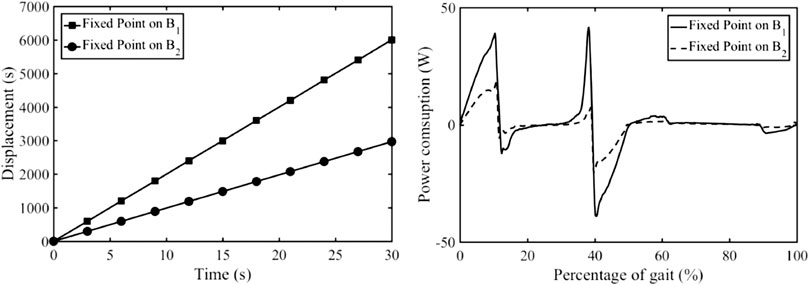
FIGURE 13. Horizontal displacement and power consumption of the actuator with fixed points: B1 and B2.
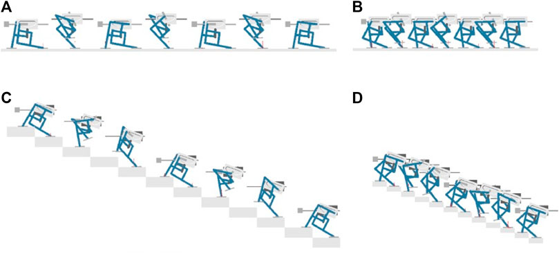
FIGURE 14. Snapshots of simulations with different adjustable parameters (A. fixed point on B1, α=0°, B. fixed point on B2, α=0°, C. fixed point on B1, α=20°, D. fixed point on B2, α=20°).
The second set of two simulations were carried out for evaluating the robot’s performance while climbing stairs. Similar to the previous simulations, the same input motion was executed on each side of the rolling bars, the cam inclination angle of both legged mechanism was set to 20 deg. Figure 15 shows the horizontal and vertical displacements of the walking robot when the fixed point is on B1 or B2. Figures 14C,D show the snapshots the two simulations with different fixed points. It can be seen that, after changing the cam angle
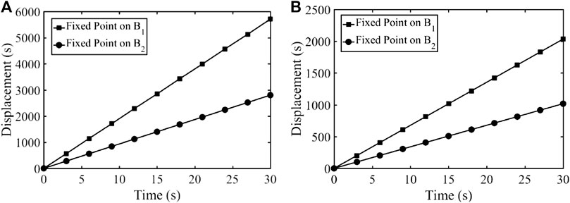
FIGURE 15. Horizontal (A) and vertical displacement (B) when the fixed point on B1 and B2.
Conclusion
In this paper, the various techniques of the design of single actuator walking robots have been considered. These designs were achieved via the coupling of different kinds of mechanisms.
In the first section, three single-DOF mechanisms are proposed including a four-bar mechanism, an adjustable slider-crank mechanism, and a driven cam system with pantograph mechanism. For analyzing the relationship between the geometrical parameters and the generated path, kinematics of these mechanisms is presented.
Based on the previously proposed mechanisms, three legged walking robots with only a single actuator are designed. In order to make these robots generate a suitable gait for walking, geometrical syntheses are conducted by using numerical or analytical methods. For the robot with four-bar mechanism, a numerical optimization method based on GA for solving the geometric synthesis of 4-bar mechanism is proposed. This method allows one to find the optimal configuration of four-bar linkage that can generate a desired trajectory based on given design points. The proposed legged robot consists of only one actuator and two optimized four-bar mechanism are coupled on it. Next, a robot with adjustable slider-crank mechanisms has been designed. It shows that the output trajectory of the suggested design can be changed while changing the offset of the slider guide. The step length of the robot is exponentially increased when the slider guide is moving away from the fixed pivot. Finally, a single-DOF legged robot using cam and pantograph mechanism with two adjustable parameters is proposed. The two adjustable parameters are the angle between the cam mechanism and the robot body and the fixed point position of the pantograph mechanism. Analysis shows that the robot can generate gaits with different step length and tilted gait.
Simulations of the three presented walking robots have been conducted via ADAMS software for validated their capability. Results showed that the robot with four-bar mechanism is able to walk steadily in different walking directions with difference speeds. And for the robot with adjustable slider-crank mechanism, simulations have been done with four different given combinations of adjustable parameters, and results showed that the robot can walk steadily with different step lengths. The obtained results of the last design showed that the robot’s walking gait and its speeds are evidently changed due to the adjustment of pantograph mechanism’s fixed point position. Meanwhile, the variation of the cam inclination angle let the robot be able to climb stairs, while the value of this angle depends on the stair’s slope.
Data Availability Statement
The original contributions presented in the study are included in the article/Supplementary Material, further inquiries can be directed to the corresponding author.
Author Contributions
This study was carried out within the framework of the thesis of YZ supervised by VA.
Conflict of Interest
The authors declare that the research was conducted in the absence of any commercial or financial relationships that could be construed as a potential conflict of interest.
References
Erdman, A. G., and Sandor, G. N. (1984). Advanced Mechanism Design : Analysis and Synthesis, Vol. 2. Upper Saddle River, NJ: Prentice-Hall.
Freudenstein, F. (2010). Approximate synthesis of four-bar linkages. Resonance 15 (8), 740–767. doi:10.1007/s12045-010-0084-7
Gubina, F., Hemami, H., and McGhee, R. B. (1974). On the dynamic stability of biped locomotion. IEEE Trans. Biomed. Eng. 21, 102. doi:10.1109/TBME.1974.324294
Hartenberg, R. S., and Denavit, J. (1964). Kinematic synthesis of linkages. New York, NY: McGraw-Hill.
Hirai, K., Hirose, M., Haikawa, Y., and Takenaka, T. (1998). The development of Honda humanoid robot,in Proceedings. 1998 IEEE International Conference on Robotics and Automation, Leuven, Belgium, August 2, 2002, IEEE, 1321–1326. doi:10.1109/ROBOT.1998.677288
Holland, J. H. (1973). Genetic algorithms and the optimal allocation of trials. SIAM J. Comput. 2 (2), 88–105. doi:10.1137/0202009
Kato, I., and Tsuik, H. (1972). “The hydraulically powered biped walking machine with a high carrying capacity,” in Proceedings of 4th International System on External Control of Human Extremities, Dubrovnik, Croatia, August 28–September 2, 1972.
McGhee, R. B. (1985). “Vehicular legged locomotion”, in Advances in Automation and Robotics, 1. Greenwich, CT: Jai Press, 248–259.
Plantigrade Machine (2016). Available at: http://en.tcheb.ru/1 (Accessed May 25, 2016).
Raibert, M. H., and Tello, E. R. (1986). Legged robots that balance. IEEE Expert. 1, 89. doi:10.1109/MEX.1986.4307016
Simionescu, P.A., and Tempea, I. (1999). “Kinematic and kinetostatic simulation of a leg mechanism,” in Proceedings of the 10th International Conference on the Theory of Machines and Mechanisms. Oulu, Finland, June 20–24, 1999.
Song, S.-M., and Waldron, K. J. (1989). Machines That Walk: The Adaptive Suspension Vehicle. 1943. Cambridge, United States: MIT Press.
Takanishi, A., Tochizawa, M., Takeya, T., Karaki, H., and Kato, I. (1989). Realization of Dynamic Biped Walking Stabilized with Trunk Motion Under Known External Force. in Advanced Robotics. (Berlin, Heidelberg: Springer), 299–310. doi:10.1007/978-3-642-83957-3_21
Vukobratovic, M., and Juricic, D. (1969). Contribution to the synthesis of biped Gait. IEEE Trans. Biomed. Eng. BME-16 (1), 1–6. doi:10.1109/TBME.1969.4502596
Vukobratović, M. (1975). Legged Locomotion Robots and Anthropomorphic Mechanisms: A Monograph. Beograd, Serbia: Mihailo Pupin Institute.
Waldron, K. J., and McGhee, R. B. (1986). The adaptive suspension vehicle. IEEE Contr. Syst. Mag. 6, 7–12. doi:10.1109/MCS.1986.1105145
Keywords: mechanism design, walking robot, leg mechanism, four-bar linkage, slider-crank mechanism, pantograph mechanism
Citation: Zhang Y and Arakelian V (2021) Design and Synthesis of Single-Actuator Walking Robots via Coupling of Linkages. Front. Mech. Eng 6:609340. doi: 10.3389/fmech.2020.609340
Received: 23 September 2020; Accepted: 08 December 2020;
Published: 26 January 2021.
Edited by:
Giovanni Gerardo Muscolo, Polytechnic University of Turin, ItalyReviewed by:
Guiyang Xin, University of Edinburgh, United KingdomDarius Eidukynas, Kaunas University of Technology, Lithuania
Carlotta Mummolo, New Jersey Institute of Technology, United States
Copyright © 2021 Zhang and Arakelian. This is an open-access article distributed under the terms of the Creative Commons Attribution License (CC BY). The use, distribution or reproduction in other forums is permitted, provided the original author(s) and the copyright owner(s) are credited and that the original publication in this journal is cited, in accordance with accepted academic practice. No use, distribution or reproduction is permitted which does not comply with these terms.
*Correspondence: Vigen Arakelian, dmlnZW4uYXJha2VseWFuQGluc2EtcmVubmVzLmZy