
94% of researchers rate our articles as excellent or good
Learn more about the work of our research integrity team to safeguard the quality of each article we publish.
Find out more
ORIGINAL RESEARCH article
Front. Mech. Eng., 26 June 2020
Sec. Engine and Automotive Engineering
Volume 6 - 2020 | https://doi.org/10.3389/fmech.2020.00043
This article is part of the Research TopicFundamental Characterization and Performance of Alternative FuelsView all 9 articles
The interest in ammonia as a high-density hydrogen carrier for long-term electricity storage is growing. A clean and efficient Combined Heat and Power (CHP) system is envisioned for power production from stored ammonia, to which Homogeneous-Charge Compression-Ignition (HCCI) engines are promising. Although recent preliminary studies showed a high equivalence ratio potential for ammonia HCCI engines, its resistance to auto-ignition forces the use of high intake temperatures, which limits the (still unknown) ammonia-HCCI power density. Moreover, the feasibility of clean and highly efficient ammonia combustion has not been demonstrated. To give a first complete insight on these various aspects, an HCCI test bench has been modified to ammonia-hydrogen operation through the use of a 22:1 effective compression ratio. A cartography of the ammonia-hydrogen load range, related efficiencies and emissions is obtained following the impact of the ammonia fuel blending ratio (from 0 to 94%), equivalence ratio (from 0.1 to 0.6), intake temperature (from 50 to 240°C) and Exhaust Gas Recirculation. Thanks to a reduced combustion intensity, ammonia allows a 50% IMEP increase compared to neat hydrogen, while maintaining equivalent combustion efficiencies. Neat hydrogen performances were not impacted from the high compression ratio. Fuel-NOX emissions have been observed, and linearly increasing with the ammonia flow rate up to 6,000 ppm, although the EGR led to a three-fold reduction of those. Still EGR negatively impacted NO2 and unburned emissions. Below combustion temperatures of 1,400 K the production of N2O is suspected and 1,800 K are needed to ensure complete bulk ammonia combustion. Finally, the trade-off for the ideal ammonia-hydrogen blending ratio is discussed. As perspectives, extensive work is needed on fuel-NOX primary reduction measures and after-treatment ways. Regarding primary measures, this work suggests that boosted conditions with maximized stroke-to-bore ratios should be aimed at, to allow higher EGR rates at maintained combustion temperatures.
With the increasing penetration of renewables, excess and shortage of electricity will reflect the mismatch between demand and generation at different timescales: from minutes to seasons. A technology with a low investment on the storage capacity is needed to effectively store the massive energy quantities needed to shift seasons. In that regard, Power-to-Fuel (P2F) shows a very high potential with investment per unit energy stored three orders of magnitude lower than battery-based solutions and one to two orders lower than Pumped Hydro Storage (PHS) or Compressed Air Energy Storage (CAES) (Hedegaard and Meibom, 2012; Jülch, 2016). Hydrogen, obtained from the electrolysis of water with the excess electricity, sits at the root of P2F storage. Hydrogen is produced with an efficiency of about 75%, based on its Lower Heating Value (LHV), for commercialized alkaline electrolysers. Yet hydrogen is not convenient for massive storage given its very low energetic density of about 10 MJ/m3 under normal conditions. Hydrogen compression or liquefaction cannot achieve energetic densities higher than 8 GJ/m3. Moreover, it is a very expensive storage solution given the high pressure or low temperature to produce and that the tank must withstand. The storage efficiency decrease to 60%LHV for compression at 700 bar, and to 50%LHV for liquefaction (Gardiner, 2009; Teichmann et al., 2012; Wang et al., 2016). Therefore, the hydrogen storage form is only preferred for mid-term (~weeks) and limited capacity electricity storage.
A high-density storage alternative to hydrogen is ammonia. Ammonia can be liquefied at just 9 bar or -33 °Cand is produced in the industry through the Haber-Bosch process by combining hydrogen to nitrogen, which can be captured from the air. The storage liquid ammonia production efficiency from electricity currently reaches 50%LHV using alkaline electrolysers (European Commission, 2007; Morgan, 2013) but recent researches using Solid Oxide Electrolysers (SOE) show efficiencies that can exceed 62%LHV (Cinti et al., 2017; Insitute for Sustainable Process Technology, 2017). With a density of 13 GJ/m3 liquid ammonia offers a more practical storage vector than hydrogen for long periods and high capacities. The final interest for ammonia lies with its non-carbonated composition, availability of air and water, and, possibly, cleancombustion.
The P2F energy efficiency being rather low, the utilization efficiency of the fuel must be the highest possible to allow for an economical profit. Therefore, a clean and efficient Combined Heat and Power (CHP) system is needed. Homogeneous-Charge Compression-Ignition (HCCI) engines are envisioned in this paper given their high efficiencies (suited for high compression ratios) and low temperature combustion that avoids the formation of thermal-NOX. Hydrogen has already shown its HCCI suitability with brake efficiencies higher than 40% under small scale (~20 kW, naturally-aspirated) HCCI conditions (Stenlåås et al., 2004; Gomes Antunes et al., 2008). Still there is very little knowledge about clean and efficient ammonia use in HCCI engines.
Ammonia has been widely studied in Spark Ignition (SI) and Compression Ignition (CI) piston engines. For SI engines, Koike et al. (2016) studied ammonia-hydrogen blends at various engine speeds and loads; a compression ratio of 14:1 was sufficient to achieve neat ammonia operation at high loads. The raw emissions of unburned ammonia and NOX were around 4,500 ppm, yet a conventional Three Way Catalyst (TWC) allowed to lower both emissions below 200 ppm. The effectiveness of the three way catalyst for stoichiometric ammonia mixtures has also been demonstrated by Grannell et al. (2009), with a dual fuel gasoline-ammonia engine operating at 30 and 37% of Indicated Efficiency (IE) for an Indicated Mean Effective Pressure (IMEP) of 4 bar and 12 bar, respectively (Grannell et al., 2006). Frigo and Gentili (2013) obtained brake efficiencies of 26% with continuous in-situ catalytic reforming of part of the ammonia into hydrogen to obtain the right flame propagation speed. Duynslaegher (2011) took advantage of ammonia slow kinetics and resistance to auto-ignition to use a SI engine with a compression ratio of 15:1 and 17:1 and achieved neat ammonia operation, yet with high NOX emissions (~800 ppm) and unburned fractions of hydrogen and ammonia (combustion efficiency < 92%). Regarding CI engines, many studies showed that the auto-ignition of ammonia required a promotion fuel (hydrogen, diesel, DME, etc.) under conventional CI compression ratios (15:1-17:1) (Reiter and Kong, 2008; Boretti, 2012; Ryu et al., 2013). Ammonia content levels had to be limited to avoid additional NOX emissions at high loads because the thermal-NOX would add to the fuel-NOX (Reiter and Kong, 2011). This paper will investigate the HCCI concept performance for the ammonia-hydrogen blend in order to put it on the map compared to SI and CI.
Ammonia exhibits a high resistance to auto-ignition and very slow kinetics. Its use in an HCCI engine is therefore, challenging as it will require high intake temperatures and hence decrease the mixture density and output power, already the main drawback of HCCI engines. Using hydrogen can promote ammonia auto-ignition and decrease the required intake temperature, but its high reactivity and propensity for ringing limits the equivalence ratio. Therefore, ammonia slow kinetics and high auto-ignition resistance allows several advantages: (1) with a 15:1 compression ratio, the authors showed ammonia ability to damp hydrogen reactivity hence allowing for higher equivalence ratios (Pochet et al., 2017b); (2) Van Blarigan experimented a free-piston HCCI engine using 40:1+ compression ratios without ringing and achieved neat ammonia running without pre-heating (Van Blarigan, 2000); (3) Ammonia equivalence ratios as high as 0.5 have been successfully operated by the authors in a Rapid Compression Machine (RCM) with a 24.3:1 compression ratio, without experiencing ringing (Pochet et al., 2019a). However, regarding HCCI power density, it is still unclear whether its high equivalence ratio potential can compensate for its need of high intake temperature.
Ammonia being a nitrogen based fuel, its combustion releases unbounded nitrogen atoms that, in the presence of oxygen, lead to the production of NOX. We measured in previous HCCI engine experiments high NOX emissions as soon as ammonia was introduced at the intake: from 10 ppm with neat hydrogen to ~3,000 ppm with any concentration of ammonia Pochet et al. (2017b). This indicates the formation of fuel-NOX, which is poorly known for ammonia under HCCI conditions. Moreover the authors studied the influence that EGR can have on fuel-NOX emissions from the reduced oxygen availability in the combustion chamber and limit fuel-NOX emissions. Several studies have shown that decreasing the oxygen excess was effective in reducing the NOX intermediate molecules to N2 (Kramlich and Linak, 1994; Glarborg et al., 2003).
In this paper, we investigate the performances and emissions of a ammonia-hydrogen HCCI engine, using a 22:1 effective compression ratio. The performances (combustion efficiency, indicated thermal efficiency, output power, etc.) and emissions (NOX, unburned NH3) are investigated as a function of the main control parameters: intake temperature, ammonia-hydrogen blending ratio, equivalence ratio, and EGR.
These are the questions for which this paper will provide an input, eventually giving hints toward the ideal ammonia HCCI engine design:
• What are the required conditions to have a proper ignition timing for the whole ammonia-hydrogen blending range?
• What are the related performances (i.e., combustion efficiency, power density, and indicated efficiency,.), load range (i.e., achievable equivalence ratios), misfire region and ringing region?
• How much are the NOX emissions increased by ammonia?
• Are the reaction pathways evolving as a function of the combustion timing and EGR?
• How does all the previous results evolve with the ammonia-hydrogen blending ratio?
To assess the ammonia-hydrogen blend operating conditions, performances, and emissions, we operated the HCCI test bench of UCLouvain. This test bench has already been described in previous studies (Bhaduri et al., 2017; Pochet et al., 2019b) and is displayed in Figure 1, together with its engine specifications. The engine is a single-cylinder Diesel engine (Yanmar L100V) retrofitted for HCCI conditions. The diesel injector has been replaced by a high frequency piezoelectric pressure sensor. The piston bowl has been filled with 4032 aluminum alloy (following in-house analysis of the piston matter) and then machined to obtain a flat piston (better suited for HCCI operation as it minimizes the piston crevice volume for a given compression ratio; Jiménez-Espadafor et al., 2009; Pedersen and Schramm, 2010) with the desired effective compression ratio.
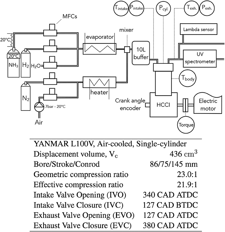
Figure 1. Setup and engine specifications used for ammonia-hydrogen combustion and exhaust analysis at various intake temperatures, equivalence ratios, and synthetic EGR conditions.
All the gaseous inputs are controlled by Brooks Mass Flow Controller (MFC) SLA-585X and the intake water for EGR emulation is controlled by a Bronkhorst Coriflow M14. When EGR is used, the evaporator outlet temperature is set at 150 °C. The air and nitrogen stream is heated to ensure the desired intake temperature (50–240°C). The intake temperature measurement is done by a type K thermocouple, right before the intake valve. Both intake gas lines (air + nitrogen and fuel + water) are merged at a gas mixer using a venturi effect. The venturi sections are designed to maximize the homogeneity for given flow ranges of the two streams, here corresponding the an equivalence ratio of 0.3 and 1 bar intake pressure. The venturi mixer is followed by a 10 liter buffer thank to ensure further homogenization and decreases the intake pressure fluctuations due to the intake valve motion. The in-cylinder pressure is measured by a relative piezoelectric AVL GH15D transducer, flush-mounted in the cylinder head, and its signal is amplified by a AVL FlexIFEM 2P2E. The intake and exhaust manifold pressures are measured with absolute piezoelectric KISTLER 4260 transducers. The engine output torque is measured by an HBM T40B while the electric motor ensures a constant 1,500 RPM engine speed. A TETHYS EXM400 UV spectroscopy system is used for the measurement of nitrogen compounds and the exhaust oxygen concentration is measured by a BOSCH LSU 4.9 lambda sensor. Finally, the crank angle is measured by a Heidenhain ROD 426 rotary encoder and used to synchronize all the acquired data, which is done by a National Instruments Compact Rio 9022.
The engine piston has been modified to a flat piston configuration, better suited for HCCI operation (Jiménez-Espadafor et al., 2009; Pedersen and Schramm, 2010), as it minimizes the piston crevice volume for a given compression ratio. Using the HCCI single-zone model developed and validated in Pochet et al. (2017a) with the kinetic mechanism from Song et al. (2016), and coupled to a Wiebe function-shaped combustion with a duration of 8 CAD, we obtained the required TBDC as a function of the engine compression ratio to allow neat ammonia operation, see Figure 2. To achieve neat ammonia operation in our limited intake temperature test bench, the effective compression ratio would need to be 27:1. Yet the optimal IMEP [and therefore Brake Efficiency (BE)] is reached at a compression ratio of 22:1 since that at higher values the equivalence ratio would be limited to meet the engine constraints (Pmax= 120 bar, MPRR = 12 bar/CAD). Moreover, hydrogen must still be operable without intensive ringing, and the ideal compression ratio (IMEP wise) for hydrogen has been demonstrated to be around 17:1-18:1 (Caton and Pruitt, 2009). The reason for avoiding ringing is that the generated high-amplitude pressure oscillations lead to oscillating wall heat fluxes and, due to the mass movement inside of the cylinder perturbating the thermal boundary layer, increased heat transfer (Broekaert et al., 2016). The main consequence is a decreased engine efficiency (as will be deduced from Figure 6). Therefore, a limited effective compression ratio of 22:1 is selected, even though it will not allow neat ammonia use.
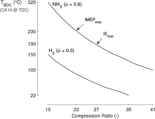
Figure 2. Coupling of a single-zone model (Pochet et al., 2017a) with a wiebe function (8 CAD combustion duration) to obtain sensible pressure curves, IMEP and IE performances. For an atmospheric intake pressure and the engine constraints of Pmax= 120 bar and MPRR = 12 bar/CAD, the highest achievable IMEP is obtained at 22:1. Increasing the compression ratio allows to increase the IE and decrease the required intake temperature but decreases the achievable equivalence ratio, hence the maximal IMEP.
Aiming at stationary applications, a constant 1,500 RPM is applied. Although neat ammonia operation was aimed at, the ammonia share could only be varied from 0 to 94%vol given the compression ratio and limited intake temperature. In order to have a map of the engine operating range, each blending ratio is assessed from misfire to ringing conditions by variation of the equivalence ratio. For this study, misfire is considered as a COVIMEP (Coefficient Of Variation of the Indicated Mean Effective Pressure) higher than 5% or a combustion efficiency lower than 90%.
In this study, the EGR used is synthetic and is defined in an unusual way and is therefore named Exhaust Gas Air Replacement (EGAR). Exhaust gases, emulated by water and nitrogen under their effective exhaust concentrations, are admitted in replacement of excess intake air. The EGAR rate is defined as the fraction of excess intake air replaced by exhaust gases (same mole quantity at the same temperature). Therefore, a 100% EGAR means that the mixture is in effective stoichiometric conditions without having impacted the fuel quantity. The general equation for ammonia-hydrogen combustion considered in this paper is therefore written as follows:
where ϕ0 is the equivalence ratio without considering the recirculated oxygen by the EGAR.
The intake pressure is set at 1 bar. No turbocharger has been used given the novelty of the ammonia-hydrogen blend under HCCI conditions. A mapping of the blend behavior is first to be obtained. The intake temperature is controlled in each run to maintain a CA50 (Crank Angle at which half of the fuel energy has been released) of 4 CAD aTDC, unless stated otherwise. In this paper, the fuel quantity present at the intake is expressed as Fuel Mean Effective Pressure (FuelMEP), the input fuel energy per displacement volume. It must be mentioned that hydrogen and ammonia have comparable engine mixture energy content. For example, for an equivalence ratio of 0.3, a neat hydrogen mixture possesses a 21.5 kJ/mol energy content compared to a 20.7 kJ/mol for neat ammonia. A summary of the operating conditions used in this paper is given in Table 1: 8 specific runs will be used to illustrate specific engine performances and the whole experimental set is used to illustrate the general ammonia-hydrogen behavior in HCCI engines.
The acquired raw data needs several post-processing steps before being suited for the engine performance analysis. The whole post-processing process used is described in details in Pochet et al. (2019b), but is summarized here. For each operating condition, 100 consecutive cycles are registered, with a resolution of 0.1 CAD. The in-cylinder pressure signal must be filtered and pegged to correct for noise and relativity of measurement. Then, the Top Dead Center (TDC) offset, the effective compression ratio, and the blow-by are computed and accounted for in the heat release analysis. The heat losses are calibrated to obtain a flat cumulative gross heat release curve before and after the combustion. Finally, the methodology used to compute the effective in-cylinder temperature is based on the work of Sjöberg et al. (and extended in Pochet et al., 2019b), as it depends on the operating conditions (e.g., fuel, equivalence ratio, etc.). As an example, the obtained correlation between Tin and TBDC for a motoring case is:
and for a fired case (50%vol.NH3 − 50%vol.H2 − ϕ = 0.35):
We obtained the uncertainties on the engine inputs and outputs of interest following the whole methodology derived by the authors in Pochet et al. (2019b), except for the uncertainties on the NH3, NO, and NO2 exhaust concentrations that are derived in the Supplementary Materials. The computed maximal and minimal uncertainties of the engine inputs and outputs (encompassing sensor calibrations, the acquisition system, the post-processing methods, and the statistical analysis data) encountered during the whole UCLouvain study are reported in Table 2. Given that the obtained uncertainties were fairly constant throughout the experimental runs, the uncertainty ranges shall not be reproduced on every figure.
The results are given and analyzed in this section. First, we study the influence of the ammonia-hydrogen blending ratio on the combustion and performance aspects. In addition, we assess the impact of fuel loading, intake temperature, and EGAR. Finally, based on these results, and using kinetic single-zone modeling to highlight the underlying causes of the observed phenomena, we propose guidelines toward improved ammonia HCCI engines.
As a first indicator of ammonia resistance to auto-ignition, the supplied BDC temperature throughout the experimental campaign is observed to increase exponentially with the increase in ammonia fraction in the fuel blend, see Figure 3. Low fractions of ammonia have no significant impact on the auto-ignition resistance of the whole mixture given the slow rise in BDC temperature. The increased resistance starts to appear at around 15%vol. of ammonia and then increases non-linearly, yet according to RCM exmeriments (Pochet et al., 2019a) the rise in ignition delay should be tapering off reaching neat ammonia.
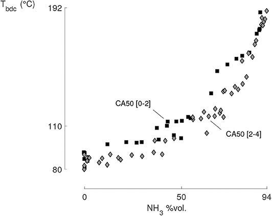
Figure 3. The required BDC temperature is increasing exponentially with the ammonia fraction in the fuel (all experimental points, CA50 timings between 0 and 4 CAD). From the operator point of view, an increase in the supplied intake temperature from 50 to 235°C was needed.
A better indicator of the auto-ignition resistance can be obtained from the encountered temperature and pressure 15 CAD before the TDC, T−15 and P−15 (Contino et al., 2017). These indicators take further account of the mixture heat capacity, wall heat exchanges, gas dynamics, and other phenomena at play during the compression. For the transition from neat hydrogen to 95%vol. ammonia, T−15 is increasing non-linearly and P−15 is strongly decreasing, see Figure 4. The reason for an increase in T−15 originates from the increased intake temperature, but the P−15 evolution derives at 70% from the increased heat exchange (less in-cylinder mass and increased temperature difference) and at 30% from the high heat capacity of ammonia, Cp, NH3, 293K = 35.2 J/mol/K, compared to hydrogen, Cp,H2, 293K = 28.8 J/mol/K. Not only the heat capacity of ammonia is higher than that of hydrogen, but it grows much faster with temperature: Cp, NH3, 1, 000K = 56.5 J/mol/K compared to Cp,H2, 1, 000K = 30.2 J/mol/K. The higher the ammonia loading is, the slower and lower the pressure and temperature will rise, therefore requiring increased BDC temperatures to allow ammonia auto-ignition.
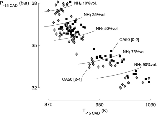
Figure 4. Pressure and temperature region 15 CAD before TDC (all experimental points, CA50 timings between 0 and 4 CAD). The resistance to auto-ignition of ammonia and its high heat capacity value explain why T−15 is increasing and P−15 is decreasing with higher ammonia fractions.
Increasing the ammonia fraction significantly increases the maximal gross IMEP, see Figure 5. From neat hydrogen to 95%vol. ammonia fraction, a 67% increase in IMEP has been obtained, with more than three quarter of that increase happening between 15 and 50%vol. of ammonia. Indeed, the required BDC temperature (see Figure 3) only increased after 15%vol. of ammonia but its final exponential increase is counter-balancing the IMEP gain from the achievable equivalence ratios. Nevertheless, Figure 5 can be a deceptive representation of the reality, as it hides many operating conditions to the reader.
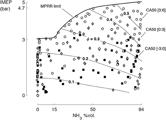
Figure 5. IMEP evolution as a function of the ammonia fraction in the fuel blend (all experimental points, CA50 timings between −3 and 6 CAD). Ammonia achieves 67% jump in gross IMEP compared to hydrogen. The IMEP only increases after 15%vol. in ammonia fraction, but tapers off after 50%vol. ammonia. The increased IMEP is characterized by a higher equivalence ratio achieved for identical CA50 timings.
A more explicit view of the IMEP potential and limitations is obtained by plotting it against the Maximum Pressure Rise Rate (MPRR), see Figure 6. As the equivalence ratio is increased to maximize the IMEP, the MPRR rises as well. Yet, as the MPRR rises above 10 bar/CAD, the heat and friction losses soar, eventually limiting the IMEP. We observe that ammonia helps reaching a higher IMEP for the same MPRR, meaning that ammonia damps the overall combustion rate. From this result and from Figure 5, we observe no difficulties operating neat hydrogen or 94%vol. ammonia before or after the TDC.
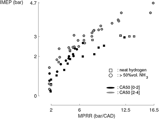
Figure 6. The achievable IMEP is tapering off as the MPRR increases due to an increased heat and friction losses (all experimental points). Ammonia allows higher IMEP due to a reduced MPRR for a given fuel loading and the major share of IMEP rise occurs between 15 and 50%vol. of ammonia.
As the MPRR further increases, ringing appears and the heat losses are further exacerbated. The engine is considered to be actively ringing when the Ringing Intensity (RI), a function of the maximal amplitude of the pressure signal filtered between 4 and 25 kHz and averaged for 100 consecutive cycles (Eng, 2002), is higher than 2 MW/m2. We choose this threshold level from the ringing noise generated by the engine. It corresponds to the safety level selected initially by Eng (2002). We observed that ammonia prevents ringing conditions and Figure 7 shows that 25%vol. ammonia concentrations are enough to significantly reduce the RI for a given MPRR. The authors showed in a previous study that increasing the intake pressure further helps reducing the RI (Pochet et al., 2017b), hence a considerable advantage for ammonia heavy-duty engines that could accept high intake pressures and fuel loadings.
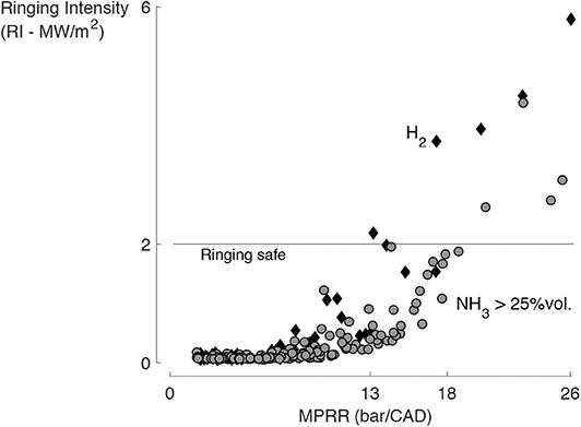
Figure 7. The RI is correlated to the MPRR, and ammonia reduces both the onset and the slope of the correlation (all experimental points).
More than knowing the IMEP limitations and drivers, it is interesting to understand the fundamental factors at play when ammonia damps the combustion. This insight will guide us for the ideal ammonia engine design. Increasing the ammonia fraction in the fuel blend (set #1) delays the combustion, see Figure 8. The set #1 is operated with fixed intake temperature and equivalence ratio (and therefore FuelMEP since ammonia and hydrogen have similar fuel-air mixture energy content). This delay arises both from ammonia slower kinetics and from its higher heat capacity leading to lower T−15 and P−15.
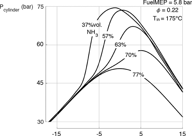
Figure 8. The combustion is delayed as the ammonia fraction is increased in the set #1, with constant FuelMEP, equivalence ratio and intake temperature.
To rigorously characterize the damping effect, the Heat Release Rate (HRR) for an increased ammonia fraction and constant CA50 and FuelMEP (set #2) are plotted in Figure 9. Ammonia can create a two-fold reduction in MPRR, with a combustion duration increase from 3 CAD to 7 CAD. Again, we observe that low fractions of hydrogen and low fractions of ammonia do not have significant effects on the heat release rate. In terms of ignition process, ammonia has a much longer initiation and termination period than hydrogen (more progressive slopes of the start and end of the HRR curve), hence a wider HRR. During that initiation period, some heat is released yet it is not sufficient to trigger the bulk auto-ignition. Similarly, the start and end of the HRR are less sharp. This relates to a “staged” combustion between hydrogen and ammonia where the pool of OH radicals initially created by hydrogen is first consumed by ammonia and its radicals, with eventually a 10 times smaller OH peak value, see Figures 10, 11.
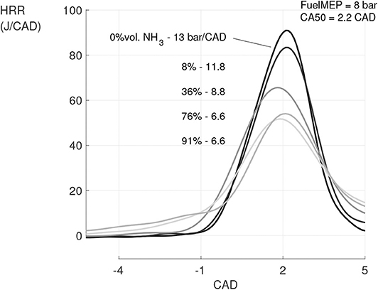
Figure 9. HRR evolution for set #2 having constant FuelMEP and CA50 as the ammonia fraction is increased from 0 to 91%vol. The maximum HRR and MPRR are reduced by half and the combustion start and end are getting further apart.
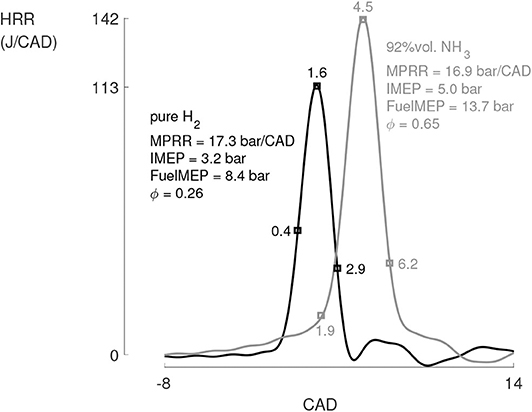
Figure 10. For equivalent MPRR and combustion timings, ammonia possesses a much longer initiation period than hydrogen, during which some heat is released but too few to trigger the bulk auto-ignition (set #3). The CA10, CA50, and CA90 are marked by squares on the HRR curves. For equivalent ignition timings and combustion durations, ammonia allows to increase the IMEP by more than 50% without impacting the indicated efficiency.
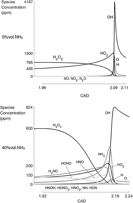
Figure 11. Intermediate species evolution for neat hydrogen (above) and for 40%vol. ammonia content (below). Without ammonia, a pool of H2O2 and HO2 is formed during the initiation phase, which is eventually consumed for the OH production. With ammonia, a lower OH peak is observed, together with a significant amount of non-reactive intermediate species being formed. Obtained using the HCCI single zone model developed in Pochet et al. (2017a) together with the mechanism from Mathieu and Petersen (2015).
With equivalent MPRR and similar combustion timings, the set #3 gathers the highest IMEP that we achieved with neat hydrogen and with ammonia-hydrogen blends: 3.2 and 5.0 bar, respectively, see Figure 10.
Using the same single-zone model as previously, the evolution (production and consumption) of the various radicals and intermediate species right before the combustion onset can be obtained, see Figure 11. This single-zone model has been developed and validated in Pochet et al. (2017a) with the sole purpose to precisely estimating HCCI auto-ignition timing. To do so, the heat loss model is tuned using the actual experiments so that the modeled in-cylinder conditions are representative of the ones of the hot core cylinder volume where the auto-igniton is first triggered hence predicting the experimentally observed CA5. Finally, the kinetic mechanism used is the one of Song et al. (2016) which is based on the DeNOx process and has been validated for high pressure (30–100 bar), low temperature (450–925 K) and lean ammonia combustion conditions. The first case to be simulated is for neat hydrogen and the second one for 40%vol. ammonia content. Both cases have the same combustion timing. Looking at the various kinetic mechanisms for ammonia and hydrogen, OH is the main radical responsible for the combustion initiation. A OH peak is observed at the time of peak HRR and CA50, as has been proven and used in Mathieu and Petersen (2015) and Pochet et al. (2019a). Looking at hydrogen kinetics, in the early initiation of combustion, H2O2 is formed, followed by HO2. Both molecules accumulation is then rapidly consumed to form OH, which triggers the main combustion. Many differences can be highlighted with ammonia. First, OH and HO2 peaks are smaller. Then, a significant quantity of intermediate species is formed, all consuming OH radicals for their production and decomposing into other non-reactive intermediate species. Consequently, ammonia combustion follows a higher number of steps. Finally, the long initiation period described in Figure 10 seems to be linked to the formation of NH2. A lot of OH radicals are consumed to do so, see the OH peak values from 11.
The combustion damping effect of ammonia can be explained through the evolution of the intermediate species formation with the increase in ammonia fraction, see Figure 12. As first indicators we use the peak concentration of OH, of H2O2+HO2, and of the remaining ammonia intermediate species. As a second indicator we use the CAD time between the OH peak and the H2O2 peak, Δtime, OH−H2O2. As the ammonia fraction increases, the OH and H2O2+HO2 peaks are decreasing. The essential radicals for fuel combustion are decreasing in concentration: OH concentration is divided by four with the first 15%vol. ammonia content while the H2O2+HO2 concentration is decreasing quite linearly. On the other hand, ammonia non-reactive intermediate species pool reaches a plateau after 15%vol. ammonia content. The initiation period between H2O2 and OH formation is extended and the reduced availability of OH radicals explains the slower combustion.
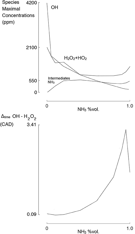
Figure 12. The OH and H2O2+HO2 peak concentrations are rapidly decreasing with the ammonia fraction, while the pool of ammonia non-reactive intermediate species is being formed. The initiation period between H2O2 and OH formation is extended.
Finally, the obtained indicated efficiency as a function of the ammonia content is observed constant at 37% (±0.8%, scattered) for all the experimental runs having a MPRR above 9 bar/CAD (i.e., ideal IMEP regarding power density). This result might seem counter intuitive since the heat capacity of ammonia has been shown to be higher and increase faster with temperature than hydrogen. Moreover, due to the higher intake temperature used with ammonia, heat losses undergo an absolute increase. Still, in a relative point of vue, the heat losses do not increase as fast as the gain in produced indicated work thanks to the higher equivalence ratios allowed by ammonia. This fact derives from the longer combustion durations observed with ammonia and similar combustion temperatures (see upcoming Figure 16), despite the increased IMEP.
The load range potential has already been assessed in Figure 5, but we need to assess the ease with which such range can be obtained (i.e., the engine controllability). The experimental set #4 is operated with a constant intake temperature of 82°C while the IMEP rises from 1.6 to 3.8 bar through an increased ammonia flow rate, see Figure 13. When the ammonia fraction is increased while the hydrogen flow rate is maintained, the combustion duration decreases by 50%. Therefore, in addition to ammonia slow kinetics, the FuelMEP significantly influences the combustion duration. Moreover, although the total fuel flow rate and ammonia fraction increase (and therefore the residual gas fraction temperature), the start of combustion remains the same due to a higher mixture heat capacity and longer ignition delay.
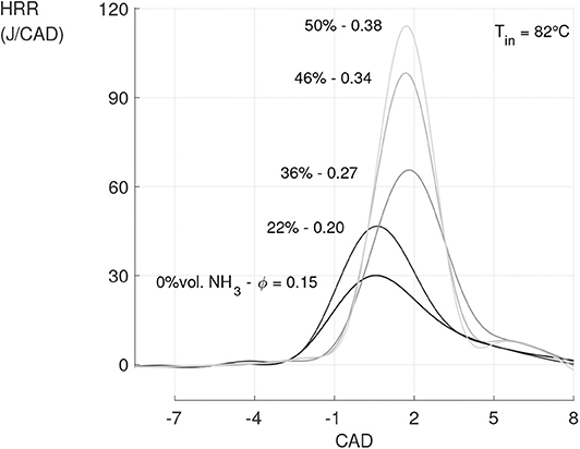
Figure 13. Simply increasing the ammonia flow rate while maintaining the intake temperature and hydrogen loading constant (set #4) can lead to a constant combustion timing, although the load has been more than doubled.
A deeper understanding is obtained through simulations, using the RCM single-zone effective adiabatic core volume model validated in Pochet et al. (2019a) with the same (Song et al., 2016) kinetic mechanism against ammonia-hydrogen RCM shots under the HCCI conditions of interest (high pressure, low temperature, lean conditions, 24:1 compression ratio). Two cases have been studied and reported in Figure 14: for the first one, the volume evolution of the RCM shot simulation as been fitted to showcase an effective compression ratio of 21.7:1 with a compression time of 35 ms and a second-half compression time of 4 ms, as in Pochet et al. (2019a). For the second case, the compression temperature and pressure have been fixed to 956.22 K and 75.57 bar, the ones obtained in the first case for neat hydrogen at an equivalence ratio of 0.2. For both cases, the ignition delay evolution has been studied as a function of an increase in ammonia fraction with equivalence ratios ranging from 0.2 to 0.5, see Figure 14. These results show that, for the first case study, the ammonia-hydrogen blending ratio can be adapted to control both the combustion timing and engine load thanks to the competing effects of equivalence ratio kinetics, heat capacities and ignition delay resistances. Thanks to the second case study, one can see that for the kinetic effect alone, increasing the ammonia fraction increases the ignition delay and increasing ammonia equivalence ratio decreases the ignition delay. Therefore, in the first case the increase in ignition delay with the equivalence ratio is only due to the heat capacity of ammonia, and not to the kinetics.
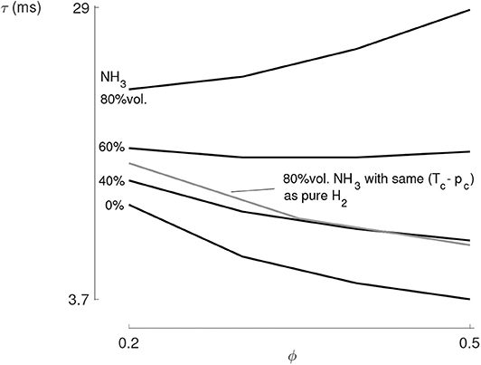
Figure 14. The ignition delay increases when the fuel loading is increased with an ammonia share higher than 60%vol., according to single zone effective adiabatic core volume RCM simulations. Yet when the heat capacity effect of ammonia is canceled by forcing the compression temperature and pressure, the ignition delay decreases with an increase in fuel loading.
Finally the hydrogen promotion threshold is sharp and should be considered when operating the engine, given the general control uncertainty and stability. The threshold concentration, which depends on the operating pressure and temperature conditions, is given in Figure 15.
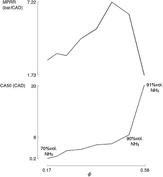
Figure 15. MPRR and CA50 evolution for set #5: constant intake temperature and hydrogen flow rate for a continuously increased ammonia flow rate. The ammonia auto-ignition promotion by hydrogen stops suddenly at a threshold concentration, which depends on the operating pressure and temperature conditions.
A major driver for the ideal engine design is the combustion efficiency, as it impacts both the overall efficiency and the pollutants emissions. The unburned ammonia fraction, defined as:
represents the combustion efficiency and was observed roughly constant with the evolution of the ammonia fuel fraction, see Figure 16. We observe the unburned ammonia percentage to span between 5 and 15%, with a strong correlation with the maximal combustion temperature iso-lines. These iso-lines are obtained from the runs themselves: all the dots located below the 1,600 K line have a maximal combustion temperature above 1,600 K. The slope of the iso-lines clearly highlight the evolution with the ammonia-hydrogen blending range of the correlation between the combustion efficiency and the temperature. To maintain the lowest possible unburned percentage, the maximal in-cylinder temperature has to rise with the ammonia fuel fraction, if not the unburned quantity can double. An increase in maximal in-cylinder temperature from 1,500 to 1,800 K is required to maintain a 5% unburned fraction when shifting from neat hydrogen to 95% of ammonia fraction. Still, the uncertainty on the maximal temperature being around 4% (or approximately ±70 K), care should be taken regarding the values of these limittemperatures.
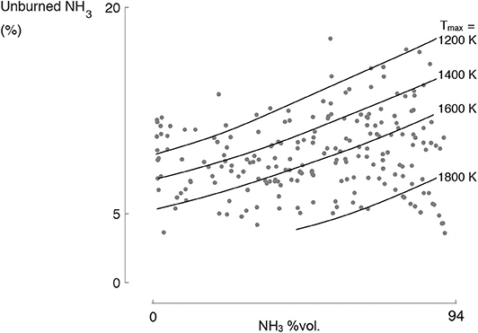
Figure 16. The ammonia unburned fraction is correlated to the ammonia fuel fraction and the maximal combustion temperature (Tmax) iso-lines (all the experiments). It does not go below 5% because of the piston crevices.
Regardless of the combustion temperature, no combustion has been observed with an unburned ammonia percentage below 5%. This is due to the high crevice volume that represents, at TDC, 4.85% of the chamber volume, and 3.64% of the chamber volume 10 CAD away from TDC. Indeed, the engine being initially designed for diesel direct injection in the piston bowl, the piston crevices were not minimized and are 7 mm high and 1 mm thick. Additionally, the extremely low Stroke-to-Bore ratio of this engine (S/B = 0.87) leads, together with a high compression ratio, to a pancake combustion chamber that has an extremely high heat exchange area. In our case, the clearance height at top dead center is only 3.3 mm, against a bore diameter of 86 mm. To minimize the heat exchange area (i.e., maximize the Volume-to-Surface area), the Stroke-to-Bore ratio has to be maximized (e.g., heavy-duty). This will help to minimize the crevices.
If one assumes the combustion to end at the CA90 timing, the unburned fraction that cannot be explained by the crevices can be linked to a wall quenching phenomenon. Therefore, at the CA90 timing, the unburned ammonia fraction can be expressed as follows:
where the quenching volume Vquenching is the volume made by a layer along the walls of the chamber volume where the quenching occurs. This layer has an assumed constant thickness, which is computed according to Equation (5). By the definition used, having a close-to-zero or even negative thickness simply means that part of the crevice-contained mixture has burned although the hypothesis is made it does not. The quenching thickness is displayed for the whole experimental campaign in Figure 17 as a function of the unburned ammonia fraction and as a function of the maximal combustion temperature. The close match of the correlation between the quenching thickness and the unburned ammonia fraction validates the CA90 choice as the reference point after which the unburned fuel is not converted anymore. The rough correlation seen between the quenching thickness and the maximum combustion temperature, despite the wide range of ammonia fuel fractions and intake temperatures considered, stems for the critical role of the combustion temperature. In order to significantly avoid quenching in the 1 mm thick crevices, the temperature inside must reach at least 1,700 K. Given the range in in-cylinder temperature required to make a difference in combustion efficiency, simply increasing the engine wall temperature by a couple of douzen degrees won't affect it directly, although it will affect the combustion timing and consequently the maximal in-cylinder temperature. Integrating that in addition to the long combustion duration, an early CA10 is preferred for ammonia combustion.
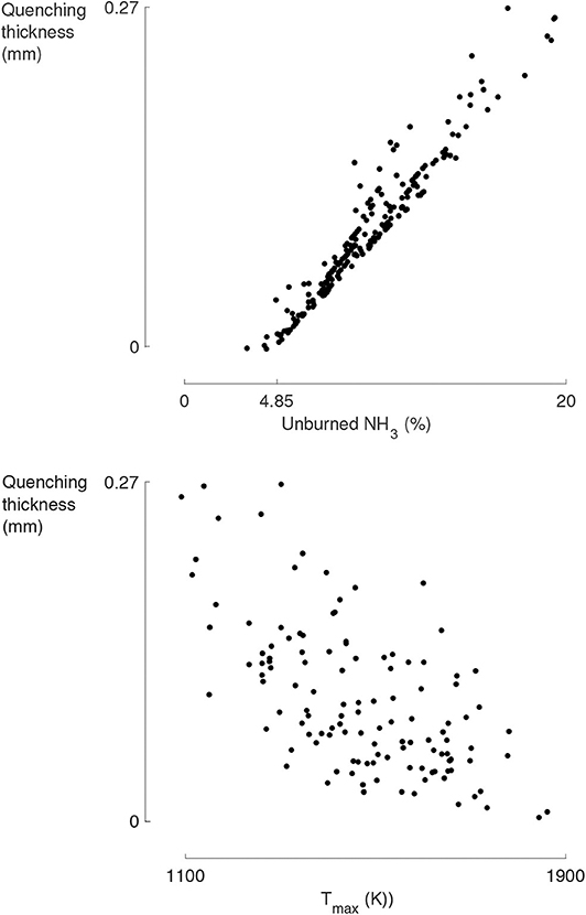
Figure 17. The quenching thickness spans for all the experimental runs from 0 to 0.27 mm as the unburned ammonia fraction increases from 4.85 to 20% (left) and as the maximum combustion temperature spans from 1,100 to 1,900 K (right). A maximal combustion temperature above 1,700 K shall help minimizing the crevice unburned fuel given the crevice thickness.
Compared to the low NOX levels (~50 ppm i.e., no thermal-NOX) that we observed for neat hydrogen, as soon as ammonia was fed to the engine, the NOX levels rose to above 1,000 ppm and kept increasing with the ammonia intake content, see Figure 18. These results are associated with CA50 = 4 ± 2 CAD and maximal combustion temperatures above 1,400 K but below 1,800 K. This highlight the NOX emissions to originate from fuel-nitrogen and not air-nitrogen thermal decomposition.
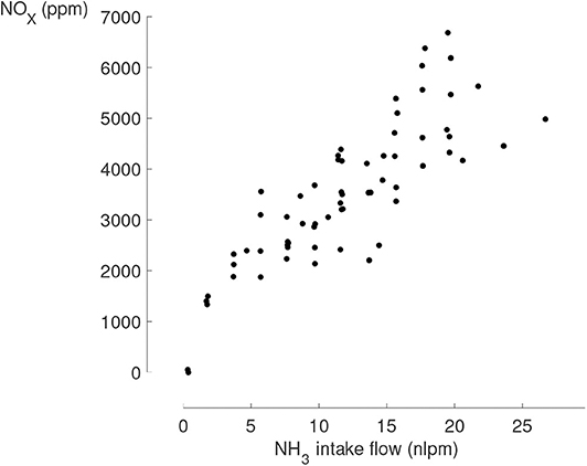
Figure 18. NOX emissions as a function of the ammonia intake flow (all the experiments, CA50 = 4 ± 2 CAD, Tmax > 1,400 K). As soon as ammonia is blended with hydrogen NOX emissions appear above 1,000 ppm, and keep increasing with the ammonia fuel flow, here expressed in normal liters per minute (nlpm).
Staying above 1,400 K is critical regarding emissions as the possible production of N2O is suspected. To investigate it, the following test has been performed: starting from a 50%vol. ammonia fuel blend (6 nlpm of ammonia), the intake temperature is progressively reduced hence delaying the combustion. The obtained NO emissions are displayed in Figure 19 and are observed to increase with a decreasing maximal combustion temperature below 1,450 K.
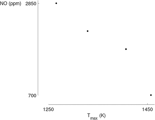
Figure 19. For a maintained ammonia and hydrogen intake flow rate of 6 nlpm and decreasing intake temperature (set #6), the NO emissions start to soar when the maximal combustion temperature decreases below 1,400 K. The UV spectrometer is suspected to be flawed by N2O, whose absorbtion spectrum is similar to that of NO.
It is not the NO formation that is impacted when decreasing the maximal combustion temperature below 1,400 K, but rather the decomposition of N2O. N2O is known to form in low temperature combustion and lean environments (Stone, 1985), but when the combustion temperature fails to reach the 1,400 K barrier, the formed N2O pool is never reduced, see Figure 20. As the N2O molecules absorb UV in a wide wavelength range (including 190–230 nm), the selected width from 214 to 216 nm for NO measurement in our UV spectrometer was probably measuring N2O in the present case.
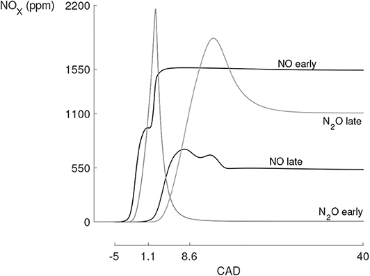
Figure 20. NO and N2O production-consumption curves for an early and a late combustion. The late combustion happens below 1,400 K which is insufficient to reduce the pool of N2O. Simulation results obtained with the previously used single-zone model with the kinetic mechanism from Mathieu and Petersen (2015).
Let us recall that the Exhaust Gas Air Replacement (EGAR) rate used in this paper is defined as the fraction of excess intake air replaced by exhaust gases (same mole quantity at the same temperature). Therefore a 100% EGAR means that the mixture is in effective stoichiometric conditions without having impacted the fuel quantity.
To fully characterize the EGAR impact on the engine emissions, one must look at all the NOX compounds and the combustion efficiency. First, the EGAR can have up to a three-fold reduction effect on the NO emissions when pushed to a 80% rate, see Figure 21. This effect oughts to the reduced oxygen availability which favors the production of N2 instead of NOX from the unbounded fuel-nitrogen. Although the reduction could be greater for higher EGAR rates, a stable combustion could not maintained above 80% of EGAR. Indeed, EGAR lowers the combustion temperature and, considering the high impact of EGAR on the mixture heat capacity in addition to that of ammonia, it becomes a hurdle to achieve auto-ignition and maintain combustion temperatures that minimize the quenching thickness. As a consequence, EGAR was not able to further increase the IMEP of the ammonia-hydrogen blend in addition to reducing NOX emissions.
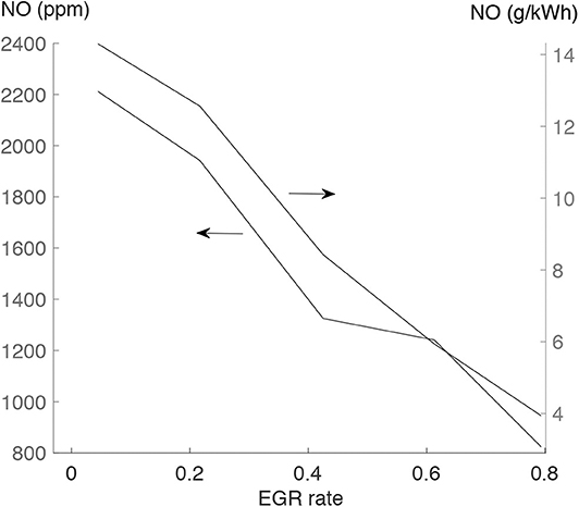
Figure 21. A factor three in NO reduction can be achieved thanks to EGAR, for early combustion timings and prior to the N2O threshold (set #7, constant 33%vol. ammonia fraction with an equivalence ratio increasing from 0.19 to 0.26 to maintain proper combustion timing).
Finally, the EGAR negatively impacts the NO2 emissions, see Figure 22, regardless of the ammonia blending ratio.
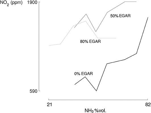
Figure 22. NO2 emissions increase as the ammonia fraction is raised, and the EGAR impacts them negatively (set #8 with a constant equivalence ratio of 0.22).
Although EGAR can have a drastic impact on NOX emissions, if no combustion temperature enhancing technique or quenching thickness reduction techniques is used (such as turbocharging or wall coating) the overall effect can be mitigated.
In the case of ammonia HCCI combustion, various after-treatment techniques could be used given that specific exhaust conditions are met (depending on the operating conditions).
The most obvious technique is Selective Catalytic Reduction (SCR) as it can be used whatever the oxygen concentration to reduce NOX and N2O, with conversion efficiencies at 100% for the temperature window 300–450 °C. SCR requires the use of an ammonia-based substance to obtain the following ratio in the exhaust mixture: (Jiang et al., 2016). This is usually seen as an inconvenience since an additive has to be supplied, yet in our case we could take profit from the unburned ammonia emissions. In practice, the NH3 to NOX ratio is slightly higher than 1 to ensure total NOX conversion and an AMmonia Oxidizer (AMOX) catalyst is therefore used to convert the ammonia leftovers from the SCR (Mendoza-villafuerte et al., 2017). With a constant combustion efficiency of 95%, the ammonia exhaust concentration evolved from 0 to 6,000 ppm hence evolving accordingly to the NOX concentration, see Figure 18. With an improved crevice design hopefully rendering a two-fold reduction in unburned fuel, some NH3 shall be added to maintain the ammonia to NOX ratio. Regarding the SCR operational temperatures, for the performed experimental campaign the obtained exhaust temperature (measured in the non-insulated exhaust manifold) evolved from 180 °C for neat hydrogen to 330 °C for 95%vol. ammonia content. The use of a SCR to perform a combined NH3-NOX reduction is therefore at reach for the considered application, coupled to an AMOX, yet it would require an SCR heater if the ammonia intake content is reduced below 75%vol.
Secondly, Lean NOX Trap (LNT) can be used whatever the oxygen exhaust concentration to adsorb NO and NO2, and uses frequent rich-combustion cycles to regenerate the trap by reducing NOX to nitrogen and water with an average 2% fuel economy cost. LNT reach a total NOX adsorption-conversion when used at 250 °C, which would make it compatible in our case with ammonia intake contents lower than 75%vol. Still, LNT only achieve partial N2O adsorption-conversion and generate NH3 as a bi-product during the regeneration. However, recent studies have shown practical evidence of the beneficial combination of LNT and SCR in series: as the NOX reduction is split between the LNT and SCR, the fuel penalty can be mitigated compared to pure LNT, the ideal operation temperature of both systems is more flexible and in the 200–300 °C range, and total conversion of NOX-N2O-NH3 is achieved (Wang and Crocker, 2012; Wittka et al., 2015).
Finally, Three Way Catalytic converters (TWC) can be used to convert NOX emissions with efficiencies above 95%, yet requiring stoichiometric operations and exhaust temperatures above 300–350 °C to reach such efficiencies. The reason for mentioning the use of TWC for a lean ammonia HCCI engine is that they have been shown to render equivalent conversion efficiencies for NH3 in addition to NOX emissions (Koike et al., 2016). Regarding the operation of an HCCI engine under stoichiometric conditions, or more precisely without oxygen at the exhaust, achieving a 100% EGAR rate operation would meet such criterion.
In this paper, the ammonia-hydrogen blend has been successfully experimented in a 22:1 effective compression ratio HCCI engine, from neat hydrogen to 94%vol. ammonia fraction. The ammonia-hydrogen fraction do not influence the indicated efficiency significantly, still the other engine outputs were greatly modified by the blending ratio.
First, ammonia slow kinetics and radical exchange with hydrogen allow to damp the combustion intensity at ammonia fractions as low as 20%. Further increasing the ammonia share allowed to reach higher equivalence ratios and IMEP. A global 50% increase in IMEP compared to neat hydrogen is possible, with 5.0 bar. Moreover, given the used compression ratio, hydrogen was closer from its ideal power density CR than ammonia.
For a maximized ammonia combustion efficiency, the main operating parameter to consider is the maximum combustion temperature (and limited gradient toward the engine wall). It is enhanced through high fuel loads, obtained from turbocharging and high equivalence ratios. To avoid bulk quenching, maximum combustion temperatures of 1,600 K were required for neat hydrogen and 1,800 K for neat ammonia. Such conditions were met for 50 and 90%vol. ammonia fraction under 4.5 and 5.0 bar IMEP, respectively, and allowed combustion efficiencies of 95%. The remaining unburned emissions were shown to be linked to the crevice volume, as it was estimated to 5% of the TDC volume.
As soon as ammonia was present in the fuel, fuel-NOX emissions above 580 ppm have been observed, against 50 ppm for neat hydrogen. Still, these emissions were decreasing with a reduced oxygen availability (more than a two-fold reduction when using 80% EGAR). Yet EGAR impacted other combustion aspects: overall reactivity and combustion efficiency. Ammonia already possessing slow kinetics, the use of EGAR must be assorted with a combustion promoter: either hydrogen (contrary to our goal), or equivalence ratio (limited in our case), or intake temperature (limited in our case), or turbocharging.
Other noticeable results can be mentioned. For maximal combustion temperatures below 1,400 K, N2O is being produced, which must be avoided at all costs. For combustion happening mainly in the expansion phase, the combustion pathways of ammonia were shown to stop the reduction of intermediate NOX due to a faster decrease in temperature. Finally, the ammonia-hydrogen blending ratio selection is a practical and faster way of load and combustion timing control than through intake temperature variation.
Although another set of engine constraints (MPRR, Pmax, Pin) would imply another ideal compression ratio and engine performances, the obtained experimental observations still allow to draw the following conclusions:. For a given compression ratio, determining the ideal ammonia-hydrogen blending ratio would be a techno-economic trade-off decision based on the obtained results. 75% of the IMEP increase potential happens before 50%vol. of ammonia content in the fuel. Still, the higher the hydrogen fraction the lower the required maximal combustion temperature to avoid bulk quenching (impacting the design of the aftertreatment system) and the lower the required intake temperature (impacting the design of the heat recovery for the intake-charge heating). Parameters that are to consider to limit crevice unburned emissions are a minimized crevice volume and a high stroke-to-bore ratio. Extensive work is needed on fuel-NOX primary reduction measures and after-treatment ways. Regarding primary measures, this work suggests that boosted conditions with maximized stroke-to-bore ratios should be aimed at, to allow higher EGR rates at maintained combustion temperatures.
The datasets generated for this study are available on request to the corresponding author.
MP, HJ, and FC participated fully to the results obtention, analysis, and paper writing. All authors contributed to the article and approved the submitted version.
The investigations presented in this paper are obtained within a doctoral research funded by the FRIA (MP, fellow # 17513, FRS-FNRS, Belgium) and supported by ENGIE Electrabel.
The authors declare that the research was conducted in the absence of any commercial or financial relationships that could be construed as a potential conflict of interest.
The authors would finally like to acknowledge and thank the technical support of Axel Jottard, Frank Hesbois, Yan Liu, François Vercheval, Arnaud Lion, and Julien Vervotte from the iMMC laboratories.
The Supplementary Material for this article can be found online at: https://www.frontiersin.org/articles/10.3389/fmech.2020.00043/full#supplementary-material
Bhaduri, S., Berger, B., Pochet, M., Jeanmart, H., and Contino, F. (2017). HCCI engine operated with unscrubbed biomass syngas. Fuel Process. Technol. 157, 52–58. doi: 10.1016/j.fuproc.2016.10.011
Boretti, A. A. (2012). Novel heavy duty engine concept for operation dual fuel H2-NH3. Int. J. Hydrogen Energy 37, 7869–7876. doi: 10.1016/j.ijhydene.2012.01.091
Broekaert, S., De Cuyper, T., Chana, K., De Paepe, M., and Verhelst, S. (2016). “The effect of ringing combustion on the wall heat flux during HCCI operation,” in FISITA Automotive Conference 2016 (Busan). Available online at: http://hdl.handle.net/1854/LU-8500932
Caton, P. A., and Pruitt, J. T. (2009). Homogeneous charge compression ignition of hydrogen in a single-cylinder diesel engine. Int. J. Engine Res. 10, 45–63. doi: 10.1243/14680874JER02208
Cinti, G., Frattini, D., Jannelli, E., Desideri, U., and Bidini, G. (2017). Coupling Solid Oxide Electrolyser (SOE) and ammonia production plant. Appl. Energy 192, 466–476. doi: 10.1016/j.apenergy.2016.09.026
Contino, F., Dagaut, P., Halter, F., Masurier, J. B., Dayma, G., Mounaïm-Rousselle, C., et al. (2017). Screening method for fuels in homogeneous charge compression ignition engines: application to valeric biofuels. Energy Fuels 31, 607–614. doi: 10.1021/acs.energyfuels.6b02300
Duynslaegher, C. (2011). Experimental and numerical study of ammonia combustion (Ph.D. thesis). UCLouvain, Ottignies-Louvain-la-Neuve, Belgium.
Eng, J. A. (2002). Characterization of Pressure Waves in HCCI Combustion. Society of Automotive Engineers Technical Paper 2002-01-2859. doi: 10.4271/2002-01-2859
European Commission (2007). Reference Document on Best Available Techniques (BAT) for the Manufacture of Large Volume Inorganic Chemicals-Ammonia, Acids and Fertilisers. Technical Report.
Frigo, S., and Gentili, R. (2013). Analysis of the behaviour of a 4-stroke Si engine fuelled with ammonia and hydrogen. Int. J. Hydrogen Energy 38, 1607–1615. doi: 10.1016/j.ijhydene.2012.10.114
Gardiner, M. (2009). DOE Hydrogen and Fuel Cells Program: Hydrogen Storage. U.S Department of Energy, 1–6.
Glarborg, P., Jensen, A. D., and Johnsson, J. E. (2003). Fuel nitrogen conversion in solid fuel fired systems. Prog. Energy Combust. Sci. 29, 89–113. doi: 10.1016/S0360-1285(02)00031-X
Gomes Antunes, J. M., Mikalsen, R., and Roskilly, A. P. (2008). An investigation of hydrogen-fuelled HCCI engine performance and operation. Int. J. Hydrogen Energy 33, 5823–5828. doi: 10.1016/j.ijhydene.2008.07.121
Grannell, S. M., Assanis, D. N., and Bohac, S. V. (2006). “The operating features of a stoichiometric, ammonia and gasoline dual fueled spark ignition engine,” in Proceedings of ASME International Mechanical Engineering Congress and Exposition (Chicago, IL), 1–13. doi: 10.1115/IMECE2006-13048
Grannell, S. M., Assanis, D. N., Gillespie, D. E., and Bohac, S. V. (2009). “Exhaust emissions from a stoichiometric, ammonia and gasoline dual fueled spark ignition engine,” in Proceedings of the ASME Internal Combustion Engine Division (Milwaukee, WI), 1–7. doi: 10.1115/ICES2009-76131
Hedegaard, K., and Meibom, P. (2012). Wind power impacts and electricity storage - A time scale perspective. Renew. Energy 37, 318–324. doi: 10.1016/j.renene.2011.06.034
Jiang, N., Lu, N., and Shang, K. (2016). High-efficiency removal of NO x from flue gas by multitooth wheel-cylinder corona discharge plasma facilitated selective catalytic reduction process. IEEE Trans. Plasma Sci. 44, 2738–2744. doi: 10.1109/TPS.2016.2609140
Jiménez-Espadafor, F. J., Garcia, M. T., Herrero, J. A., and Villanueva, J. A. (2009). Effect of turbulence and external exhaust gas recirculation on HCCI combustion mode and exhaust emissions. Energy Fuels 23, 4295–4303. doi: 10.1021/ef900330x
Jülch, V. (2016). Comparison of electricity storage options using levelized cost of storage (LCOS) method. Appl. Energy 183, 1594–1606. doi: 10.1016/j.apenergy.2016.08.165
Koike, M., Miyagawa, H., Suzuoki, T., and Ogasawara, K. (2016). Ammonia as a hydrogen energy carrier and its application to internal combustion engines. J. Combust. Soc. Japan 58, 99–106. doi: 10.20619/jcombsj.58.184_99
Kramlich, J. C., and Linak, W. P. (1994). Nitrous oxide behavior in the atmosphere, and in combustion and industrial systems. Prog. Energy Combust. Sci. 20, 149–202. doi: 10.1016/0360-1285(94)90009-4
Mathieu, O., and Petersen, E. L. (2015). Experimental and modeling study on the high-temperature oxidation of Ammonia and related NOx chemistry. Combust. Flame 162, 554–570. doi: 10.1016/j.combustflame.2014.08.022
Mendoza-villafuerte, P., Suarez-bertoa, R., Giechaskiel, B., Riccobono, F., Bulgheroni, C., Astorga, C., et al. (2017). Science of the Total Environment NOx, NH3, N2O and PN real driving emissions from a Euro VI heavy-duty vehicle. Impact of regulatory on-road test conditions on emissions. Sci. Tot. Environ. 609, 546–555. doi: 10.1016/j.scitotenv.2017.07.168
Morgan, E. R. (2013). Techno-economic feasibility study of ammonia plants powered by offshore wind (Ph.D. thesis). University of Massachusetts, Amherst, MA.
Pedersen, T. D., and Schramm, J. (2010). Reduction of HCCI Combustion Noise Through Piston Crown Design. Rio de Janeiro: SAE Technical Paper 2010-01-1487. doi: 10.4271/2010-01-1487
Pochet, M., Dias, V., Jeanmart, H., Verhelst, S., and Contino, F. (2017a). “Multifuel CHP HCCI engine towards flexible power-to-fuel: numerical study of operating range,” in Energy Procedia, Vol. 105, (Beijing), 1532–1538. doi: 10.1016/j.egypro.2017.03.468
Pochet, M., Dias, V., Moreau, B., Foucher, F., Jeanmart, H., and Contino, F. (2019a). Experimental and numerical study, under LTC conditions, of ammonia ignition delay with and without hydrogen addition. Proc. Combust. Instit. 37, 621–629. doi: 10.1016/j.proci.2018.05.138
Pochet, M., Jeanmart, H., and Contino, F. (2019b). Uncertainty quantification from raw measurements to post-processed data: a general methodology and its application to an Homogeneous-Charge Compression-Ignition engine. Int. J. Engine Res. doi: 10.1177/1468087419892697
Pochet, M., Truedsson, I., Foucher, F., Jeanmart, H., and Contino, F. (2017b). Ammonia-Hydrogen Blends in Homogeneous-Charge Compression-Ignition Engine. Society of Automotive Engineers Technical Paper 2017-24-0087. doi: 10.4271/2017-24-0087
Reiter, A. J., and Kong, S.-C. (2011). Combustion and emissions characteristics of compression-ignition engine using dual ammonia-diesel fuel. Fuel 90, 87–97. doi: 10.1016/j.fuel.2010.07.055
Reiter, A. J., and Kong, S. C. (2008). Demonstration of compression-ignition engine combustion using ammonia in reducing greenhouse gas emissions. Energy Fuels 22, 2963–2971. doi: 10.1021/ef800140f
Ryu, K. H., Zacharakis-Jutz, G., and Kong, S.-C. (2013). Effects of Fuel Compositions on Diesel Engine Performance Using Ammonia-DME Mixtures. Society of Automotive Engineers Technical Paper 2013-01-1133. doi: 10.4271/2013-01-1133
Song, Y., Hashemi, H., Christensen, J. M., Zou, C., Marshall, P., and Glarborg, P. (2016). Ammonia oxidation at high pressure and intermediate temperatures. Fuel 181, 358–365. doi: 10.1016/j.fuel.2016.04.100
Stenlåås, O., Christensen, M., Egnell, R., Johansson, B., and Mauss, F. (2004). Hydrogen as Homogeneous Charge Compression Ignition Engine Fuel. Society of Automotive Engineers Technical Paper 2004-01-19. doi: 10.4271/2004-01-1976
Stone, R. (1985). Introduction to Internal Combustion Engines, 4th Edn. Basingstoke: Palgrave MacMillan. doi: 10.1007/978-1-349-17910-7
Teichmann, D., Arlt, W., and Wasserscheid, P. (2012). Liquid Organic Hydrogen Carriers as an efficient vector for the transport and storage of renewable energy. Int. J. Hydrogen Energy 37, 18118–18132. doi: 10.1016/j.ijhydene.2012.08.066
Van Blarigan, P. (2000). Advanced Internal Combustion Engine Research. 2000 U.S DOE Hydrogen Program Review, 639–656.
Wang, H., Zhou, X., and Ouyang, M. (2016). Efficiency analysis of novel Liquid Organic Hydrogen Carrier technology and comparison with high pressure storage pathway. Int. J. Hydrogen Energy 41, 18062–18071. doi: 10.1016/j.ijhydene.2016.08.003
Wang, J., and Crocker, M. (2012). N 2O mitigation in a coupled LNT-SCR system N 2 O Mitigation in a Coupled LNT-SCR System. Catal. Lett. 142, 1167–1174. doi: 10.1007/s10562-012-0889-y
Keywords: ammonia, hydrogen, HCCI, EGR, NOX
Citation: Pochet M, Jeanmart H and Contino F (2020) A 22:1 Compression Ratio Ammonia-Hydrogen HCCI Engine: Combustion, Load, and Emission Performances. Front. Mech. Eng. 6:43. doi: 10.3389/fmech.2020.00043
Received: 20 December 2019; Accepted: 19 May 2020;
Published: 26 June 2020.
Edited by:
Evangelos G. Giakoumis, National Technical University of Athens, GreeceReviewed by:
Choongsik Bae, Korea Advanced Institute of Science and Technology, South KoreaCopyright © 2020 Pochet, Jeanmart and Contino. This is an open-access article distributed under the terms of the Creative Commons Attribution License (CC BY). The use, distribution or reproduction in other forums is permitted, provided the original author(s) and the copyright owner(s) are credited and that the original publication in this journal is cited, in accordance with accepted academic practice. No use, distribution or reproduction is permitted which does not comply with these terms.
*Correspondence: Maxime Pochet, cGNoQGVjYW0uYmU=
Disclaimer: All claims expressed in this article are solely those of the authors and do not necessarily represent those of their affiliated organizations, or those of the publisher, the editors and the reviewers. Any product that may be evaluated in this article or claim that may be made by its manufacturer is not guaranteed or endorsed by the publisher.
Research integrity at Frontiers

Learn more about the work of our research integrity team to safeguard the quality of each article we publish.