 Ezgi Orhan
 Mert Yuksel
 Atakan B. Ari
 Cenk Yanik
 Utku Hatipoglu1
 Ahmet Murat Yağci
 M. Selim Hanay
95% of researchers rate our articles as excellent or good
Learn more about the work of our research integrity team to safeguard the quality of each article we publish.
Find out more
ORIGINAL RESEARCH article
Front. Mech. Eng. , 10 June 2020
Sec. Micro- and Nanoelectromechanical Systems
Volume 6 - 2020 | https://doi.org/10.3389/fmech.2020.00037
This article is part of the Research Topic Nanomechanical Sensors View all 5 articles
Nanoelectromechanical systems (NEMS) have been utilized as sensitive mass sensors in many applications such as single cell characterization, volatile organic biomarker detection and single molecule mass spectrometry. Using the frequency shift detection, mass of single analytes can be resolved. Mass detection sensitivity can be further improved by accurate measurement of the position, unlocking extra capabilities in nanoscale positioning and manipulation applications. Here, we studied the position sensing performance of two-mode NEMS resonators during detection of single 20 nm gold nanoparticles (GNPs). By recording the position of each particle with frequency shift sensing, the position detection accuracy was evaluated for different beam models and the results are validated by SEM imaging our results indicate that the position sensing accuracy, and therefore the mass sensing accuracy, of nanomechanical resonators depends critically on the use of appropriate beam models.
The potential of mass sensing with NEMS devices was recognized in the early 2000s (Ekinci et al., 2004a,b; Ilic et al., 2004). Mass resolution at the zeptogram level was demonstrated a few years later (Yang et al., 2006) with top-down NEMS devices. Meanwhile, bottom-up NEMS devices have also been used in significant demonstrations such as obtaining atomic mass through shot noise statistics (Jensen et al., 2008), detecting single molecules (Chiu et al., 2008; Lassagne et al., 2008), and eventually reaching yoctogram-level resolution (Chaste et al., 2012). In these studies, the analyte has been modeled as a soft particle with a fixed stiffness (Tamayo et al., 2006; Park et al., 2010; Malvar et al., 2016). As a result, the frequency shifts obtained in the experiments could be directly related to the mass of the analyte. However, a recurring problem in early experiments was the position-dependent sensitivity of the NEMS device. Positional-sensitivity comes about due to the non-uniform vibration profile of the flexural modes in device structures commonly used in NEMS, such as cantilevers or doubly-clamped beams. As the vibration profile, i.e., mode shape, changes along the device, analytes arriving at sensor locations with larger motional amplitude will induce a larger frequency shift than identical analytes arriving at locations with smaller vibration amplitude, e.g., near an anchor point or a node (Ramos et al., 2006, 2007; Stachiv et al., 2012).
Positional sensitivity of different modes was recognized early on with microcantilevers (Dohn et al., 2005; Ghatkesar et al., 2007). Later on, multiple modes were utilized to resolve both mass and position of the analyte (Dohn et al., 2007, 2010; Naik et al., 2009; Hanay et al., 2012; Bouchaala et al., 2016). The most straightforward way to understand this technique is that there are two unknowns (mass and position), hence two independent equations should be obtained. Frequency measurement in each mode provides one such independent equation. This technique has been colloquially called the two-mode technique since the mass of the analyte can be determined if two modes are used in a doubly-clamped beam. In order to utilize this technique several assumptions have to be made. First, the analytes are treated as point masses, mechanical modes are orthogonal to each other and the mode shapes are not affected by particles landed on the beam. Further improvement on the two-mode technique by using even more modes was achieved and mass distribution of the analytes were obtained (Dohn et al., 2010; Biswas et al., 2015; Hanay et al., 2015; Heinrich and Dufour, 2015; Olcum et al., 2015; Sader et al., 2018; Jia and Feng, 2019; Martín-Pérez et al., 2019; Dilena et al., 2020)—an approach called Inertial Imaging. It should be noted that two-mode theory and Inertial Imaging capitalizes on the geometrical diversity of the mode shapes; hence, these ideas can be extended to sensors with distinct mode shapes functioning in other domains. For instance, position sensing of droplets in a microfluidic channel, as well as single cell sensing, have been demonstrated using microwave resonant sensors operated with two modes simultaneously (Kelleci et al., 2018). Another general approach to obtain mass information is to circumvent the issue of position-dependent responsivity altogether by using different device designs (Lobontiu et al., 2006; Park et al., 2010; Sansa et al., 2020).
Although the position information of an analyte plays a critical role in determining the mass, reports on investigating the position-resolution performance of NEMS sensors have been lacking so far. With micro-electromechanical systems and using a gold particle with 0.9 micrometer radius, the relationship between position and modal sensitivity was studied in an earlier work (Dohn et al., 2007). More recently, the location of cells landing on a microscale mechanical platform was also demonstrated (Malvar et al., 2016) in an experiment where the stiffness of the analyte was also considered in the model. In this work, we took a different approach to obtain a large number of data points to sense single nanoparticles on the NEMS. The experiments were done at room temperature and laser desorption was used to deliver the nanoparticles. The location of each particle was calculated in real-time by the two-mode technique. After each subsequent adsorption of several nano-particles, the device was removed from the experimental setup for SEM characterization where the locations of the adsorbed nanoparticles are detected individually. The number of detected particles in each cycle was limited to 5 typically (and 20 at most so) to prevent any ambiguity due to crowding while mapping the events detected by NEMS and the particles observed under SEM. This protocol was repeated until sufficient data points were obtained to have a meaningful statistical distribution. We then compared the position measurement results based on mode shapes calculated from different models to determine the accuracy of the detected position of the nanoparticles. For FEM simulations, SiN doubly clamped beam was modeled at two different lengths, 15 and 20 μm and the gold electrodes on top were accounted for in the model as well. The material parameters for standard COMSOL library was used; relevant material parameters are listed in Table 2.
The NEMS chip is positioned in a table-top UHV chamber (Kurt Lesker) where electrical and optical access are provided for transduction of NEMS and desorption of gold nanoparticles, respectively (Figure 1A). The experiments are conducted under high vacuum conditions (~10−8 Torr) to reduce molecular interactions and increase the quality factor. The experimental setup for this study is based on an earlier work where backside desorption method was implemented (Yuksel et al., 2019). A nitrogen laser (NL 100, Stanford Research Systems) with the wavelength of 337 nm and energy of 176 μJ per pulse is used to perform laser-induced desorption of gold nanoparticles from the surface. Since the laser provides a wide, rectangular beam, focusing is necessary to increase its energy. A lens (with focal distance of 200 mm) is mounted in front of the laser beam shutter and the laser is placed on a manual XYZ positioner in order to align the laser beam with respect to the active area of the NEMS chip. A glass slide containing the analyte molecules can be scanned in-plane using a UHV XY Scanner (Design Multibase, Kurt Lesker). Two stepper motors (McLennan) controlled with a PIC microcontroller provide the scanning action of the XY stage. A colloidal solution of gold nanoparticles (Sigma Aldrich) with nominal diameter of 20 nm were chosen for this study, since their high density and conductivity render them suitable both for inertial and SEM measurements. After depositing GNP on a glass slide with the help of a micropipette without applying any dilution and waiting for the slide to dry completely (typically 2 h), the glass slide is introduced into an aluminum holder piece inside the chamber. To perform laser-induced desorption, the NEMS chip is mounted on the stage of a flow cryostat (Janis) placed inside the chamber, although the experiments were carried out at room temperature. The glass slide containing the sample is arranged in parallel to the NEMS resonator with the help of the holder piece attached on an arm mounted on the XY stage. Systematic scanning of the XY stage is important to span the surface of the glass slide and find the hot spots. Doubly-clamped SiN beam resonators (with large thin-film stress), 15 and 20 μm in length, 370 nm in width and 100 nm in thickness are used in different runs (Figure 1B). The fabrication process of the SiN NEMS resonators was reported earlier (Ari et al., 2018). In short, two electron beam lithography steps followed by metal deposition were used to define the gold electrodes and the beam geometry (via a copper etch mask) on a commercial silicon wafer with 100 nm SiN top layer. A succession of anisotropic and isotropic etched, followed by the removal of copper etch mask resulted in the NEMS devices used here. The NEMS resonator is transduced by thermoelastic driving and piezoresistive detection via gold nano-loop electrodes located near both ends of the beam. A.C. voltage at half of the resonance frequency of the beam is applied to the drive port in order to actuate the resonator. Due to the different thermal expansion coefficients of the beam substrate and the electrode (i.e., silicon nitride and gold), thermal stress occurs and exerts a bending moment on the beam. At the same time due to geometric piezoresistivity, resistance of the detection electrode changes with the flexural motion of the beam, which can be measured by applying an A.C. bias voltage at the resonance frequency (Bargatin et al., 2007; Beardslee et al., 2010; Ari et al., 2018). The resonance frequency values of the NEMS devices are listed in Table 1. Allan deviations of ~1.5 × 10⁻⁶ are typically obtained for both modes.
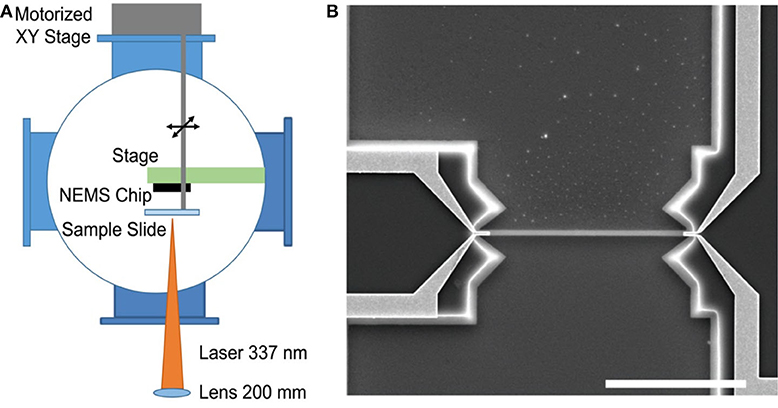
Figure 1. Experimental setup. (A) Ultra high vacuum (UHV) system equipped with a motorized stage to scan the sample slide containing nanoparticles. The laser used for desorption is positioned outside the chamber and focused through an optical access on the vacuum chamber. (B) SEM image of a typical doubly-clamped beam resonator used in the experiments. The scale bar is 10 μm.
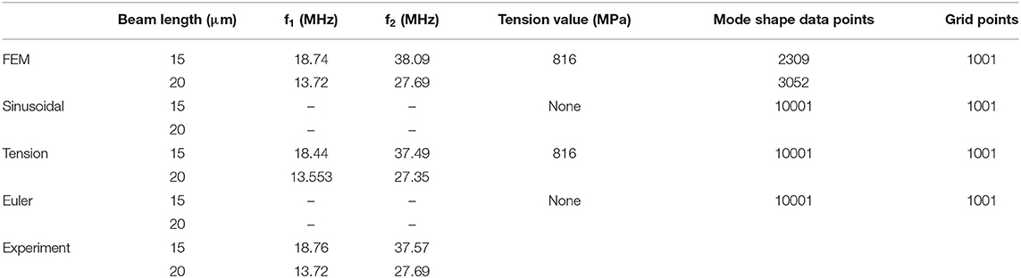
Table 1. Resonance frequencies.
To measure the frequency shifts due to the adsorbed analytes, both the first and second modes of the resonator are tracked individually by phase-locked–loops (PLL). A typical time trace of a NEMS nanoparticle sensing experiment is shown in Figure 2A where each GNP adsorbed by the sensor induces frequency shifts in two-modes. After collecting several such particles and calculating the positions using the two-mode theory, the NEMS chip is removed for SEM characterization (Figures 2B,C). By limiting the number of particles collected for each NEMS/SEM measurement cycle, we minimize the ambiguity in matching the particles between NEMS detection and SEM imaging. Yet, during some NEMS measurements where two particles inevitably land very close to each other resulting in an ambiguous assessment for these particles. Since the current work focuses on the accuracy of position sensing, we did not include any such ambiguous matching events in our analysis. It should be noted that due to the symmetry of the NEMS and the technique, two particles that land on the two different sides of the beam nearly symmetrically may result in similar position values in NEMS measurements. Moreover, several unmarked nanoparticles in Figure 2C have been deposited on the NEMS before the experiments described here started, during a stage where the alignment between the laser-desorption plume and the NEMS chip was being conducted. The NEMS/SEM cycle is repeated until statistically significant number of events are obtained. For the analysis, the SEM results are assumed to be the reference values and any error is calculated accordingly.
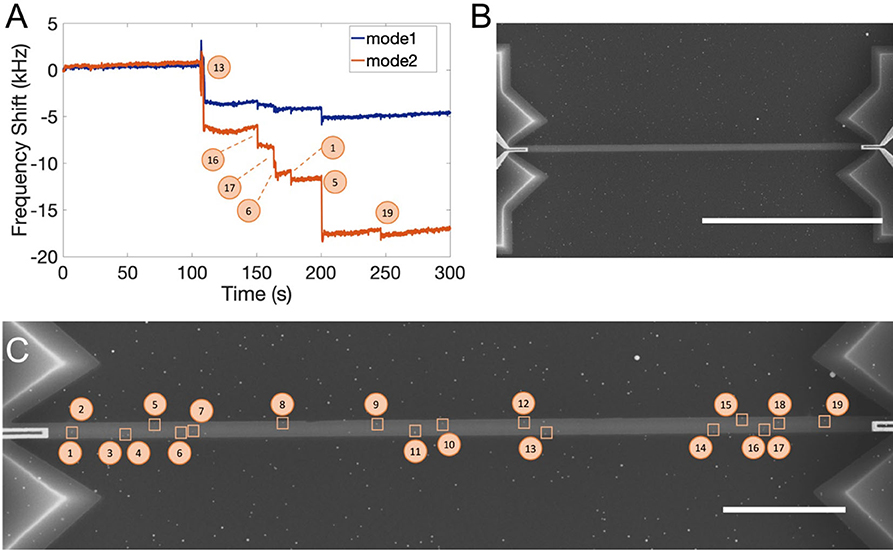
Figure 2. GNP adsorption events tracked by PLL. (A) Each frequency shift represents an individual event. PLL has ~500 ms time constant. The numbers indicate the particles that are later identified under SEM in part C. (B) SEM image of NEMS resonator after nanoparticle adsorption. The scale bar is 10 μm. (C) Collage of three high-resolution SEM images for recording the positions of the nanoparticles. Particles with ambiguous matching between the NEMS and SEM measurements were excluded from the analysis to reduce uncertainty. The scale bar is 3 μm.
The comparison between the position values obtained through SEM imaging and frequency shift measurements are shown in Figures 3, 4 for two resonators with 15 and 20 μm lengths, respectively. For each device, different mode shapes for NEMS are used in the analysis. Two of the mode shapes correspond to the two ideal cases, the Euler mode shape for the pure bending solution and the sinusoidal mode shape for the pure string under tension solution (Supplementary Information). Of course, the actual NEMS device has elastic contributions from both mechanisms. To calculate the mode shape in this case, we first use the resonance frequency values for the first two modes and FEM analysis to determine the intrinsic stress on the structure (Table 1). The stiffness of the beam increases under the existence of intrinsic stress and this increases the resonance frequencies. An axial stress value of 816 MPa is obtained by fitting the resonance frequencies of the first two modes: this stress value agrees with the range of values provided by the supplier of the wafer. Using the stress value, two additional mode shapes are generated (Table 2 and Supplementary Information). The first one uses the combined analytical model of beam bending under tension (Bokaian, 1990) to generate mode shapes in a MATLAB environment. Finally, mode shapes are directly extracted from the FEM solver using 1001 grid points along the top surface and used to reverse calculate the positions using the two-mode theory. The performance of the two-mode theory with respect to these four different mode shapes is shown in Figure 5 and tabulated in Tables 3, 4 for the 15 and 20 μm devices, respectively. We quantify the error by:
where we define xSEM to be the measured position under the SEM (and normalized with respect to the length of the NEMS), and xNEMS for the position obtained by converting NEMS frequency shift results into position values by using the corresponding beam model (Euler-Bernoulli, string under tension, beam under tension or mode shapes obtained by FEM).
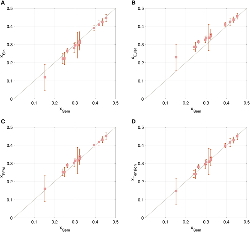
Figure 3. Comparison of position values obtained by SEM characterization (x-axis) along the normalized beam length, and those obtained by NEMS (y-axis) using various mode shapes, (A) sinusoidal, (B) Euler-Bernoulli beam theory, (C) FEM simulation, and (D) the analytical solution with tension term. The data shown correspond to the 15 μm device.
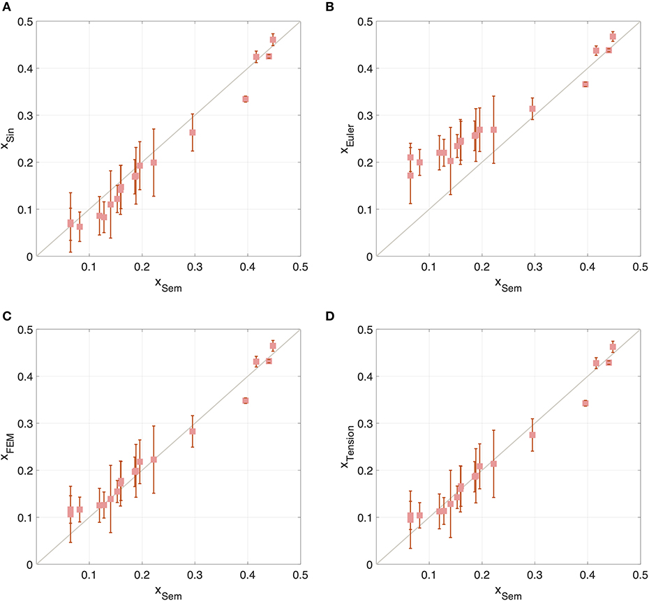
Figure 4. Comparison of position values obtained by SEM characterization (x-axis) along the normalized beam length, and those obtained by NEMS (y-axis) using various mode shapes, (A) sinusoidal, (B) Euler-Bernoulli beam theory, (C) FEM simulation, and (D) the analytical solution with tension term. The data shown here correspond to the 20 μm device.
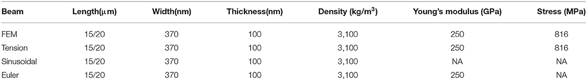
Table 2. Parameters used in the analytical models and FEM simulations.
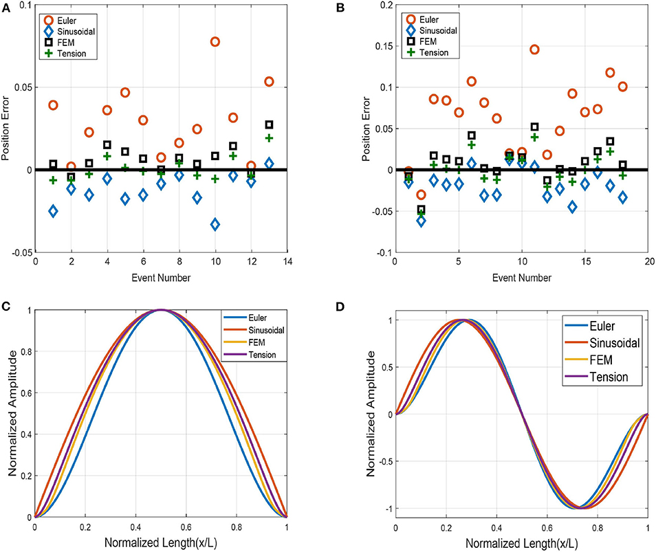
Figure 5. Position errors of different mode shapes according to positions of particles marked in SEM imaging of (A) the 15 μm beam, and (B) the 20 μm beam for different beam models. (C) Mode shapes of the 1st Vibration Mode (D) Mode shapes of the 2nd Vibration Mode.
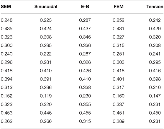
Table 3. Position values for 15 μm beam.
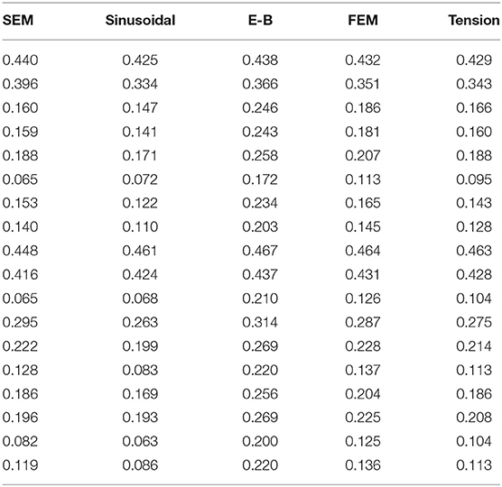
Table 4. Position values for 20 μm beam.
Mass values of the particles obtained by using analytical solution with tension term are shown in Tables 3, 4. The particles that are close to the clamping are excluded since the uncertainty in determining the mass is large in this region. The rms error, for each mode shape is tabulated in Table 5, where N denotes the number of error values.
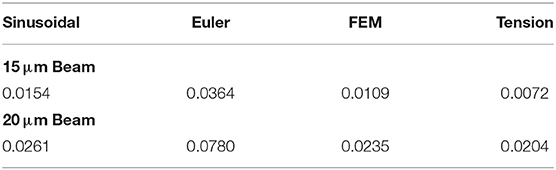
Table 5. Rms of errors.
The beam is assumed to have a uniform cross-section, ignoring any fabrication imperfections. Position errors are calculated after matching the SEM positions of the particles with position values obtained from each mode shape. By observing the error trends in Figure 5, it is evident that a solution based on pure Euler-Bernoulli (E-B) theory deviates the most from SEM position values presumably due to unaccounted axial stress with this theory. By examining the rms errors in Table 5, we see that the remaining three mode shapes yield similar results—the combined analytical mode shape result seems to offer the best performance. This raises a question: how is it that the combined model yields better predictions than the FEM model? The reason is interpreted to be due to the number of grid points in the simulation (1001) along the longitudinal dimension which is a typical value for NEMS simulations. In any case, the results indicate that Euler-Bernoulli mode shapes are not sufficient to accurately determine the position of the analytes when there is significant stress on the beam.
Another important trend in Figures 3, 4 is that the two-mode theory works much better near the center of the beam and the accuracy near the center is relatively insensitive to the model selected. This trend is expected due to the increased sensitivity away from the clamps, especially for the first mode. As it is seen in Figure 5, mode shapes of FEM model and analytical solution with tension term show similar trend and sinusoidal mode shape is even closer to them than the Euler-Bernoulli mode shape. It demonstrates that the sinusoidal model can serve as a starting model for position sensing, and that the tension or FEM models are more accurate when the particles are landing away from the center of the beam.
Both the stress and the bending rigidity play an important role in the mode shapes of the NEMS devices. On the other hand, the sinusoidal and the Euler-Bernoulli mode shapes are merely the two limiting cases for the beam model: zero bending rigidity and zero stress, respectively. Since the actual mode shapes are in between these two limiting factors, the predictions of the sinusoidal and EB mode shapes err in opposite directions. The prediction error of the sinusoidal and EB mode shapes are the largest for particles landing near the edges and they are indicative of the distinct boundary conditions imposed by the underlying dynamics assumed for each case: pinned-pinned boundary conditions for the sinusoidal, and clamped-clamped boundary conditions for the EB mode shapes. Near the center of the beam, the effects of the boundary conditions are washed out, and the beam equations of different models are sufficiently similar to each other to give rise to a convergence of mode shapes and predictions of particle positions.
The function which is defined as the ratio of the first mode shape to the second mode shape is the identifying factor to determine the landing position (Hanay et al., 2012). The models used to calculate the mode shapes show slightly different results from each other, therefore results in different ratios. For example, the slope of the first two mode shapes vanishes on the clamped edges in the Euler-Bernoulli model while it has a finite value in the string-under-tension model. In reality, the mode shapes are expected to lie between these two extremes, therefore the ratio of the mode shapes will have a value in between. The particular geometry of the mode shapes in each model will determine whether the model will under-estimate or over-estimate the position.
Any improvement in the determination of the position of a particle is expected to increase the accuracy of the mass measurement of that particle. This statement can be understood by considering the equation that relates the mass and position of a point particle written for the fundamental mode as (Hanay et al., 2012):
where Δm is the mass and x is the position of the particle; Meff is the effective mass, Δf is the frequency shift, f0 is the resonance frequency, and ϕ(x) is the mode shape of the fundamental mode [normalized such that max(ϕ(x)) = 1]. Since there is a direct correspondence between the mass and the position of the particle, one can then use standard techniques for error propagation to relate the uncertainty in one parameter to the other (Hanay et al., 2012).
The experimentally determined mean diameter of nanoparticles is 36.5 nm and the mean mass value is 297 MDa which indicates a significant amount of aggregation of nanoparticles. Nevertheless, the position analysis conducted here does not directly depend on the specific mass value of the analytes, since the position value depends on the ratio of the frequency shift in the second mode to the frequency shift in the first mode—and this ratio is constant to first order for particles of different mass but the same position. It would have been interesting to compare the mass spectrum of nanoparticles calculated by using the position values of different models. However, this comparison cannot be properly made for the GNP sample used, because of the high dispersion of the molecular weight (~%40) and the aggregation of nanoparticles during the sample preparation.
We investigated the position sensing performance of NEMS sensors by calculating the position values for multiple GNPs using different models of beam elasticity. Independent SEM characterization of each adsorption was used to validate GNP positions. The analysis suggests tension term should be included to the beam theory for the mode shape calculations especially for structures under high tensile stress. Moreover, the performance of mode shapes obtained by either a simple sinusoidal approximation or through FEM analysis resulted in acceptable performance levels for the determination of particle positions. Meticulous measurements of device dimensions after fabrication under the SEM followed by FEM modeling is one possible approach to increase position resolution. Keeping a record of particles as they land on the sensor and using this information to update the mode shape using perturbation theory (Yüksel and Hanay, 2017) can also alleviate uncertainties due to mode shape. The accuracy of mode shapes is crucial in position-dependent sensing applications. Since nanomechanical motion occurs at high frequencies and on a miniscule area, it is challenging to image the actual mode shape. However, using SEM and averaging of the resonant motion (Ghatkesar et al., 2007), or imaging post-buckling curves can be used to capture the effective mode shape (Ahmad et al., 2011; Erbil et al., 2020). The use of correct mode shapes increases the position sensing performance of nanomechanical sensors which can then enable the delivery, positioning, and control of nanoparticles within the NEMS platform.
The datasets generated for this study are available on request to the corresponding author.
MH, EO, and MY conceived the idea. EO, MY, and UH designed the experimental setup. CY, AA, AY, and EO fabricated the devices. EO and MY acquired the data and performed the analyses. All authors contributed in writing the manuscript.
This work was funded by the Scientific and Technological Research Council of Turkey (TÜBITAK), Grant No. EEEAG-115E230.
The authors declare that the research was conducted in the absence of any commercial or financial relationships that could be construed as a potential conflict of interest.
MH acknowledges the Science Academy, Turkey (Bilim Akademisi) and the Turkey Academy of Sciences (TÜBA) for support.
The Supplementary Material for this article can be found online at: https://www.frontiersin.org/articles/10.3389/fmech.2020.00037/full#supplementary-material
Ahmad, M. R., Nakajima, M., Kojima, S., Homma, M., and Fukuda, T. (2011). Buckling nanoneedle for characterizing single cells mechanics inside environmental SEM. IEEE Trans. Nanotechnol. 10, 226–236. doi: 10.1109/TNANO.2009.2036997
Ari, A. B., Karakan, M. Ç., Yanik, C., Kaya, I. I., and Hanay, M. S. (2018). Intermodal coupling as a probe for detecting nanomechanical modes. Phys. Rev. Appl. 9:034024. doi: 10.1103/PhysRevApplied.9.034024
Bargatin, I., Kozinsky, I., and Roukes, M. L. (2007). Efficient electrothermal actuation of multiple modes of high-frequency nanoelectromechanical resonators. Appl. Phys. Lett. 90, 093116. doi: 10.1063/1.2709620
Beardslee, L. A., Addous, A. M., Heinrich, S., Josse, F., Dufour, I., and Brand, O. (2010). Thermal excitation and piezoresistive detection of cantilever in-plane resonance modes for sensing applications. J. Microelectromech. Syst. 19, 1015–1017. doi: 10.1109/JMEMS.2010.2052093
Biswas, T., Xu, J., Miriyala, N., Doolin, C., Thundat, T., Davis, J., et al. (2015). Time-resolved mass sensing of a molecular adsorbate nonuniformly distributed along a nanomechnical string. Phys. Rev. Appl. 3:064002. doi: 10.1103/PhysRevApplied.3.064002
Bokaian, A. (1990). Natural frequencies of beams under tensile axial loads. J. Sound Vib. 142, 481–498. doi: 10.1016/0022-460X(90)90663-K
Bouchaala, A., Nayfeh, A. H., Jaber, N., and Younis, M. I. (2016). Mass and position determination in MEMS mass sensors: a theoretical and an experimental investigation. J. Micromech. Microeng. 26:105009. doi: 10.1088/0960-1317/26/10/105009
Chaste, J., Eichler, A., Moser, J., Ceballos, G., Rurali, R., and Bachtold, A. (2012). A nanomechanical mass sensor with yoctogram resolution. Nat. Nanotechnol. 7:301. doi: 10.1038/nnano.2012.42
Chiu, H.-Y., Hung, P., Postma, H. W. C., and Bockrath, M. (2008). Atomic-scale mass sensing using carbon nanotube resonators. Nano Lett. 8, 4342–4346. doi: 10.1021/nl802181c
Dilena, M., Dell'oste, M. F., Fernández-Sáez, J., Morassi, A., and Zaera, R. (2020). Hearing distributed mass in nanobeam resonators. Int. J. Solids Struct. 183–194, 568–592. doi: 10.1016/j.ijsolstr.2020.02.025
Dohn, S., Sandberg, R., Svendsen, W., and Boisen, A. (2005). Enhanced functionality of cantilever based mass sensors using higher modes. Appl. Phys. Lett. 86:233501. doi: 10.1063/1.1948521
Dohn, S., Schmid, S., Amiot, F., and Boisen, A. (2010). Position and mass determination of multiple particles using cantilever based mass sensors. Appl. Phys. Lett. 97:044103. doi: 10.1063/1.3473761
Dohn, S., Svendsen, W., Boisen, A., and Hansen, O. (2007). Mass and position determination of attached particles on cantilever based mass sensors. Rev. Sci. Instrum. 78:103303. doi: 10.1063/1.2804074
Ekinci, K. L., Huang, X. M. H., and Roukes, M. L. (2004a). Ultrasensitive nanoelectromechanical mass detection. Appl. Phys. Lett. 84, 4469–4471. doi: 10.1063/1.1755417
Ekinci, K. L., Yang, Y. T., and Roukes, M. L. (2004b). Ultimate limits to inertial mass sensing based upon nanoelectromechanical systems. J. Appl. Phys. 95, 2682–2689. doi: 10.1063/1.1642738
Erbil, S., Hatipoglu, U., Yanik, C., Ghavami, M., Ari, A., Yuksel, M., et al. (2020). Full electrostatic control of nanomechanical buckling. Phys. Rev. Lett. 124:046101. doi: 10.1103/PhysRevLett.124.046101
Ghatkesar, M. K., Barwich, V., Braun, T., Ramseyer, J.-P., Gerber, C., Hegner, M., et al. (2007). Higher modes of vibration increase mass sensitivity in nanomechanical microcantilevers. Nanotechnology 18:445502. doi: 10.1088/0957-4484/18/44/445502
Hanay, M. S., Kelber, S., Naik, A. K., Chi, D., Hentz, S., Bullard, E. C., et al. (2012). Single-protein nanomechanical mass spectrometry in real time. Nat. Nanotechnol. 7, 602–608. doi: 10.1038/nnano.2012.119
Hanay, M. S., Kelber, S. I., O'connell, C. D., Mulvaney, P., Sader, J. E., and Roukes, M. L. (2015). Inertial imaging with nanomechanical systems. Nat. Nanotechnol. 10, 339–344. doi: 10.1038/nnano.2015.32
Heinrich, S. M., and Dufour, I. (2015). Toward higher-order mass detection: Influence of an adsorbate's rotational inertia and eccentricity on the resonant response of a Bernoulli-Euler cantilever beam. Sensors 15, 29209–29232. doi: 10.3390/s151129209
Ilic, B., Craighead, H. G., Krylov, S., Senaratne, W., Ober, C., and Neuzil, P. (2004). Attogram detection using nanoelectromechanical oscillators. J. Appl. Phys. 95, 3694–3703. doi: 10.1063/1.1650542
Jensen, K., Kim, K., and Zettl, A. (2008). An atomic-resolution nanomechanical mass sensor. Nat. Nanotechnol. 3, 533. doi: 10.1038/nnano.2008.200
Jia, H., and Feng, P. X.-L. (2019). Very high-frequency silicon carbide microdisk resonators with multimode responses in water for particle sensing. J. Microelectromech. Syst. 28, 941–953. doi: 10.1109/JMEMS.2019.2920329
Kelleci, M., Aydogmus, H., Aslanbas, L., Erbil, S. O., and Hanay, M. S. (2018). Towards microwave imaging of cells. Lab Chip 18, 463–472. doi: 10.1039/C7LC01251A
Lassagne, B., Garcia-Sanchez, D., Aguasca, A., and Bachtold, A. (2008). Ultrasensitive mass sensing with a nanotube electromechanical resonator. Nano Lett. 8, 3735–3738. doi: 10.1021/nl801982v
Lobontiu, N., Ilic, B., Garcia, E., Reissman, T., and Craighead, H. (2006). Modeling of nanofabricated paddle bridges for resonant mass sensing. Rev. Sci. Instrum. 77:073301. doi: 10.1063/1.2221560
Malvar, O., Ruz, J., Kosaka, P. M., Domínguez, C. M., Gil-Santos, E., Calleja, M., et al. (2016). Mass and stiffness spectrometry of nanoparticles and whole intact bacteria by multimode nanomechanical resonators. Nat. Commun. 7:13452. doi: 10.1038/ncomms13452
Martín-Pérez, A., Ramos, D., Gil-Santos, E., García-López, S., Yubero, M. L., Kosaka, P. M., et al. (2019). Mechano-optical analysis of single cells with transparent microcapillary resonators. ACS Sens. 4, 3325–3332. doi: 10.1021/acssensors.9b02038
Naik, A. K., Hanay, M. S., Hiebert, W. K., Feng, X. L., and Roukes, M. L. (2009). Towards single-molecule nanomechanical mass spectrometry. Nat. Nanotechnol. 4, 445–450. doi: 10.1038/nnano.2009.152
Olcum, S., Cermak, N., Wasserman, S. C., and Manalis, S. R. (2015). High-speed multiple-mode mass-sensing resolves dynamic nanoscale mass distributions. Nat. Commun. 6:7070. doi: 10.1038/ncomms8070
Park, K., Millet, L. J., Kim, N., Li, H., Jin, X., Popescu, G., et al. (2010). Measurement of adherent cell mass and growth. Proc. Natl Acad. Sci. U.S.A. 107, 20691–20696. doi: 10.1073/pnas.1011365107
Ramos, D., Calleja, M., Mertens, J., Zaballos, Á., and Tamayo, J. (2007). Measurement of the mass and rigidity of adsorbates on a microcantilever sensor. Sensors 7, 1834–1845. doi: 10.3390/s7091834
Ramos, D., Tamayo, J., Mertens, J., Calleja, M., and Zaballos, A. (2006). Origin of the response of nanomechanical resonators to bacteria adsorption. J. Appl. Phys. 100:106105. doi: 10.1063/1.2370507
Sader, J. E., Hanay, M. S., Neumann, A. P., and Roukes, M. L. (2018). Mass spectrometry using nanomechanical systems: beyond the point-mass approximation. Nano Lett. 18, 1608–1614. doi: 10.1021/acs.nanolett.7b04301
Sansa, M., Defoort, M., Brenac, A., Hermouet, M., Banniard, L., Fafin, A., et al. (2020). Optomechanical mass spectrometry. arXiv preprint arXiv:2004.06683.
Stachiv, I., Fedorchenko, A., and Chen, Y.-L. (2012). Mass detection by means of the vibrating nanomechanical resonators. Appl. Phys. Lett. 100:093110. doi: 10.1063/1.3691195
Tamayo, J., Ramos, D., Mertens, J., and Calleja, M. (2006). Effect of the adsorbate stiffness on the resonance response of microcantilever sensors. Appl. Phys. Lett. 89:224104. doi: 10.1063/1.2388925
Yang, Y. T., Callegari, C., Feng, X. L., Ekinci, K. L., and Roukes, M. L. (2006). Zeptogram-scale nanomechanical mass sensing. Nano Lett. 6, 583–586. doi: 10.1021/nl052134m
Yüksel, M., and Hanay, M. S. (2017). Mode-shape perturbation induced by analyte adsorption in nanomechanical sensors. arXiv 1709:01496.
Keywords: NEMS, MEMS, position sensing, nanomanipulation, inertial imaging
Citation: Orhan E, Yuksel M, Ari AB, Yanik C, Hatipoglu U, Yağci AM and Hanay MS (2020) Performance of Nano-Electromechanical Systems as Nanoparticle Position Sensors. Front. Mech. Eng. 6:37. doi: 10.3389/fmech.2020.00037
Received: 14 February 2020; Accepted: 12 May 2020;
Published: 10 June 2020.
Edited by:
Silvan Schmid, Vienna University of Technology, AustriaReviewed by:
Stephen M. Heinrich, Marquette University, United StatesCopyright © 2020 Orhan, Yuksel, Ari, Yanik, Hatipoglu, Yağci and Hanay. This is an open-access article distributed under the terms of the Creative Commons Attribution License (CC BY). The use, distribution or reproduction in other forums is permitted, provided the original author(s) and the copyright owner(s) are credited and that the original publication in this journal is cited, in accordance with accepted academic practice. No use, distribution or reproduction is permitted which does not comply with these terms.
*Correspondence: M. Selim Hanay, c2VsaW1oYW5heUBiaWxrZW50LmVkdS50cg==
Disclaimer: All claims expressed in this article are solely those of the authors and do not necessarily represent those of their affiliated organizations, or those of the publisher, the editors and the reviewers. Any product that may be evaluated in this article or claim that may be made by its manufacturer is not guaranteed or endorsed by the publisher.
Research integrity at Frontiers
Learn more about the work of our research integrity team to safeguard the quality of each article we publish.