
94% of researchers rate our articles as excellent or good
Learn more about the work of our research integrity team to safeguard the quality of each article we publish.
Find out more
ORIGINAL RESEARCH article
Front. Mech. Eng., 05 June 2020
Sec. Tribology
Volume 6 - 2020 | https://doi.org/10.3389/fmech.2020.00030
This article is part of the Research TopicContact mechanics perspective of tribologyView all 37 articles
This paper is concerned with possible applications of semi-analytical methods of frictional contact mechanics. The semi-analytical solutions, such as the Method of Memory Diagrams, enable the load-displacement relationship for contact of two axisymmetric bodies with friction to be written as an analytical expression with parameters calculated via a numerical procedure. As a result, a complex history-dependent solution is obtained for an arbitrary loading history in a computationally efficient way. This fact allows one to calculate hysteretic responses to extremely complex loading histories, such as random vibrations. Another case when complex loading histories appear is in a harmonic excitation of a dynamic contact system in which inertia is taken into account. Both examples are considered here. The random excitation case can be used as a basis for modeling for wear in frictional contacts while the second one may be extended to describe coupled dynamic contact systems, stick-slip phenomena, or friction-induced instabilities.
This paper concerns the use of one semi-analytical method of frictional contact mechanics. The term “frictional contact mechanics” can comprise a large variety of problems. Here it is used in the following sense: (i) friction is a phenomenon that arises due to tangential interactions of bodies in contact, and (ii) frictional interaction is governed by the classical one-term law of friction (Coulomb friction law) originating in the works of Amontons. The second aspect is discussed in more detail from a historical point of view by Desplanques (2015) or Borodich and Savencu (2017). The first feature is essential as friction can also appear in a purely compressional loading case [see e.g., Borodich and Keer (2004)]. In any situation, friction results in a hysteretic response which depends not only on instantaneous values of drive parameters, but also on their history.
Further, methods belonging to the semi-analytical class (Dobry et al., 1991; Jäger, 2005; Aleshin et al., 2015, 2019; Popov and Heß, 2015; Popov et al., 2019) allow one to obtain a frictional contact response as an analytical solution that depends on parameters determined by an algorithm. For the price of accepting a certain number of simplifications (such as axisymmetric contact geometry, neglect for elastic dissimilarity of the bodies, and approximate fulfillment of the Coulomb friction law) extremely rapid and efficient calculation techniques are developed. The high computational performance makes these methods suitable for implementation in complex loading histories (e.g., random vibrations or acoustic waves).
In the fourth of the cited methods, the Method of Memory Diagrams (MMD), the contact characteristics such as local and global displacements, stress distributions, and contact loads are calculated via an internal memory fiction or diagram constantly updated following the excitation protocol. The memory function is defined on an adaptive grid whose points are dynamically adjusted in accordance to the applied excitation. In addition to the mechanical response, the friction-induced energy dissipation is analytically described. The MMD is sketched in section method of the memory diagrams of this paper preceded by section Hertz-Mindlin mechanics in which some basic solutions of contact mechanics are recalled.
In sections friction-induced energy dissipation in spherical contacts excited by random vibrations and section contact system with a finite mass dynamically excited by external forces, two examples of MMD applications are considered. The first example is concerned with a prestressed axisymmetric contact excited by random vibrations that represent random displacement time histories having fractal properties. In such a system, the mechanical and energetic responses depend on a very restrained number of parameters, such as the fractal dimension, the normal, and tangential displacement amplitudes normalized on the prestress value, and the ratio of the maximum and minimum frequencies of the excitation spectrum. In particular, it can be shown that at high amplitudes most of the energy is dissipated near the contact center while for low amplitudes the energy dissipation zone represents an annulus located inside of the mean contact circle. These results can be of use for determining parts of mechanical systems in which wear or thermal fatigue is most likely to appear.
The second example is a dynamic (i.e., having a mass and inertia) frictional contact system excited by a harmonic tangential force. Even the simplest case of a single contact with constant compression demonstrates rich dynamic effects. In particular, various time scales can appear under various combinations of a system's parameters. The responses can be categorized into several classes characterized by growing or complex oscillatory behavior.
In another case considered elsewhere (Aleshin et al., 2019), a solid material with a frictional crack is insonified by ultrasound. It can be shown that rough faces of cracks behave approximately as effective axisymmetric bodies (Jäger, 1995; Ciavarella, 1998) having the same normal reaction, thus suggesting the use of the MMD. The MMD-based contact model has been integrated with a finite-element environment (COMSOL). Doing so, a simulation tool called MMD-FEM has been elaborated for modeling acoustic responses of damaged materials, including nonlinear acoustic effects that are usually applied in modern nondestructive testing technologies.
Similarly to other semi-analytical methods in contact mechanics, the MMD can be regarded as a direct generalization of the classical Cattaneo-Mindlin (Cattaneo, 1938; Mindlin and Deresiewicz, 1953) solution developed for elastic spheres in contact loaded by a subsequent application of constant normal and tangential forces. As it was shown, the contact zone consists of stick and slip areas that represent a central circle, and outer annulus, respectively. In the stick zone, no relative tangential displacement between close points belonging to the opposite surfaces is possible. In the slip zone, the shear stress τ equals the normal stress σ times the friction coefficient μ, in accordance to the Coulomb friction law. At the same time, in that zone, the relative tangential displacement is a nonzero vector that must be directed as the local shear stress vector. The latter condition can be called the orientation aspect or property of the Coulomb friction law.
The most compact derivation (Jäger, 1995) is based on a superposition of the Bossiness solutions for rigid punches straining an elastic half-space in both normal and tangential senses. The smallest punch in the superposition coincides with the stick circle radius that guarantees the no-slip condition in the stick zone, and the largest one is the size of the contact zone itself. By a proper choice of “strengths” of the punches in the normal and tangential directions it is possible to satisfy the Coulomb condition τ = μ σ. However, the orientational property is satisfied only approximately. The issue is that for punches applied in the x-direction parallel to the half-space surface, the local vectors are all directed along the same x-axis, while the tangential displacement vector has a non-zero in-plane y-component [Equation (28c) in Jäger (1995)]. Another simplification is related to the neglect of the second term in the second line of Equation (28b) in the cited paper. In addition, the Catteneo-Mindlin approximation disregards dissimilarity phenomena (Munisamy et al., 1994) which, if present, can produce local tangential displacement for purely normal compression, since the Poisson effect can be of different magnitudes for non-equal spheres of different materials. However, despite some assumptions in the analysis, the Cattaneo-Mindlin solution remains a good approximation of frictional contact interaction of axisymmetric bodies largely used since 1950's. For equal bodies with the elastic constants E and ν having the contact geometry as in Figure 1 (contact forces N and T, and displacements a and b, contact zone radius c, and stick zone radius s) the solution has the following form:
with E* and θ defined as
In this solution, all geometric features of the contact system are taken into account through the dependences N = N(c) and a = a(c) in Equations (1, 2). The result can be rewritten using these functions as
where in the last terms of each equation the argument of functions N(·) and a(·) is the radius of the stick zone s. The result Equation (7) is frequently referred to as the reduced elastic friction principle (Jäger, 2005). The principle Equation (7), in contrast to Equations (1–4), is valid for any axisymmetric contact geometry, not necessarily spherical.
The MMD (Aleshin et al., 2015, 2019) develops the principle described in the previous section by applying it to more general loading histories which consist in arbitrarily changing oblique compressions in 2D or in 3D (the former means that the normal and tangential forces stay in one plane). The calculation is organized with the use of an auxiliary inter function D(ρ), called a memory diagram, that encodes all memory information in the frictional system. In 2D, the solution reads
In the previously considered “simple loading case” (Figure 2A) [i.e., when the tangential action is added after application of constant normal compression], the memory diagram has a simple rectangular shape that corresponds to the classical result Equation (7) after calculation of the integral in Equation (8).
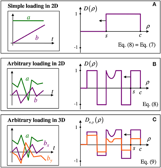
Figure 2. Illustration for the MMD: loading histories at the left and memory diagrams at the right, for the simple loading (A), arbitrary loading in 2D (B), and in 3D (C). Here, s<ρ<c is slip annulus, see also Figure 1.
An arbitrary loading history in 2D corresponds to a more complex shape of the memory diagram that can consist of positive and negative horizontal elements as well as from curvilinear sections (Figure 2B). The algorithm (Aleshin et al., 2015) keeps track of the evolution of the loading parameters and updates the diagram shape accordingly, in order to keep the balance equation (8). This formula does not require any additional assumptions in comparison to the reduced elastic friction principle Equation (7). Limitations related to this principle are discussed by Jäger (2005) and also mentioned in the paper (Aleshin et al., 2015) where the MMD in described in more detail.
If the loading parameters are allowed to arbitrarily vary in 3D, the system can be described via a vector counterpart of Equation (8) which reads,
However, the analysis (Aleshin and Bou Matar, 2016) neglects the orientational aspect of the Coulomb friction law and therefore should be considered as an approximation.
Equations (8) or (9), together with the algorithm governing the memory diagram evolution, provide the possibility to calculate the hysteretic tangential load-displacement relationship through the known normal load-displacement relationship given by N = N(c) and a = a(c). The method works when the forces are considered as arguments and displacements are unknown or vice versa. At the same time, it is important to emphasize that the MMD introduced above is only valid for partial slip (i.e., when some stick zone remains around ρ = 0. If |T| reaches μN or |b| reaches θμa, the stick zone disappears). The force-driven system excited by a tangential force exceeding μN will experience accelerated movement which violates the current quasi-static character of description and generally complicates the problem. Fortunately, in the case where the system is driven by displacements, there exists a simple way to construct a quasi-static force-displacement relationship valid in all situations which may be encountered: partial slip, total sliding, and contact loss.
To do so, we introduce two displacement components of the total displacement
as illustrated in Figure 3; reflects deformation of one of the contacting bodies due to shearing while is a tangential shift between the contact centers that develops due to total sliding. Since we already consider small displacements in comparison to all geometric features, the effects of the slight drop of the upper body because of the tangential mismatch or contact plane rotation are neglected.

Figure 3. Partial tangential displacements due to shearing of the bodies and due to the shift between contact centers.
For the 2D case, the algorithm that provides the unknown tangential force is shown in Figure 4. When the contact is lost, there is no contact interaction, and the bodies are unstrained (i.e., N = T = 0). When total sliding takes place, T = ±μN with the sign depending on the sliding direction. Finally, for partial slip the MMD algorithm has to be applied, which is symbolically expressed as . In each case, one of the components, b0 or , is known directly, and the other one is immediately found since their sum equals the known argument. Numerically, the algorithm is applied to small increments Δb and Δa and updates previous values with small changes calculated at the current step which become previous values at the next step, etc.
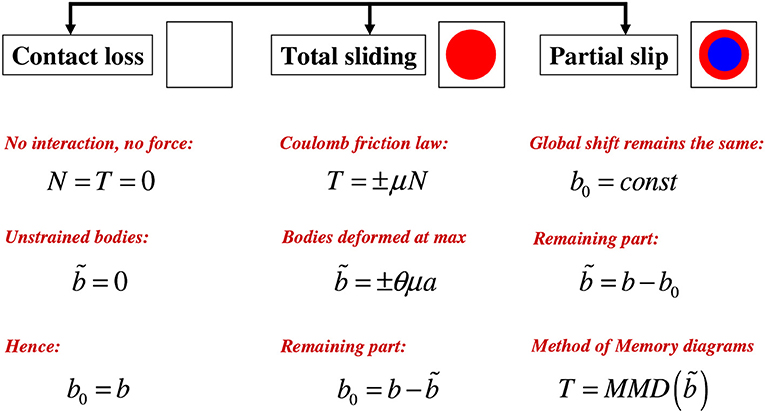
Figure 4. Three contact states (contact loss, total sliding, and partial slip) and the corresponding solutions for T obtained via repartition for loading in 2D (normal and tangential displacements always stay in one plane).
In the 3D loading case, tangential displacement b, its components b0 and , and force T in Figure 4 become vectors. In addition, the formulas for the total sliding case have to be further modified since sliding does not occur in the positive or negative direction as in 2D, but in a direction given by the unit vector where is an infinitesimal slip vector. These vectors are also collinear with the tangential force, , since slip is caused by (orientational aspect of the Coulomb friction law). From the previous considerations we also know that [assume s = 0 in Figure 2A or in Equation (7)]. Then the repartition Equation (10) takes the form
in which is the known component at the previous step, and the two last vectors are collinear. Finally, is obtained as a unit vector collinear to
and then . The infinitesimal slip vector becomes equal which means that all components of the repartition Equation (11) at the current step are determined.
For brevity, the term MMD comprises the extension to the contact loss and total sliding cases (Figure 4), not only thee partial slip situation in Equations (8) or (9). The formulation shown in Figures 2, 4 illustrated the efficiency of the method. Indeed, instead of considering detailed evolving distributions of local stresses and displacements, it is enough to introduce and update one inner memory function (two functions in 3D). Moreover, the function frequently contains constant segments thus the memorization of only the beginning and the end of each segment and not all intermediate points. The MMD algorithm is based on an adaptive grid whose points are created and deleted following the loading protocol instead of being predefined at fixed positions. As a result, the method is especially suitable to complex loading protocols such as random or acoustical excitation. At the same time, the contact geometry should remain relatively simple in order to be imitated by axisymmetric shapes.
In the next sections it is shown how the MMD solution to the contact problem can be used for an efficient description of frictional contacts excited by complex loading histories.
The semi-analytic MMD formulation of the solution to the contact problem makes it possible to derive an expression (Truyaert et al., 2019) for the friction-induced energy dissipation in the incremental form valid for all three contact states, regardless the shape of the memory diagram:
Here the normal load-displacement relationship N(a) derived [e.g., in (Jäger, 1995)] for any axisymmetric contact geometry is used. Moreover, the same considerations (Truyaert et al., 2019) enable one to write the surface density of the energy loss defined by
in the form
in which the explicit knowledge of the normal stress distribution σ(ρ) is required.
To reveal general tendencies in the frictional dissipation behavior, it is meaningful to consider a frictional system with a very restrained number of parameters. Aleshin and Papangelo (2020) suggested the use of a prestressed contact of two spheres excited by random normal and tangential displacements of equal rms having fractal time dependences in a certain frequency range. By the proper choice of normalization, it is possible to limit the number of parameters to three: rms amplitudes ar = br normalized on the prestress displacement, fractal dimension D, and higher cut-off frequency fH normalized on the lower one. For a fractal curve, the power spectral density is given by
where D belongs to the interval 1<D<2. It is straightforward to show (Aleshin and Papangelo, 2020) that extending the range for D to 0<D<1 and −1<D<0 in Equation (15) will lead to fractal behavior for the velocity and acceleration time dependences. The fractal shape for S(f) is selected since fractality of a random curve is related to (i) the Gaussian distribution of the random value which is in turn a consequence of a large number of factors that impact that value, as well as (ii) the power-law frequency dependence for S(f) which means the absence of a characteristic frequency in the spectrum and reduces the number of free parameters by one. Certainly, in a real particular contact system, the statistical properties of the random excitation can differ.
As expected, average power P dissipated during a sizable interval of dimensionless time normalized on the inverse lower cut-off frequency is approximately constant (Figure 5). In our simulation, the number of time points equals 219 = 524288 and is high enough to neglect differences in two particular realizations which accumulate a lot of random features during a long observation time of 5,000 normalized units. The stiffness of curves in Figure 5 having the sense of the dissipated power depends on all parameters of the problem. Power P growths with increasing amplitudes ar = br, with increasing frequency range fH, and with increasing D. The last two effects are due to the fact that higher frequencies added by extending the range or amplifying existing HF components additionally generate loading-unloading cycles. Despite their small amplitude, they are frequent and therefore significantly contribute to the total energy loss.
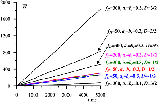
Figure 5. Dissipated energy W as a function of time for different values of problems' parameters. The curves are approximately linear which means that the average dissipated power P is constant.
In Figure 5 each curve is primarily characterized by a single parameter, its slope. More information is contained in the surface density of the dissipated power. To compare surface densities for different values of parameters, we calculate the form-factor Φ(ρ) introduced by the relationship
and normalized in order to have unit integral
for each realization.
Figure 6 shows that form-factors can vary a lot depending on the problem's parameters. First of all, for small (such as 0.1 of the prestress displacement) amplitudes of vibrations, most of the energy is dissipated in a thin annulus located close to the average contact border. For moderate amplitudes, the annulus in which most of the dissipation takes place progresses inward and becomes smeared. Finally, for strong vibrations (of about of 0.8 and more), the maximum dissipation occurs in the contact center (i.e., the dissipation zone becomes circular, as the violet curve in Figure 6 indicates). Frequency content in the spectrum also influences the form-factor, but to a lesser degree. For instance, for low D = 1/2 most of the energy is contained in low frequencies, and increasing the upper frequency limit practically does not change anything (black and orange curves). At the same time, for high D = 3/2, extending the frequency range produces a minor effect (brown and green dashed curves). Generally, enhancing high frequency content shifts the annulus closer to the contact center, acting similarly to an amplitude increase, since higher frequencies make the total traveled path longer.
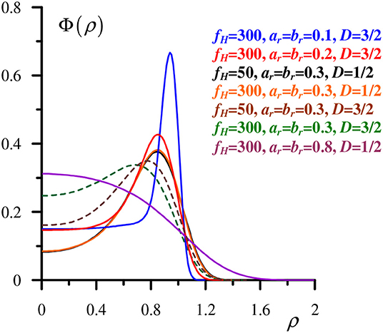
Figure 6. Normalized form-factor of the surface density of the dissipated energy for different values of parameters.
The fact that the form-factors determining the dissipated energy density portray the system's parameters in a finer way than the almost linearly growing total dissipation curves is additionally illustrated in Figure 7. By changing the frequency content of the vibrations spectrum with a simultaneous variation of the vibrations amplitudes, the slopes of two total dissipation curves can be matched. Indeed, in Figure 7A the red and blue curves are close, except that the blue one which represents the response on low-frequency vibrations can locally differ from the average inclination to a greater degree. At the same time, the surface densities of the dissipated energy are essentially distinct (Figure 7B). For small amplitudes, sharp peaks in surface densities curves are typically found. In practice, this means that a profiled joint subject to small but prolonged vibrations will experience wear in a thin annulus close to the contact border. For strong vibrations, wear should start near the contact center.
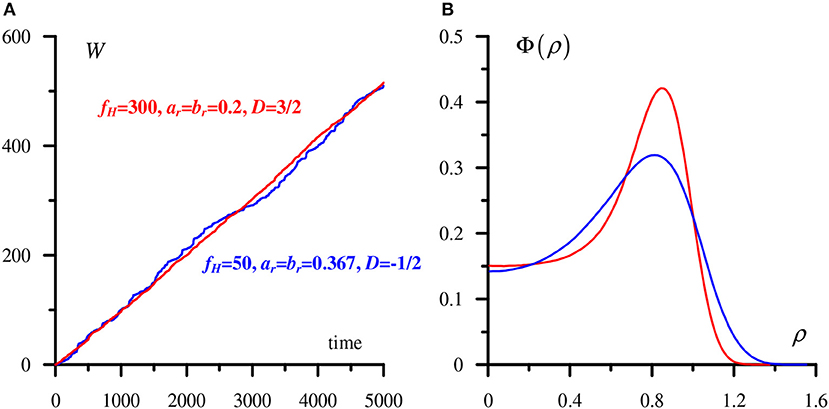
Figure 7. Two total energy dissipation curves can be close once enhanced HF content is compensated for by lowering vibrations amplitude (A), but the surface energy distributions differ significantly (B).
Another example of a problem that can be successfully solved with the use of the MMD, as well as by another method belonging to the semi-analytical class, is the dynamics of a simple system that consists of an axisymmetric body excited by a horizontal tangential force. In the considered case, the body is vertically prestressed on an elastic half-space and has certain mass m. Below it is shown that this geometrically and physically simple system has a rich dynamic behavior arising due to the presence of friction.
The equation of motion for such a body reads:
where b is, as previously, the tangential displacement, Ta is the external tangential force amplitude, f is the harmonic frequency, N0 is the constant vertical compression force, and a0 is the normal displacement caused by that force. Here TMMD is a dimensionless function of a dimensionless tangential displacement; TMMD equals the friction force normalized on μ N0.
In the considered case involving inertia, it is meaningful to distinguish between excitation and loading protocol/history. Here the former one is the sinusoidal term in Equation (17) while the latter one is the argument of TMMD function. We will see that in the considered frictional system the loading protocol becomes rather complex even for a simple excitation signal (sinewave). In the previous quasi-static case (section friction-induced energy dissipation in spherical contacts excited by random vibrations) this difference did not exist, the same way as the equation of motion.
It is convenient to rewrite Equation (17) using dimensionless variables
and get an equation in which all variables and parameters are dimensionless:
Actually, it has only two parameters: m* that characterizes inertial properties for a given frequency, and that corresponds to a relative strength of the external force compared to the friction force. In order to have comparable tangential responses for highly different parameters values, it is appropriate to introduce another dimensionless displacement
When the excitation amplitude is very high, friction is negligible, and the solution has a simple form
that does not depend on any parameters. Here the increasing term ~ t* appears due to the second boundary condition in Equation (17) and may change once this boundary condition alters. For lower friction becomes important, and the system has a whole range of different behaviors illustrated in Figures 8, 9 plotted for heavy (m* = 100, Figure 8) and light (m = 0.01, Figure 9) bodies. The curves represent the tangential displacements (at the left) and the corresponding velocities (at the right) for decreasing drive amplitudes marked by various colors. Solution Equation (21) is plotted in black and is labeled .
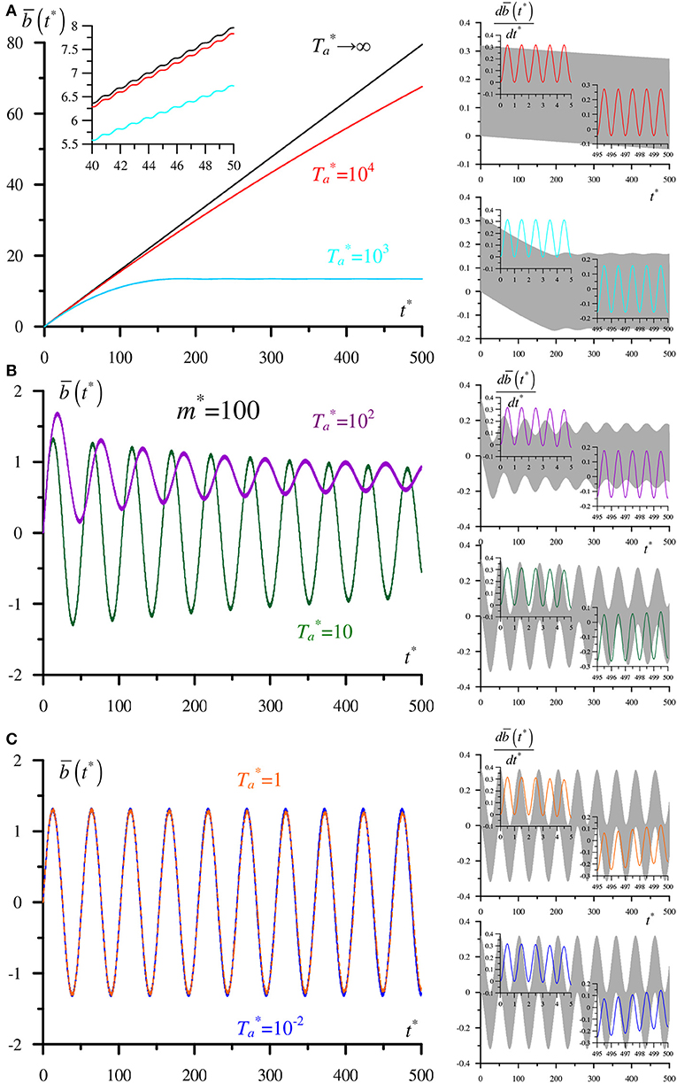
Figure 8. Normalized tangential displacement (at the left) and corresponding velocity (at the right) for different excitation amplitudes for m*=100: (A) → ∞, = 104, and = 103; (B) = 102 and = 10; (C) = 1 and = 10−2.
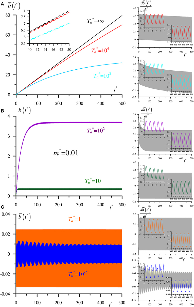
Figure 9. Normalized tangential displacement (at the left) and corresponding velocity (at the right) for different excitation amplitudes for m*= 0.01: (A) → ∞, = 104, and = 103; (B) = 102 and = 10; (C) = 1 and = 10−2.
The principal feature that shows up in Figures 8, 9 is the presence of very different time scales. All curves always oscillate with the period of 1 that corresponds to the driving frequency. Besides the lowest scale of one, characteristic times of about 50 (Figures 8B,C), 20 [(Figure 9C) for , in blue] or another can appear. Generally, observation time of 500 is sufficient to see the character of the dependence. The entire curves for velocities containing 500 oscillations are shown in gray for all drive amplitudes, whereas their fragments at the beginning and at the end of the observation time are plotted in colors corresponding to the particular amplitudes.
For heavy and light bodies excited by strong tangential forces of amplitudes , displacement's behavior represents climbing saturating oscillations [it is expected that the curve for will finally saturate as it does for , only for no saturation is present, Equation (21)]. A progressive decrease in leads to a quicker saturation at a lower level; finally, any climbing disappears. Indeed, blue and orange curves for heavy and light bodies are generally symmetric so the positive trend [linear term in Equation (21)] is absent. For small drive amplitudes, the behavior differs for heavy and light bodies. The heavy one demonstrates secondary oscillations (Figures 8B,C) while the orange curve in Figure 9C contains only the smallest oscillations of a constant level.
The rich behavior illustrated in Figures 8, 9 is difficult to reproduce without using a semi-analytical method. For very high drive amplitudes when a partial slip is not essential, or for very low amplitudes when the contact behaves as a linear lossless spring, some asymptotic analysis is possible. However, for the most important range of moderate amplitudes only numerical treatment is appropriate.
Semi-analytical methods in frictional contact mechanics enable the efficient calculation of a hysteric tangential force-displacement relationship of an axisymmetric contact system for an arbitrary loading history. For instance, in the Method of Memory Diagrams (MMD), all history-dependent information is encoded in the internal function that is updated following the loading history in accordance with certain rules. Updating the memory diagram is computationally much cheaper than detailed calculations of the local stress and displacement fields in the contact zone. In this paper, two simple examples are considered which help determine a class of practical problems for which the semi-analytical solutions can be of use.
The first example concerns the calculation of friction-induced energy losses in contact with two spheres excited by random vibrations. Knowledge of the mechanical response of a system makes it possible to describe its energetic response (i.e., the total energy dissipated during certain time interval together with a spatial distribution of this energy over the contact zone). The former dependence is close to a direct proportionality since the average dissipated power should be constant as long as the system is excited by a stationary random process. The latter one is more informative; in particular, most of the energy is dissipated in an annulus close to the average contact border for weak excitation amplitudes, while for stronger amplitudes the inner border of the annulus propagates inward so that eventually the annulus becomes a circle. An obvious goal of this kind of calculation is modeling for wear in contact systems. Indeed, adding a wear model to MMD simulations provides an opportunity to predict where and when wear is most likely to occur for known statistical properties of the random excitation. In that regard, it would be of interest to compare a final shape of the profile to known results (Argatov et al., 2018) obtained without a detailed analysis of energy dissipation or wear processes, but from the assumption that the final contact area coincides with the initial stick area for a harmonic tangential excitation. Besides, the cited paper, as well as the work by Chai and Argatov (2018), reports generalization on the Cattaneo-Mindlin theory for transversely isotropic elastic bodies that can be potentially incorporated into semi-analytical contact analysis.
The second example is related to a contact associated with a particular mass. Mass and inertial properties add dynamics to the contact system and give rise to a very rich behavior even for a simple harmonic excitation. In particular, for various combinations of two system's parameters (normalized mass and normalized excitation amplitude), a number of different time scales can be found in the tangential response. Besides the drive period, characteristic times tens or hundreds of times longer than the drive period can be found. Depending on the mass and the drive amplitude, regimes of climbing saturated oscillations, decaying LF oscillations on top of weak HF ones, and others show up. The application field for numerical simulations of this kind can cover coupled frictional systems, stick-slip phenomena, friction-induced instabilities, or acoustic emission (squealing).
To summarize, three main conclusions can be formed:
• The MMD is especially suitable for modeling responses on complex loading protocols in frictional contact systems of simple geometries;
• The MMD allows one to model quasi-static mechanical and energetic responses on random vibrations and eventually to make a prediction on a configuration of wear zones;
• A contact system having a certain mass demonstrates rich dynamic behavior when excited even by a simple harmonic signal. Several classes of solutions have been identified that do not exist in the point mass case.
The datasets generated for this study are available on request to the corresponding author.
The author confirms being the sole contributor of this work and has approved it for publication.
The author acknowledges funding of the French National Research Agency (ANR, grant number ANR-17-CE08-0013) as well as support from the Tomsk State University competitiveness improvement program.
The author declares that the research was conducted in the absence of any commercial or financial relationships that could be construed as a potential conflict of interest.
The author is grateful to colleagues from TU Berlin (V. Popov, L. Voll, I. Argatov) and from Politecnico Bari (M. Ciavarella and A. Papangelo) for fruitful discussions.
Aleshin, V. V., and Bou Matar, O. (2016). Solution to the frictional contact problem via the method of memory diagrams for general 3D loading histories. Phys. Mesomech. 19, 130–135. doi: 10.1134/S102995991602003X
Aleshin, V. V., Bou Matar, O., and Van Den Abeele, K. (2015). Method of memory diagrams for mechanical frictional contacts subject to arbitrary 2D loading. Int. J. Solids Struct. 60, 84–95. doi: 10.1016/j.ijsolstr.2015.02.016
Aleshin, V. V., Delrue, S., Van Den Abeele, V., and Bou Matar, O. (2019). “Nonlinear and hysteretic constitutive models for wave propagation in solid media with cracks and contacts,” in Nonlinear Ultrasonic and Vibro-Acoustical Techniques for Nondestructive Evaluation (Chapter 5), ed T. Kundu (Cham: Springer), 175-224. doi: 10.1007/978-3-319-94476-0_5
Aleshin, V. V., and Papangelo, A. (2020). Friction-induced energy losses in mechanical contacts subject to random vibrations. Int. J. Sol. Struct. 190, 148–155. doi: 10.1016/j.ijsolstr.2019.10.026
Argatov, I. I., Bae, J. W., and Chai, Y. S. (2018). The limiting shape of the transversely isotropic elastically similar solids in fretting. Int. J. Appl. Mech. 10:1850089. doi: 10.1142/S1758825118500898
Borodich, F. M., and Keer, L. M. (2004). Contact problems and depth-sensing nanoindentation for frictionless and frictional boundary conditions. Int. J. Solids Struct. 41, 2479–2499. doi: 10.1016/j.ijsolstr.2003.12.012
Borodich, F. M., and Savencu, O. (2017). “Hierarchical models of engineering rough surfaces and bio-inspired adhesives. Ch. 10,” in Bio-Inspired Adhesives, eds L. Heepe, S. Gorb, and L. Xue (Berlin: Springer), 179-219. doi: 10.1007/978-3-319-59114-8_10
Cattaneo, C. (1938). Sul contatto di due corpi elastici: distribuzione locale degli sforzi. Rend. Accad. Naz. Lincei 27, 342–348.
Chai, Y. S., and Argatov, I. I. (2018). Local tangential contact of elastically similar, transversely isotropic elastic bodies. Meccanica 53, 3137–3143. doi: 10.1007/s11012-018-0870-y
Ciavarella, M. (1998). The generalized Cattaneo partial slip plane contact problem. I-theory. Int. J. Solids Struct. 35, 2349–2362. doi: 10.1016/S0020-7683(97)00154-6
Desplanques, Y. (2015). Amontons-coulomb friction laws, A review of the original manuscript. SAE Int. J. Mater. Manufact. 8, 98–103. doi: 10.4271/2014-01-2489
Dobry, R., Ng, T., Petrakis, E., and Seridi, A. (1991). General model for contact law between two rough spheres. J. Eng. Mech. 117, 1365–1381. doi: 10.1061/(ASCE)0733-9399(1991)117:6(1365)
Jäger, J. (1995). Axi-symmetric bodies of equal material in contact under torsion or shift. Arch. Appl. Mech. 65, 478–487. doi: 10.1007/BF00835661
Mindlin, R., and Deresiewicz, H. (1953). Elastic spheres in contact under varying oblique forces. J. Appl. Mech. 20, 327–344.
Munisamy, R. L., Hills, D. A., and Nowell, D. (1994). Static axisymmetrical Hertzian contacts subject to shearing forces. ASME J. Appl. Mech. 61, 278–283. doi: 10.1115/1.2901441
Popov, V., and Heß, M. (2015). Method of Dimensionality Reduction in Contact Mechanics and Friction. Berlin; Heidelberg: Springer-Verlag. doi: 10.1007/978-3-642-53876-6
Popov, V. L., Heß, M., and Willert, E. (2019). Handbook of Contact Mechanics. Exact Solutions of Axisymmetric Contact Problems. Berlin; Heidelberg: Springer-Verlag. doi: 10.1007/978-3-662-58709-6
Keywords: contact mechanics, Hertz-Mindlin, friction, semi-analytical contact solutions, method of memory diagrams
Citation: Aleshin VV (2020) On Applications of Semi-Analytical Methods of Contact Mechanics. Front. Mech. Eng. 6:30. doi: 10.3389/fmech.2020.00030
Received: 09 March 2020; Accepted: 24 April 2020;
Published: 05 June 2020.
Edited by:
Marco Paggi, IMT School for Advanced Studies Lucca, ItalyReviewed by:
Ivan Argatov, Technical University of Berlin, GermanyCopyright © 2020 Aleshin. This is an open-access article distributed under the terms of the Creative Commons Attribution License (CC BY). The use, distribution or reproduction in other forums is permitted, provided the original author(s) and the copyright owner(s) are credited and that the original publication in this journal is cited, in accordance with accepted academic practice. No use, distribution or reproduction is permitted which does not comply with these terms.
*Correspondence: Vladislav V. Aleshin, dmxhZGlzbGF2LmFsZXNoaW5AdW5pdi1saWxsZS5mcg==
Disclaimer: All claims expressed in this article are solely those of the authors and do not necessarily represent those of their affiliated organizations, or those of the publisher, the editors and the reviewers. Any product that may be evaluated in this article or claim that may be made by its manufacturer is not guaranteed or endorsed by the publisher.
Research integrity at Frontiers

Learn more about the work of our research integrity team to safeguard the quality of each article we publish.