
94% of researchers rate our articles as excellent or good
Learn more about the work of our research integrity team to safeguard the quality of each article we publish.
Find out more
ORIGINAL RESEARCH article
Front. Mech. Eng. , 29 April 2020
Sec. Tribology
Volume 6 - 2020 | https://doi.org/10.3389/fmech.2020.00023
This article is part of the Research Topic Contact mechanics perspective of tribology View all 37 articles
The effect of a middle-layer of thickness t1 with intermediate Young's modulus and yield strength in between a hard coating of thickness t2 and a softer spherical substrate of radius R on the yield inception of a coated system is investigated. Finite element method is used to model bilayer-coated spheres flattened by a rigid flat. It is found that the addition of the middle-layer can enhance or reduce the resistance to yield inception depending on its dimensionless thickness t1/t and t/R where t is the total thickness of the two coating layers. Some practical results are presented, to enable optimum selection of bilayer coated system and prevention of undesired weakening effect.
Stiff hard coatings, such as TiN or CrN on metallic substrates, are often used to enhance tribological properties of components (Kot, 2012). Goltsberg et al. (2011) studied the yield inception of a coated sphere pressed by a rigid flat. They found that a coated sphere can be more resistant to yielding than a homogenous sphere made of the hard coating material. However, ultrathin hard coatings can cause a weakening effect (Goltsberg et al., 2011; Huang et al., 2012; Goltsberg and Etsion, 2013), by which the yield resistance of the coated sphere is lower than that of a homogenous sphere made of the soft substrate material. (Komvopoulos, 1988, 1989) and Sun et al. (1995) also demonstrated this weakening effect of ultrathin hard coatings in the case of a coated half-space subject to indentation.
A mismatch of the Young's moduli at the coating/substrate interface can lead to additional stresses in the coated system (van der Zwaag and Field, 1982; Komvopoulos, 1988, 1989; Chai et al., 1999; Piao et al., 2010; Goltsberg et al., 2011; Goltsberg and Etsion, 2013), which can reduce the resistance to yield inception of the system. To alleviate this effect, the mismatch of the Young's moduli at the interface should be reduced. This can be achieved by using functionally graded material (Stephens et al., 2000; Liu et al., 2016) or by applying multilayers of coatings (Djabella and Arnell, 1994). A simpler solution is to insert a single middle-layer, which has an intermediate Young's modulus between the substrate and coating.
Fontalvo et al. (2010) showed experimentally that such bilayer coatings can enhance wear resistance. Finite element studies (van der Zwaag et al., 1986; Djabella and Arnell, 1993a,b) have modeled the spherical indentation of an elastic half-space with a bilayer coating, assuming a Hertzian pressure distribution. These studies show a reduction of adverse stresses within the coating material compared to single-layer cases. However, the assumption of Hertzian pressure loading is valid only for small mismatch values (Gupta and Walowit, 1974). More accurately, Lardner et al. (1992) and Guo and Zhao (2019) modeled a bilayer coated half-space indented by a rigid sphere, relaxing the Hertzian pressure distribution assumption. Lardner et al. (1992) identified which interface (the contact interface, the outer-coating/middle-layer interface or the middle-layer/substrate interface) had the greatest shear and tensile stresses for different total coating thicknesses and the Young's moduli ratio of the two coating layers. Guo and Zhao (2019) showed that a middle-layer of intermediate Young's modulus can reduce the stress discontinuities in the coated system (and lower the chances of delamination at the coating/substrate interface). Yu et al. (2016) recently identified the location of the maximum von Mises stress for the bilayer coated half-space during indentation, for different coating thicknesses and material properties. The half-space was subjected to both normal and tangential loading with a spherical indenter. However, little attention has been paid to the yield resistance of the bilayer coated system. The aim of the present study is to investigate the yield inception of a bilayer coated sphere flattened by a rigid flat.
Modeling with the flattening approach is chosen over the indentation one, because it is more relevant for good tribological designs associated with mild adhesive friction and wear, when asperities indentation is avoided (Goltsberg et al., 2011). The results from this study are expected to be relevant in the design of mechanical components that involve stiff-hard coatings (such as TiN or CrN on metallic substrates) to enhance load carrying capacity and component lifetime (Kot, 2012). These include applications such as bearings, mechanical tools, electromechanical switches and bio-implants.
The yield resistance of a single-layer coated sphere flattened by a rigid frictionless flat was intensively investigated in Goltsberg et al. (2011) and Goltsberg and Etsion (2013). The relevant results are summarized in Figure 1, which schematically presents the dimensionless critical load, Pc/Pc_co, as a function of dimensionless coating thickness, t/R, for the case of Pc_co > Pc_su. Here t is the coating thickness and R is the substrate radius. Pc is the critical load at yield inception for the coated sphere, and Pc_co and Pc_su are the critical loads for a homogenous sphere of radius R+t made of coating or substrate materials, respectively. Values for Pc_co and Pc_su are given by the following expression for the critical load for the flattening of a homogenous sphere of radius R (Brizmer et al., 2006).
where E, Y, and ν are the Young's modulus, yield strength, and Poisson's ratio of the relevant material of the homogenous sphere, respectively, and Cv = 1.234 + 1.256ν. Yield inception was noted to occur always along the central axis of symmetry.
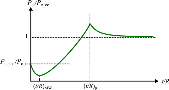
Figure 1. Schematic of the dimensionless critical load, Pc/Pc_co, vs. dimensionless coating thickness, t/R, for a single-layer coated sphere flattened by a rigid flat.
In the figure at t/R = 0, Pc = Pc_su and at very large t/R, Pc approaches Pc_co as expected. At ultralow t/R, a weakening effect exists such that Pc is lower than Pc_su. Maximum weakening occurs at t/R = (t/R)MW, and the location of yield inception is at the substrate side of the coating/substrate interface (Goltsberg and Etsion, 2013). As argued by Goltsberg and Etsion (2013), the contribution to the equivalent von Mises stress, σeq, due to the external normal loading is maximum slightly below the contact interface. The contribution due to the Young's moduli mismatch is maximum at the coating/substrate interface. At t/R = (t/R)MW the above two locations coincide and the maximum weakening occurs. Under a given normal load P, when t/R is different than (t/R)MW, the coating/substrate interface moves away from the location of maximum contribution from the external loading. This results in lower equivalent von Mises stresses and a higher Pc is needed for yielding as seen in Figure 1. The critical load Pc/Pc_co reaches a maximum at t/R = (t/R)p, when the location of yield inception moves to within the coating. Near (t/R)p, a strengthening effect is observed as Pc is greater than Pc_co.
Figure 2 schematically presents a bilayer coated sphere compressed by a rigid flat under normal load P. The radius of the spherical substrate is R. The bilayer coating has a total thickness t, and consists of a middle-layer and outer-coating of thicknesses t1 and t2, respectively (t = t1+t2). The bottom surface of the sphere is restricted from normal displacement [further restriction of tangential displacement has negligible effect on the results of the contact problem (Goltsberg et al., 2011)]. To simplify the problem, the following assumptions are adopted:
1. Perfect slip contact condition (frictionless) is assumed at the contact interface to avoid shear stresses there.
2. Perfect bonding is assumed at the outer-coating/middle-layer (OC/ML) and middle-layer/substrate (ML/S) interfaces.
3. The outer-coating, middle-layer and substrate materials are isotropic, free of residual stresses and obey linear elastic constitutive law prior to yielding.
4. The Poisson's ratio for outer-coating, middle-layer and substrate materials are equal, i.e. νco = νm = νsu = ν = 0.32. Note that the subscripts ‘co', ‘m', and ‘su' refer to the outer-coating, middle-layer and the substrate materials, respectively.
These simplifying assumptions help in providing a good physical insight of the problem but, if needed, can be relaxed in future work.
The contact problem shown in Figure 2 was solved by using the commercial package ABAQUS CAE 2017, with a 2D axisymmetric finite element model presented in Figure 3A. The bilayer coated sphere was modeled with a quarter circle and the rigid flat as a line. The quarter circle was meshed with 4-node bilinear quadrilateral elements (CAX4R) and the rigid flat was modeled with an ‘analytical rigid' element. The densest mesh was applied in a zone of 0.2t width and 1.2t depth at the sphere summit (see Figure 3B), where yield inception occurs. The element length in this zone is 0.005t. Outside this zone the mesh density is decreased gradually as seen in Figure 3A. In total, around 30,000 to 40,000 elements were used depending on the thicknesses of the outer-coating and middle-layer. To define the contact pair, the rigid flat surface was chosen as the master surface and the outer-coating surface as the slave surface, with “small sliding” formulation as the tracking approach [see section 38.1.1 of (Dassault Systémes, 2016) for details]. Loading of the coated sphere is accomplished by displacement control of the rigid flat, in increments of 4 × 10⁻⁷ R. Yield inception occurs in the bilayer coated sphere once the equivalent von Mises stress σeq (see Equation 2) at a certain location reaches the yield strength of the relevant material.
where σ1, σ2, and σ3 are the principal stresses. For all the cases studied here, yield inception was noted to occur along the axis of symmetry (x = 0), at which this expression becomes (Goltsberg et al., 2011)
where σ1 and σ2 are the normal and radial principal stresses, respectively.
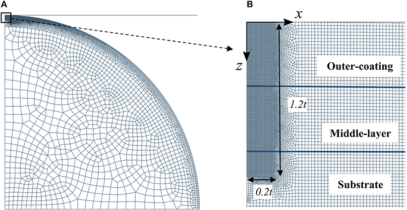
Figure 3. Finite element model of the bilayer coated sphere pressed by a rigid flat (A). Close-up of the mesh zone with highest element density (B). ML/S and OC/ML interfaces are highlighted in (B).
In order to validate the accuracy of the numerical model, mesh convergence was tested by running models with greater mesh density in all zones until no significant change (<1%) in the critical load at yield inception in the coated system is observed (see Appendix A for details). To validate the accuracy of the numerical model, identical material properties were applied to both the outer-coating and the middle-layer, corresponding to a single-layer coated sphere. The critical load as well as the load-displacement relation from such cases showed good agreement (within 10%) with the results reported by Goltsberg et al. (2011) and Goltsberg and Etsion (2015).
For studying the yield inception of a bilayer coated sphere, models were constructed such that Eco> Em>Esu and Yco > Ym > Ysu. In the models, R was fixed at 100 mm and Esu at 1 GPa. However, changing these dimensional values do not affect the results when presented in non-dimensional form. Simulations to study both the weakening and strengthening zones were run for t1/t from 0 to 1 in increments of 0.1, and t/R from 0.001 to 0.02 in increments of 0.0005. Since the value of peak critical load near the maximum strengthening is sensitive to t/R (see Figure 1), additional simulations were run near the peak strengthening with smaller t/R increments of 2 × 10⁻⁵. Note that the coating thickness in the present study is normalized by the substrate radius R, which is different from that normalized by half-width of the contact area, e.g., Komvopoulos (1988). Since R is known a priori, contrary to the unknown half width of contact area, which depends on load and coating thickness, the current normalization approach enables easy selection of the optimum coating thickness. The practicality and validity of this normalization approach was demonstrated experimentally in Bar-Hen and Etsion (2017). Moreover, this normalization approach was also used successfully in the study on the electrical conductance of a bilayer coated spherical contact (Korchevnik et al., 2018) and enabled a concise interpretation of the results for the application of electromechanical switches.
The material property ratios used in the models to study the strengthening effect are shown in Table 1. An extreme Eco/Esu = 10 was chosen to allow a substantial reduction in the Young's moduli mismatch by adding the middle-layer with Eco/Em = 1.82 and Em/Esu = 5.5. Figure 4 shows the dimensionless critical load Pc/Pc_co vs. the dimensionless coating thickness t/R for two typical bilayer cases of relatively small and large dimensionless middle-layer thicknesses t1/t = 0.4 and t1/t = 0.8, respectively. For comparison, results are also shown for t1/t = 0 corresponding to a single-layer case with coating made of the same outer-coating material (Eco/Esu = 10).
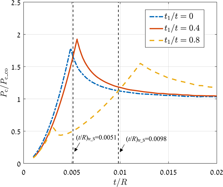
Figure 4. Dimensionless critical load, Pc/Pc_co, vs. dimensionless coating thickness, t/R, for bilayer coated spheres. Material properties as in Table 1.
For the small t1/t = 0.4, Pc/Pc_co increases monotonically with t/R until a maximum value (Pc/Pc_co)p at a certain t/R = (t/R)p and then reduces approaching unity, like the single-layer case. A similar behavior is shown for the large t1/t = 0.8, but this case involves an additional small peak at relatively small t/R. From Figure 4, it is noted that compared to the single-layer case with t1/t = 0, (Pc/Pc_co)p is greater for the bilayer case with t1/t = 0.4 but lower for the bilayer case with t1/t = 0.8. This suggests that the dimensionless middle-layer thickness, t1/t, can enhance or reduce the maximum strengthening of a coated sphere. Hence, there is an optimum t1/t at which the ultimate maximum strengthening effect is obtained.
Further, there is a transition thickness, (t/R)tr_S, for any t1/t at which the bilayer coated sphere has the same value of Pc/Pc_co as the single-layer coated sphere (see vertical dashed lines in Figure 4 for the cases with t1/t = 0.4 and t1/t = 0.8). While for t/R below its (t/R)tr_S, the bilayer coated sphere experiences lower critical loads than the single-layer coated sphere, for t/R above (t/R)tr_S the bilayer coated sphere experiences higher critical loads.
Figure 5 shows, for the strengthening zone, the effect of dimensionless middle-layer thickness, t1/t, on the peak critical load, (Pc/Pc_co)p, the dimensionless coating thickness at peak critical load, (t/R)p, and the dimensionless transition coating thickness, (t/R)tr_S. In Figure 5A, at t1/t = 0, which corresponds to a single-layer case, the peak dimensionless critical load is around 1.8 (see also Figure 4). As can be seen from Figure 5A, (Pc/Pc_co)p hardly changes up to t1/t = 0.3. Therefore, the bilayer effect in this range is negligible. An increase is noted for t1/t ≥ 0.3 and the ultimate peak critical load is at an optimum dimensionless middle-layer thickness t1/t = 0.5. The optimum t1/t value may be different for other material properties and this will be explored in a future study. Beyond the optimum t1/t, (Pc/Pc_co)p decreases and can even become lower than that for the single-layer case.
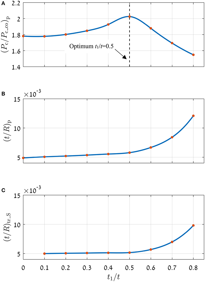
Figure 5. Peak dimensionless critical load, (Pc/Pc_co)p (A), dimensionless coating thickness at peak critical load, (t/R)p (B), and dimensionless transition coating thickness, (t/R)tr_S (C), for different middle-layer dimensionless thickness, t1/t. Material properties as in Table 1.
Further, from Figures 5B,C both (t/R)p and (t/R)tr_S become significantly large for t1/t larger than the optimum value. Hence, bilayer coatings with large values of t1/t are undesirable since the required total coating thickness, t, to obtain peak strengthening becomes very large, while the resulting peak strengthening is lower than the ultimate peak critical load at optimum t1/t.
In the present model, yield inception always occurs along the symmetry axis (x = 0 in Figure 2). From the many simulations performed in this study it was found that the location of yield inception in the bilayer cases depends on t1/t and t/R. With t1/t up to the optimum value (≤ 0.5) the yield inception is at the substrate side of the ML/S interface when t/R < (t/R)p, and within the outer-coating when t/R≥ (t/R)p. This is similar to the location of yield inception for single-layer coated cases as described in Goltsberg et al. (2011).
With t1/t greater than the optimum value (>0.5), the yield inception is also at the substrate side of the ML/S interface for low t/R. However, when t/R starts increasing the yield inception location jumps to the middle-layer side of the OC/ML interface. This jump corresponds to the first peak for the case with t1/t = 0.8 in Figure 4. When t/R further increases to its (t/R)p the yield inception location jumps to within the outer-coating. This corresponds to the second peak for the case with t1/t = 0.8 in Figure 4.
As seen in Figure 5A, for t1/t up to the optimum t1/t (≤ 0.5), an increase in t1/t leads to an increase in the dimensionless critical load (Pc/Pc_co)p, obtained at (t/R)p, when the yield inception location jumps to within the outer-coating. As explained in Goltsberg et al. (2011), at a given load, Young's moduli mismatch between the outer-coating and the substrate causes additional stresses within the outer-coating that is stretched by the substrate. As found from the present simulations, these additional stresses are reduced by increasing the thickness of the middle-layer and hence, (Pc/Pc_co)p is increased.
The two main sources for maximum contribution to the von Mises equivalent stress (Goltsberg and Etsion, 2013) were explained in the discussion of Figure 1 at the end of the Theoretical Background section. In the present study of bilayer coated spherical contact under a normal load P, the center point (x = 0) of the OC/ML interface is the location of maximum contribution to the von Mises equivalent stress due to the Young's moduli mismatch at this interface. For any given t/R, when t1/t increases, this location becomes closer to the contact area (see Figure 2) and the location of maximum contribution due to the normal loading. Hence, if the increasing von Mises equivalent stress at the OC/ML interface reaches the lower yield strength of the middle-layer, yield inception will occur at this point and the load P will become the critical one Pc. As we found from our simulations this occurs for a range of t/R values below (t/R)p whenever t1/t is greater than the optimum value (>0.5). For these values of t1/t, yield inception for a range of t/R is at relatively low critical loads, compared to the case with optimum t1/t. This results in a reduction of the (Pc/Pc_co)p value as seen in Figure 5A.
As discussed in relation to Figure 4, a bilayer coated case has lower critical loads than the corresponding single-layer case with same outer-coating (Eco/Esu = 10) and t/R, when t/R < (t/R)tr_S and greater critical loads when t/R > (t/R)tr_S. To investigate the reasons for this, comparisons were made between the dimensionless von Mises equivalent stresses, σeq/Y, along the axis of symmetry (at x = 0) in bilayer cases and corresponding single-layer cases. Y is the yield strength of the relevant material. The comparisons were done for each bilayer case and its corresponding single-layer case subjected to the lower critical load of the two cases.
The comparisons showed that the maximum σeq/Y in the outer-coating is typically lower in a bilayer case than in its corresponding single-layer case (except for locations next to the OC/ML interface at z/t = t2/t). The parameter z is the axial distance from the contact interface of the coated sphere as shown in Figure 2. However, the σeq/Y at the middle-layer side of the z/t = t2/t interface is typically significantly higher in a bilayer case than the σeq/Y at the same z/t location in its corresponding single-layer case. Further, the σeq/Y at the substrate side of the z/t = 1 interface is also typically higher in a bilayer case than in its corresponding single-layer case. This suggests in the strengthening zone, reducing the mismatch at z/t = 1 interface, by inserting a middle-layer, increases the σeq/Y at the substrate side of this interface.
The lower σeq/Y within the outer coating in a bilayer case compared to the corresponding single-layer case is due to the reduction of stresses within the outer-coating with the presence of the middle-layer, as discussed earlier. The bilayer case experiences additional stresses at z/t = t2/t due to the mismatch at the OC/ML interface at this location, which is not present in the corresponding single-layer case. Further, the material at the middle-layer side of the OC/ML interface in the bilayer case has lower yield strength than the outer-coating material at this z/t location in the single-layer case. Due to both of these reasons, σeq/Y at the middle-layer side of z/t = t2/t interface is higher in the bilayer case than the σeq/Y at the same z/t location in the corresponding single-layer case.
From the many simulations, it was observed that small mismatch at the z/t = 1 interface increases (makes more compressive) σ1 more than σ2 at the substrate side of the interface. From Equation (3) we can see that this increases σeq in the bilayer case compared to the single-layer case.
When t/R < (t/R)tr_S, high σeq/Y at either z/t = t2/t or z/t = 1 results in lower critical loads for a bilayer case compared to the corresponding single-layer case. When t/R > (t/R)tr_S, high σeq/Y within the outer-coating of the corresponding single-layer case results in smaller critical loads for this case compared to the bilayer case as seen in Figure 4.
Weakening occurs for coated spheres when Pc/Pc_su < 1. As per Equation (12) in Goltsberg and Etsion (2013), weakening for single-layer coated spheres occurs for small coating thickness when
Hence, to avoid constructing models with very low t/R, which would require a very dense mesh, models were constructed with a lower value of Esu/Ysu to study the weakening effect in bilayer coatings. Table 2 shows the material property ratios used in these models. The value of Esu/Ysu was chosen to be within the range analyzed by Goltsberg and Etsion (2013) for the weakening effect in single-layer coated spheres. Esu was kept the same as the value used in strengthening (1 GPa) and the Esu/Ysu ratio was reduced by increasing Ysu.
As noted by Goltsberg and Etsion (2013), the weakening effect in the single-layer case is due to additional stresses in the substrate due to the mismatch at the z/t = 1 interface. Hence, for more effective bilayer, Em/Esu = 2 was selected in Table 2 instead of 5.5 in Table 1. The yield strengths values of the outer-coating and the middle-layer materials were changed so that Yco/Ysu = Eco/Esu, and Ym/Ysu = Em/Esu as in Table 1.
Figure 6 presents Pc/Pc_su vs. t/R in the weakening zone for the same two typical cases of bilayer coated spheres, t1/t = 0.4 and t1/t = 0.8, as in Figure 4. Plots are also provided for single-layer coated cases with t1/t = 0 and t1/t = 1, which correspond to single-layer coatings with Eco/Esu = 10 and Eco/Esu = 2, respectively.
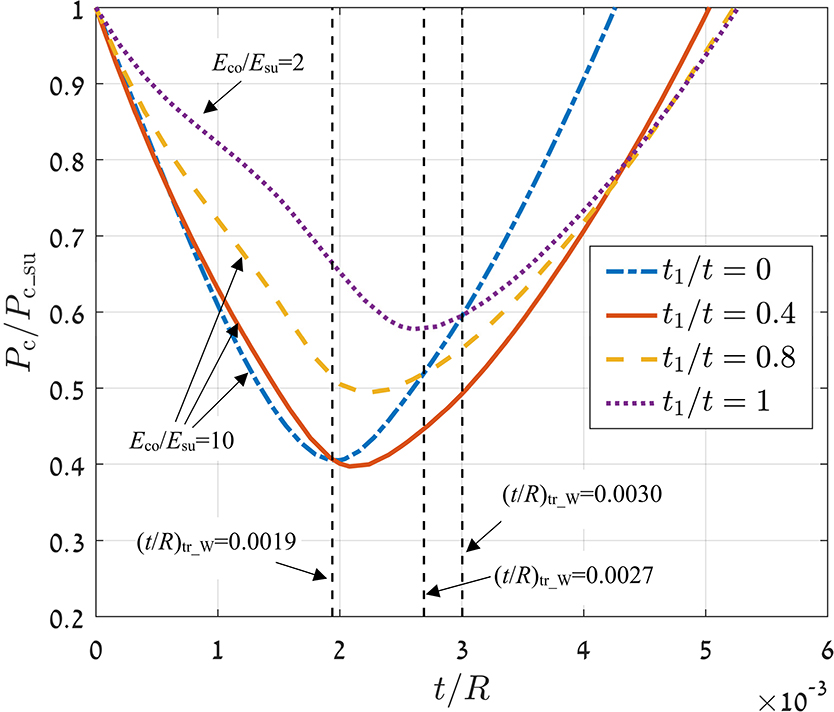
Figure 6. Dimensionless critical load, Pc/Pc_su, vs. dimensionless coating thickness, t/R. Material properties as in Table 2.
As shown in Figure 6, the single-layer case with higher mismatch (Eco/Esu = 10) has greater maximum weakening than the case with less mismatch (Eco/Esu = 2), consistent with Goltsberg and Etsion (2013). However, it is interesting to note that beyond a transition thickness (t/R)tr_W = 0.0030 the single-layer case with high mismatch Eco/Esu = 10 shows less weakening than the single-layer case with small mismatch Eco/Esu = 2. The two bilayer cases with t1/t = 0.4 and t1/t = 0.8 also exhibit greater weakening than the single-layer case t1/t = 0 for t/R beyond respective (t/R)tr_W values.
Further, in Figure 6 it is noted that the extension of the weakening zone, in terms of t/R, is smaller in the single-layer case with greater mismatch (Eco/Esu = 10) than for the two bilayer cases and the single-layer case with less mismatch (Eco/Esu = 2). This suggests that while a lower mismatch at the z/t = 1 interface is beneficial in reducing the maximum weakening, it adversely extends the weakening zone to higher t/R values.
Considering the results in the Strengthening Effect of Bilayer Coated Spheres section, a bilayer coated sphere has a higher critical load than a single-layer case with the same outer-coating when t/R is either above (t/R)tr_S or below (t/R)tr_W. Since the second case has to be avoided as being inside the weakening zone, the preferred selection for the total coating thickness of a bilayer case would be t/R > (t/R)tr_S.
Figure 7 shows dimensionless critical load at maximum weakening, (Pc/Pc_su)MW, for bilayer coated spheres with different t1/t. As can be seen from Figure 7 (Pc/Pc_su)MW hardly changes up to t1/t = 0.4. Therefore, the bilayer effect in this range is negligible. For t1/t > 0.4, the bilayer cases show less maximum weakening than the single-layer case with t1/t = 0 but greater weakening than the single-layer case with t1/t = 1.
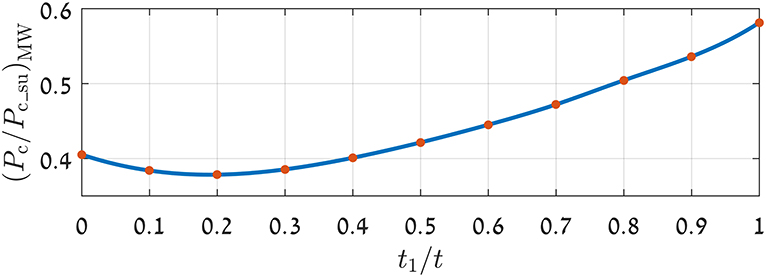
Figure 7. Dimensionless critical load at maximum weakening, (Pc/Pc_su)MW, for different t1/t. Material properties as in Table 2.
In the weakening zone, at very low t/R, yield inception is within the substrate. For t/R ≥ (t/R)MW, yield inception is at the substrate side of the ML/S interface. This behavior was noted for all bilayer coated spheres with different t1/t, and is similar to the behavior for single-layer coated spheres as described in Goltsberg and Etsion (2013).
In a previous study (Goltsberg et al., 2011) it was assumed that the Young's moduli mismatch is detrimental, in the weakening zone, due to a reduction in the compressive stresses at the substrate side of the coating/substrate interface. However, as seen in Figure 6, the single-layer case with high mismatch Eco/Esu = 10 exhibits less weakening than the other cases (that have less mismatch) at t/R beyond each relevant (t/R)tr_W. From the many simulations, it was observed that above (t/R)tr_W reducing the mismatch at the z/t = 1 interface increases σ1 more than σ2 at the substrate side of the interface (at x = 0). From Equation (3) we can see that this increases σeq in the bilayer case compared to the single-layer case.
This suggests reducing the mismatch at the z/t = 1 interface reduces the σeq /Y at the substrate side of the interface only for low t/R (when t/R is less than the relevant (t/R)tr_W).
Additional simulations were run for a range of material properties described in Table 3. Within this range, it is noted
1) The bilayer coated sphere exhibits greater strengthening than the corresponding single layer case only when t/R is greater than a transition thickness (t/R)tr_S.
2) There exists optimum values of t1/t and t/R for ultimate peak strengthening.

Table 3. Range of parameters for which similar behavior as described in the Strengthening Effect of Bilayer Coated Spheres section was observed (Yco/Ysu = Eco/Esu and Ym/Ysu = Em/Esu).
Hence, the general observations made here are likely to be applicable for the design of real coating systems, particularly those with Eco/Esu ratios within this range. For example, Eco/Esu for TiN outer-coating on Ti substrate is 3.33, and TiN outer-coating on Al substrate is 5.71 (Sun et al., 1995). Likewise, the ratio E/Y for most engineering metallic materials ranges from 100 to 2000, so the cases covered by Table 3 are in line with practical applications.
Due to the large number of material and dimensional parameters, finding quantitative expressions between the material properties and the optimum values of t1/t and t/R is beyond the scope of this paper. It shall be attempted in a future study.
Yield inception of bilayer coated spheres, with a middle-layer of intermediate Young's modulus and yield strength, flattened by a rigid flat was studied for a range of dimensionless thicknesses of the two layers. Both the strengthening and weakening effects were observed for bilayer coated spheres. It was expected that the gradual reduction of the Young's moduli mismatch in the bilayer coating would enhance the critical loads for yield inception over a single-layer coated sphere with the same outer-coating. However, the results show that within the strengthening zone, the presence of a middle-layer leads to an increase in the critical load only when the total dimensionless coating thickness is above a certain transition value, (t/R)tr_S, which depends on the material properties and the dimensionless thickness of the middle-layer, t1/t. Further, there is an optimum dimensionless middle-layer thickness t1/t, which maximizes the peak critical load (Pc/Pc_co)p of a bilayer coated sphere.
In addition, it is shown that there exists a (t/R)tr_W within the weakening zone above which the bilayer coated case experiences lower critical loads than the single-layer case with the same outer-coating. This implies that bilayer coatings are undesirable when (t/R)tr_W < t/R < (t/R)tr_S.
It is therefore recommended to select t/R > (t/R)tr_S for beneficial effect of bilayer coated spheres. Finding the expressions for the optimum t1/t and optimum t/R as functions of material properties requires a complex parametric analysis, which is out of the scope of the present paper but will be attempted in a future study.
The datasets generated for this study are available on request to the corresponding author.
KP, ZC, and IE conceptualized, wrote, reviewed, and edited the manuscript. KP wrote the original draft. IE supervised. All authors have read and agreed to the published version of the manuscript.
The authors declare that the research was conducted in the absence of any commercial or financial relationships that could be construed as a potential conflict of interest.
This paper is part of IEA AMT IA technical activities.
The Supplementary Material for this article can be found online at: https://www.frontiersin.org/articles/10.3389/fmech.2020.00023/full#supplementary-material
Bar-Hen, M., and Etsion, I. (2017). Experimental study of the effect of coating thickness and substrate roughness on tool wear during turning. Tribol. Int. 110, 341–347. doi: 10.1016/j.triboint.2016.11.011
Brizmer, V., Kligerman, Y., and Etsion, I. (2006). The effect of contact conditions and material properties on the elasticity terminus of a spherical contact. Int. J. Solids Struct. 43, 5736–5749. doi: 10.1016/j.ijsolstr.2005.07.034
Chai, H., Lawn, B. R., and Wuttiphan, S. (1999). Fracture modes in brittle coatings with large interlayer modulus mismatch. J. Mater. Res. 14, 3805–3817. doi: 10.1557/JMR.1999.0514
Dassault Systémes (2016). Abaqus. Analysis User's Guide. Available online at: http://ivt-abaqusdoc.ivt.ntnu.no:2080/v2016/books/usb/default.htm?startat=pt06ch32s05ael30.html
Djabella, H., and Arnell, R. D. (1993a). Finite element analysis of contact stresses in elastic double-layer systems under normal load. Thin Solid Films 223, 98–108. doi: 10.1016/0040-6090(93)90732-5
Djabella, H., and Arnell, R. D. (1993b). Finite element comparative study of elastic stresses in single, double layer and multilayered coated systems. Thin Solid Films 235, 156–162. doi: 10.1016/0040-6090(93)90259-R
Djabella, H., and Arnell, R. D. (1994). Finite element analysis of elastic stresses in multilayered systems. Thin Solid Films 245, 27–33. doi: 10.1016/0040-6090(94)90872-9
Fontalvo, G. A., Daniel, R., and Mitterer, C. (2010). Interlayer thickness influence on the tribological response of bi-layer coatings. Tribol. Int. 43, 108–112. doi: 10.1016/j.triboint.2009.05.002
Goltsberg, R., and Etsion, I. (2013). A model for the weakening effect of very thin hard coatings. Wear 308, 10–16. doi: 10.1016/j.wear.2013.09.019
Goltsberg, R., and Etsion, I. (2015). A universal model for the load-displacement relation in an elastic coated spherical contact. Wear 322–323, 126–132. doi: 10.1016/j.wear.2014.11.002
Goltsberg, R., Etsion, I., and Davidi, G. (2011). The onset of plastic yielding in a coated sphere compressed by a rigid flat. Wear 271, 2968–2977. doi: 10.1016/j.wear.2011.06.025
Guo, Y. X., and Zhao, Y. W. (2019). Effect of interlayer on the elastic-plastic deformation of coating systems. J. Mech. 35, 1–8. doi: 10.1017/jmech.2018.46
Gupta, P. K., and Walowit, J. A. (1974). Contact stresses between an elastic cylinder and a layered elastic solid. J. Lubr. Technol. 96, 250–257. doi: 10.1115/1.3451940
Huang, X., Kasem, H., Shang, H. F., Shao, T. M., and Etsion, I. (2012). Experimental study of a potential weakening effect in spheres with thin hard coatings. Wear 296, 590–597. doi: 10.1016/j.wear.2012.08.018
Komvopoulos, K. (1988). Finite Element Analysis of a layered elastic solid in normal contact with a rigid surface. J. Tribol. 110, 477–485. doi: 10.1115/1.3261653
Komvopoulos, K. (1989). Elastic-plastic finite-element analysis of indented layered media. J. Tribol. 111, 430–439. doi: 10.1115/1.3261943
Korchevnik, O., Goltsberg, R., Kligerman, Y., and Etsion, I. (2018). Electrical resistance model of a bilayer-coated spherical contact. IEEE Trans. Compon. Packag. Manuf. Technol. 8, 1614–1620. doi: 10.1109/TCPMT.2018.2854755
Kot, M. (2012). Contact mechanics of coating-substrate systems: monolayer and multilayer coatings. Arch. Civ. Mech. Eng. 12, 464–470. doi: 10.1016/j.acme.2012.07.004
Lardner, T. J., Giovinazzo, R. J., and Ritter, J. E. (1992). The effect of high modulus single and double layer coatings on contact stresses. Philos. Mag. A 66, 437–455. doi: 10.1080/01418619208201568
Liu, T. J., Xing, Y. M., and Wang, Y. S. (2016). The axisymmetric contact problem of a coating/substrate system with a graded interfacial layer under a rigid spherical punch. Math. Mech. Solids 21, 383–399. doi: 10.1177/1081286514555563
Piao, Z. Y., Xu, B. S., Wang, H. D., and Pu, C. H. (2010). Effects of thickness and elastic modulus on stress condition of fatigue-resistant coating under rolling contact. J. Cent. South Univ. Technol. 17, 899–905. doi: 10.1007/s11771-010-0574-5
Stephens, L. S., Liu, Y., and Meletis, E. I. (2000). Finite Element Analysis of the initial yielding behavior of a hard coating/substrate system with functionally graded interface under indentation and friction. J. Tribol. 122, 381–387. doi: 10.1115/1.555373
Sun, Y., Bloyce, A., and Bell, T. (1995). Finite element analysis of plastic deformation of various TiN coating/substrate systems under normal contact with a rigid sphere. Thin Solid Films 271, 122–131. doi: 10.1016/0040-6090(95)06942-9
van der Zwaag, S., Dear, J. P., and Field, J. E. (1986). The effect of double layer coatings of high modulus on contact stresses. Philos. Mag. A 53, 101–111. doi: 10.1080/01418618608242810
van der Zwaag, S., and Field, J. E. (1982). The effect of thin hard coatings on the Hertzian stress field. Philos. Mag. A 46, 133–150. doi: 10.1080/01418618208236213
Yu, C., Wang, Z., Liu, G., Keer, L. M., and Wang, Q. J. (2016). Maximum von Mises stress and its location in trilayer materials in contact. J. Tribol. 138:041402. doi: 10.1115/1.4032888
Keywords: contact mechanics, yield inception, coatings, bilayers, strengthening and weakening
Citation: Parel KS, Chen Z and Etsion I (2020) Strengthening and Weakening Effects in Bilayer Coated Spherical Contact. Front. Mech. Eng. 6:23. doi: 10.3389/fmech.2020.00023
Received: 27 February 2020; Accepted: 09 April 2020;
Published: 29 April 2020.
Edited by:
Valentin L. Popov, Technical University of Berlin, GermanyReviewed by:
Antonio Papangelo, Politecnico di Bari, ItalyCopyright © 2020 Parel, Chen and Etsion. This is an open-access article distributed under the terms of the Creative Commons Attribution License (CC BY). The use, distribution or reproduction in other forums is permitted, provided the original author(s) and the copyright owner(s) are credited and that the original publication in this journal is cited, in accordance with accepted academic practice. No use, distribution or reproduction is permitted which does not comply with these terms.
*Correspondence: Izhak Etsion, ZXRzaW9uQHRlY2huaW9uLmFjLmls
Disclaimer: All claims expressed in this article are solely those of the authors and do not necessarily represent those of their affiliated organizations, or those of the publisher, the editors and the reviewers. Any product that may be evaluated in this article or claim that may be made by its manufacturer is not guaranteed or endorsed by the publisher.
Research integrity at Frontiers

Learn more about the work of our research integrity team to safeguard the quality of each article we publish.