- 1Research Centre for Fire Engineering, The Hong Kong Polytechnic University, Kowloon, Hong Kong
- 2The Hong Kong Polytechnic University Shenzhen Research Institute, Shenzhen, China
- 3Department of Mechanical Engineering, University of California, Berkeley, Berkeley, CA, United States
- 4United States Forest Service, United States Department of Agriculture (USDA), Rocky Mountain Research Station, Missoula Fire Sciences Lab, Missoula, MT, United States
Recent mega wildfires have become one of the most dangerous and devastating hazards, with a wide range of negative impacts on the economy, society, and environment. As cylindrical shrubs and twigs are typical fuel loads in wildfires, it is important to understand how the diameter and arrangement of cylindrical fuels affect their ignition behaviors. In this work, the piloted ignition of cylindrical wood rods with different diameters (3.2 ~15.9 mm) are conducted under the irradiation up to 50 kW/m2. Three fuel groups are tested: (I) single vertical rod, (II) single horizontal rod, and (III) horizontal rod bed attached to the ground. For a single vertical rod, the measured ignition time decreases as the diameter is decreased from 15.9 to 6.4 mm, showing a thermally-thin behavior. However, the ignition of the 3.2-mm rod is more difficult than the 9.5-mm rod, because of the enhanced convective cooling by the larger curvature. Nevertheless, when the rod fuels are placed horizontally on the ground, the curvature-enhanced convective cooling becomes limited. For a single rod, when both the fuel diameter and the irradiation are small, only smoldering ignition occurs, and eventually the sample collapses. For the rod bed, flaming ignition always occurs, and it is easier to ignite because of a smaller convective cooling. For both horizontal configurations, the fuel ignition temperature increases almost linearly with the diameter from 270°C (3.2 mm) to 330°C (15.9 mm) but is insensitive to the irradiation level. This research quantifies the effect of fuel diameter and arrangement on the piloted ignition and reveals that the traditional classification of thermally thin and thick fuel for flat materials may not be suitable for cylindrical wildland fuels.
Introduction
Over the past few decades, the size, frequency, and severity of wildfires show a steep increase due to the demographic and climatic changes all over the world, despite the significant development of the fire prevention and suppression technologies (Liu et al., 2010; McClure and Jaffe, 2018; Toledo et al., 2018). Wildfires refer to the unmanageable and unpredictable fires which are free to spread and expand, thus causing severe damage and loss to the economy, society and environment (Jolly et al., 2015; Leuenberger et al., 2018; Montiel Molina et al., 2019). For example, serious wildfires in 2017 swept across British Columbia, Canada; California, USA; Southern Europe, especially in Portugal and Italy, causing more than 100 fatalities in July (Ronchi et al., 2017). Dead vegetation particles can constitute a bulk of surface fuel loads, so they are closely related to the fire risks and hazards in wildlands (Moghtaderi et al., 1997). Therefore, it is of vital importance to fully understand the fire risks and dynamics of the woody particles for the improvement and innovation of wildfire protection measures (Shen et al., 2013).
The ignition of wildland fuels has been widely studied to associate with the initiation and growth of the devastating wildfires (Moghtaderi et al., 1997; Boonmee and Quintiere, 2005). Fundamentally, the fire spread is a continuous ignition process that is heated and piloted by the flame (Williams, 1977). Both extrinsic (e.g., heating source, oxygen concentration and wind velocity) and intrinsic (e.g., density, composition, moisture, and age) factors can affect the ignitability and flammability of vegetations. Therefore, for different vegetation types, there are different ignition criteria and forms, e.g., piloted or auto-ignition, and flaming or smoldering ignition (Tuyen et al., 1995). For high-density wood particle, the ignition difficulty or the ignition delay time under the external irradiation generally increases from the piloted flaming ignition to flaming autoignition, and then, to smoldering (or glowing and surface) ignition (Boonmee and Quintiere, 2002), but for low-density fuel, the smoldering ignition becomes easier (Lin et al., 2019).
Most literature works studied the ignition of flat materials and depending on the level of irradiation (or radiant heat flux), thermally thick and thin materials can be identified (Drysdale, 1986). In general, based on the thermally-thin theory of flat fuel, only when the sample thickness is <1 mm, the ignition delay time will start to increase with sample thickness (Quintiere, 2006). Comparatively, much fewer studies have addressed the ignition of fuel with shapes other than flat, e.g., the cylindrical, spherical, or amorphous shapes. The cylindrical fuels are dominant in the wildland surface fires, e.g., shrubs, twigs and pine needles, as shown in Figure 1. Fons (1950) first studied the auto-ignition mechanism of wood cylinders inside a hot furnace and revealed the ignition time increased with the sample diameter. Several analytical and empirical expressions of the ignition delay time as a function of diameter and critical irradiation have been derived for cylindrical fuels (Delichatsios, 2000; Hernández et al., 2019). McAllister and Finney (2017) investigated the auto-ignition of small wood cylinders with a diameter of 6.4~19.1 mm under the combined convective and radiative heating, and showed that the auto-ignition delay time increased with the wood diameter. Recent researches revealed the dominant ignition mechanism of fine wildland fuel particles (diameter ≤ 1 mm, e.g., pine needle) is convective heating by the hot fire plume or the direct flame contact, rather than the radiant heat in Rothermel's model (Finney et al., 2013, 2015). Fundamentally, this is because for fine fuel like pine needles, convective cooling increases significantly with a smaller diameter or a larger curvature that overcomes the radiant heating effect (Incropera, 2007). However, how the diameter of small and medium cylindrical wildland fuels (>1 mm) affects the piloted ignition behavior; and what is the critical diameter for convective cooling to be dominant is still not clear. Moreover, no study in the literature has investigated the different piloted ignition behaviors between the single fuel particle and a fuel bed of multiple particles, thus bringing a huge research gap.
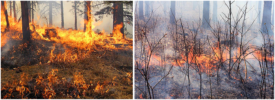
Figure 1. Typical wildland surface fire with cylindrical fuels (Credit: Benjamin Knapp/University of Missouri).
In this work, the piloted ignition of cylindrical wood rods with diameters of 3.2 ~15.9 mm are tested under the irradiation up to 50 kW/m2. Three groups of ignition experiments, (I) single vertical rod, (II) single horizontal rod, and (III) horizontal rod bed attached to the ground, are performed to study the diameter effect. The ignition phenomena, delay time, and ignition temperature will be analyzed.
Experiment
Wood Rod Sample
Cylindrical wood rods (~8 cm in length) with four different diameters, 15.9, 9.5, 6.4, and 3.2 mm (or 5/8, 3/8, 1/4, and 1/8 in), were used in the experiment, as shown in Figure 2A. Note that they are relatively thicker than the conventional fine particles (< 1 mm) (Finney et al., 2013, 2015). Before the experiment, wood rods were first dried at 70°C in the oven for 48 h, and the dry bulk density of rod was measured as ~650 kg/m3. For the rod bed tests, the wood rods were arranged one against the other without space, as shown in Figure 2B, which was to mimic a packed fuel on the wildland surface. As the diameter of the wood rod decreased, the number of wood rods per unit area increased. In particular, as the diameter increased from 3.2 to 15.9 mm, the number of wood rods in the fuel bed decreased from 25 to 7, as seen in Figure 2B.

Figure 2. (A) Cylindrical wood samples with different diameters, and (B) examples of the array of the rod bed.
Vertical Rod Test
For the single vertical rod test (Group I), the test section was enclosed by a 25.4 cm long Pyrex glass tube with an outer diameter of 75 mm and an inner diameter of 70 mm, as shown in Figure 3I. The vertically oriented cylindrical rod sample was centered in the test section. Three quartz near-infrared halogen tungsten filament lamps (Ushio QIH120-500T/S, 12.7 cm long) were installed with 120° interval to provide more uniform irradiation around the cylindrical wood rod. The average irradiation from 3 lamps to the axial rod surface (), up to 35 kW/m2, was measured by a Schmidt-Boelter radiometer (MEDTHERM Co.) and calibrated with the power supply to be approximately uniform (Hernández et al., 2019). It is expected that most of the irradiation will be absorbed on the fuel surface, i.e., negligible in-depth radiation. To ensure a good air supply to the test section, a small airflow of 25 cm/s was supplied from the bottom of the glass tube throughout the heating process. This experimental setup is the same as the past work on the ignition of electrical wire (Miyamoto et al., 2016).
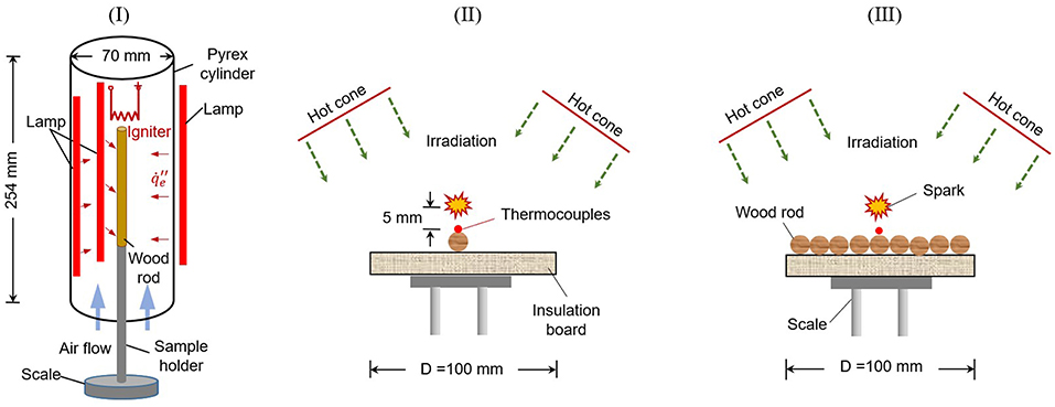
Figure 3. Schematic diagrams for three groups of ignition tests, (I) the single vertical rod, (II) the single horizontal rod, and (III) the horizontal rod bed.
The ignition process involved turning on the halogen lamps without preheating, because halogen lamp has a quick response to the change of supply power. To fix the sample position, the sample was hung by a hook from the top or supported by a base and a side sample holder. The ignition was achieved by using a hot electrical coil or a ceramic heater, placed 5 mm above the rod. To prevent the direct heating from the igniter, the top of the rod was covered by the aluminum foil. Flaming ignition was considered to have failed if the flame did not occur after heating for 30 min. Then, the irradiation was adjusted to find the critical (or minimum) irradiation for flaming ignition (). All experiments were repeated at least twice to reduce the random error.
Horizontal Rod Test
Another two piloted ignition tests of the single horizontal rod (Group II) and horizontal rod bed (Group III) were conducted with the cone calorimeter (FTT iCone Plus) (Babrauskas, 2016), mainly composed of a conical heater, a spark igniter, and a sample holder, as illustrated in Figures 3II,III. The conical heater could provide constant irradiation () to the sample area of 10 × 10 cm. During the experiments, the horizontal wood rods were attached to the insulation board without bonding material, mainly to mimic the dead wildland fuel on the surface, different from the floating samples like pine needles and tree twigs (Finney et al., 2013; McAllister and Finney, 2017). Moreover, compared to the vertical rod receiving more uniform surface irradiation, only half of horizontal rod surface receives irradiation. Before the test, the temperature of the conical heater was set at a certain value to generate the correspondingly uniform irradiances over the entire exposed face of the specimens, which was measured and calibrated by a radiometer. The test section (fuel and cone heater) was not enclosed to ensure a good air supply.
A spark was used as the igniter, and the position of spark igniter was adjusted for different rod diameters to ensure that it was located at 5 mm above the top surface of each rod. A 10 × 10 cm insulation board was placed below the horizontal rods. The radiant heating would start when the shield of the conical heater was removed. The surface temperature was monitored by a K-type thermocouple with 0.5-mm bead that was in good contact with the rod top surface. The heating process, the moment of flaming ignition, and the following burning process were captured by a video camera. Once the flaming ignition occurred, the spark igniter was removed, while the heating was continued until the flaming burning process ended. For each test condition, at least two repeating experiments were conducted to characterize the ignition behaviors and uncertainty.
Results and Discussions
Ignition Phenomena and Critical Irradiation
Figure 4 shows the typical ignition phenomena of the single vertical rod test (Group I), where the original videos can be found in Supplementary Videos 1–3. Figure 5 shows the examples of the piloted ignition process of the single horizontal wood rod (Group II) as well as the wood rod bed (Group III, Supplementary Videos 4–7). Before the ignition, smoke was always observed, likely the pyrolysis gases. Figure 5 also shows a common charring process at the low irradiation of 15 kW/m2 for all tested rods, where the wood surface turned to black and was bent. This is because a minimum mass flux of pyrolysis gas is required for the spark igniter to pilot a flame (Rich et al., 2007). However, before reaching the minimum mass flux of flaming ignition, a slow pyrolysis or charring process has already taken place under such a long period of slow heating. In contrast, as the heating flux increased to 50 kW/m2, there is negligible charring and bending process before the ignition, as shown in Figure 5B.
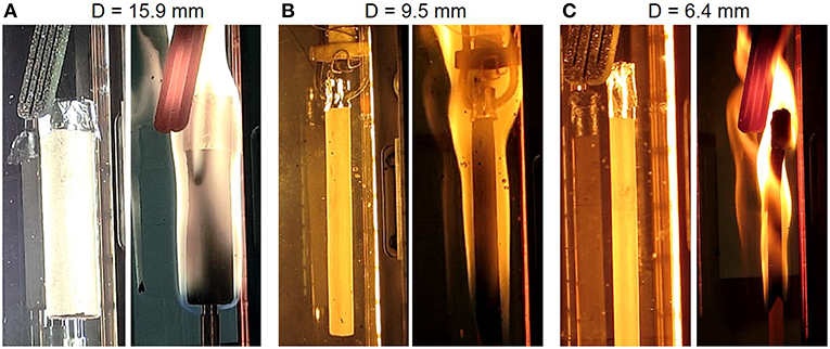
Figure 4. Piloted flaming ignition process of test Group (I) single vertical rod under the irradiation of 20 kW/m2, (A) D = 15.9 mm, (B) D = 9.5 mm, and (C) D = 6.4 mm.
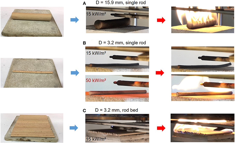
Figure 5. Piloted flaming ignition process of horizontally placed wood rods, (A) D = 15.9 mm, single rod, 15 kW/m2, (B) D = 3.2 mm, single rod, 15 kW/m2 and 50 kW/m2, (C) D = 3.2 mm, rod bed, 15 kW/m2, where the snapshots in the middle are 5 s before the ignition if it occurs.
If the irradiation decreases to a certain value, no flaming ignition could occur after heating for 30 min. Such value is defined as the critical irradiation (), and can be explained by a thermal equilibrium with the environmental heat loss () right below the ignition temperature (Tig) (Drysdale, 2011) as:
where Ta is the ambient temperature, hc and hr are the convective and radiative cooling coefficient, respectively. Figures 6, 7 summarizes the measured critical irradiation for all three test groups. For (I) the single vertical rod in Figure 6A, for the rod diameters between 6.4 and 15.9 mm, the required minimum irradiation are essentially the same, as kW/m2. However, for the thinnest rod (3.2 mm), no flaming ignition would occur below the irradiation of 20 kW/m2, because the sample was charred, smoldered into ash, and eventually collapsed. A similar phenomenon also occurred to (II) the single horizontal rod in Figure 7A, where the critical irradiation increases from 13 kW/m2 (9.6 and 15.9 mm) to 17 kW/m2 (3.2 and 6.4 mm). Therefore, as compared in Figures 5A,B, at the low irradiation of 15 kW/m2, flaming ignition occurs to 15.9-mm rod, while not to the 3.2-mm rod.
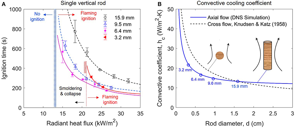
Figure 6. The ignition delay time of (A) single vertical rod, and (B) convective cooling coefficient of rod sample, where convective cooling coefficient for axial flow is calculated via DNS simulation in FDS, and the convective cooling coefficient for cross-flow is calculated via empirical correlation from Knudsen and Katz (1958).
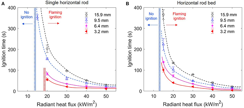
Figure 7. The ignition delay time of (A) the single horizontal rod (Group II), and (B) the horizontal rod bed (Group III).
In contrast, for (III) the packed rod bed in Figure 7B, the critical irradiation is the same 13 kW/m2 for all rod diameters, probably because the rod bed is essentially similar to a flat wood plate. In other words, it is possible that in real wildland fires, discrete fuel particles of small diameter (~5 mm) may be ignited and burnt in the form of smoldering fire under a small or medium external radiation from the nearby fires, and they may never ignite with a flame. However, such phenomena may not occur to very small fuel diameters (<1 mm) which do not even smolder because of the strong convective cooling (Finney et al., 2013, 2015), or to a packed fuel bed on wildland surface.
Ignition Delay Time
Figure 6A compares the ignition delay time as a function of rod diameter for (I) the single vertical rod, and all the raw data are listed in the Table 1. Not surprisingly, the ignition delay time decreases as the irradiation increases, just like other common fuels (Drysdale, 2011).

Table 1. Measured flaming ignition delay time for the single vertical fuel (Group I), where the radiation level calibrates the change in the gap between lamp and rod due to the change in diameter.
Clearly, the ignition delay time increases as the diameter increases from 6.4 to 15.9 mm, but the values become more similar at higher heat fluxes. Therefore, it shows a similar trend of the thermally-thin flat material, although the diameter of rods is much larger than the traditional limit of thin flat material (<1 mm). This is mainly because regardless the diameter of the cylindrical fuel, it has a perfect adiabatic boundary condition in the axis, and two boundary conditions are similar to the classic thermally-thin sample (Quintiere, 2006), as:
Nevertheless, because of different coordinates, the ignition delay time of cylindrical fuels is not proportional to the diameter, different from that of thin flat fuels (proportional to the thickness).
Note that for rod diameter larger than 6 mm, the effect of the radius (or the curvature) on convective cooling coefficient is still relatively small, as illustrated in Figure 6B. Thus, the heating of cylindrical rod with different diameters is mainly controlled by the conduction. As a result, the cylindrical rod of a smaller diameter is easier to heat up, and more detailed heat-transfer analysis can be found in Delichatsios (2000) and Hernández et al. (2019). Thus, the traditional classification of thermally thin and thick fuel for flat fuel cannot be applied to cylindrical fuels in the wildlands.
Nevertheless, as the vertical rod diameter decreases to 3.2 mm in Figure 6A, its ignition delay time becomes larger than that of 6.4 and 9.5 mm, reversing the trend for diameter larger than 6.4 mm. This is because the convective cooling coefficient (hc) increases significantly as the diameter is decreased (Knudsen and Katz, 1958), especially below 5 mm, as shown in Figure 6B, thus, it may be expressed as:
where the index α quantifies the diameter (or curvature) effect. Therefore, when the rod diameter is smaller than a critical value of about 5 mm, the convective cooling starts to control the piloted ignition under radiation, and the ignition becomes more difficult than larger rod diameters.
However, care is needed to generalize such a conclusion for the size effect. Figure 7 shows that for the single horizontal rod or the horizontal rod bed on the ground (Groups II and III), the ignition delay time continuously decreases, as the rod diameter is decreased even to 3.2 mm. All the raw data are listed in Table 2. This is mainly because when the wood rod is attached to the ground, the convection flow field is significantly affected by the ground surface, rather than controlled by the curvature of the fuel, that is, a smaller α. Moreover, for the rod bed (Group III), the nearby rods not only limit the convective cooling area, but also reduce the curvature-enhanced convective cooling (i.e., closer to the flat sample). Thus, the convective cooling of each rod is further reduced, resulting in a shorter ignition delay time. For example, under 30 kW/m2, the ignition time is 60 s for a single 9.5-mm rod but reducing to 49 s for the rod bed. In other words, the curvature-enhanced convective cooling for three test groups ranks as αI > αII > αIII.

Table 2. Flaming ignition delay time for the single horizontal fuel (Group II) and the horizontal fuel bed (Group III).
Ignition Temperature
For the ignition criterion, it is a common practice to assume an ignition temperature (Tig), that is, flaming ignition will occur when the fuel surface temperature reaches a critical value (Quintiere, 2006), and such critical temperature is also most useful to predict the rate of fire spread (Atreya, 1998; Tian and Zhou, 2015). If the irradiation is below the critical value (), an equilibrium between radiant heating and environmental cooling will be reached at a surface temperature below Tig. Figure 8 shows the evolution of surface temperature for (A) the single horizontal rod, and (B) the rod bed with different diameters under the same 30 kW/m2. Once heated by irradiation, the surface temperature rapidly increases, while the rate of increase becomes smaller because of the increase in the environmental cooling. Afterwards, on the moment of flaming ignition, the surface temperature experiences a sudden jump. Clearly, under the same irradiation, the heating rate of the smaller particle is much faster, especially in Figure 8A. Nevertheless, the effect of diameter becomes smaller in the rod bed in Figure 8B, the overall top surface of the rod bed configuration becomes more smooth and closer to a flat sample compared to a single rod.
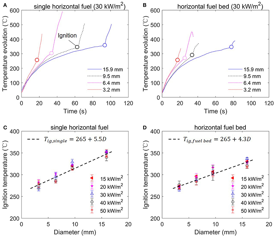
Figure 8. The temperature evolution of rod top surface (A) single horizontal rod, and (B) horizontal rod bed; and ignition temperature (Tig) as a function of rod diameter, (C) single horizontal rod, and (D) horizontal rod bed.
Figure 8 also summarizes the ignition temperature of (C) the single horizontal rod, and (D) the horizontal rod bed as a function of rod diameter and irradiation. It can be found that for both fuel arrangements, the ignition temperature increases with the rod diameter, but it is insensitive to the irradiation level. For example, for the single rod, the ignition temperature increases from about 280 to 350°C, as the rod diameter increases from 3.2 to 15.9 mm. Then, the empirical correlation can be obtained by fitting all the data points for the single horizontal rod as:
and for the horizontal rod bed as:
Note that these results disagree with the widely assumed constant ignition temperature for a given fuel that is slightly above its pyrolysis point.
One possible reason is that for a rod of the smaller diameter, both the received external radiation and the in-depth conduction are more uniform, leading to a smaller internal temperature gradient. Then, a thicker layer below the surface also has the temperature high enough to pyrolyze, so that sufficient fuel mass flux could be produced. Comparatively, for a rod of larger diameter, the in-depth temperature is much lower than the surface temperature. Only the thin surface layer is pyrolyzing, so that a higher surface (ignition) temperature is needed to reach the minimum fuel mass flux.
Moreover, the trend of ignition temperature also explains the constant critical irradiation of kW/m2 found in Figures 6, 7. Considering the convective cooling coefficient (hc) in Equation (3) decreases as the diameter is increased, with the compensation of the increasing ignition temperature (Tig), in Equation (1) will tend to remain as a constant. Comparatively, for the rod bed, a weaker diameter dependence of Tig in Equation (5) also compensates the weak diameter dependence of hc in Equation (3) where αIII is the smallest in all three test groups.
Conclusions
In this work, we found that for a single vertical rod, the piloted ignition time decreases as the diameter is decreased from 15.9 to 6.4 mm, showing a thermally-thin behavior. However, for the thinnest rod with a diameter of 3.2 mm, the ignition is more difficult, and its ignition time could be longer than that of the 9.5-mm rod. This is because the convective cooling is enhanced when the curvature of fuel is larger, i.e., the curvature effect. Thus, the traditional thermally-thin assumption may fail when the rod diameter is less than about 5 mm. Nevertheless, the arrangement of fuel also influences the piloted ignition behaviors. When the rod fuels are placed horizontally on the ground, such curvature enhanced convective cooling becomes limited.
For the single horizontal rod, when the diameter and irradiation are both small, only smoldering ignition occurs, and eventually the sample collapses. For the single rod with larger diameter and the rod bed, the critical irradiation of ignition is almost constant (13 kW/m2). For the rod bed, flaming ignition always occurs; the ignition behavior is closer to the flat sample; and its ignition is easier than single rod due to a smaller convective cooling. Moreover, for both horizontal configurations, the measured ignition temperature increases almost linearly from 270 to 330°C as the fuel diameter increases from 3.2 to 15.9 mm, but it is insensitive to the external irradiation up to 50 kW/m2. This research quantifies the effect of fuel diameter and arrangement on the piloted ignition and reveals that the traditional classification of thermally thin and thick fuel for flat materials may not be suitable for cylindrical wildland fuels.
Data Availability
The raw data supporting the conclusions of this manuscript will be made available by the authors, without undue reservation, to any qualified researcher.
Author Contributions
SL conducted experiment Groups (II) and (III) and wrote the first draft of the manuscript. XH conducted experiment Group (I), revised the manuscript, and contributed to the data analysis. JU, SM, and CF-P contributed to the discussion and data analysis.
Funding
This study received financial support from the National Natural Science Foundation of China (NSFC No. 51876183), HK PolyU (1-BE04), and US Forest Service.
Conflict of Interest Statement
The authors declare that the research was conducted in the absence of any commercial or financial relationships that could be construed as a potential conflict of interest.
Acknowledgments
The authors are grateful to the HK PolyU and UC Berkeley for providing excellent experimental conditions. Meanwhile, the authors would like to thank the NSFC, HK PolyU, and US Forest Service for the experimental funding.
Supplementary Material
The Supplementary Material for this article can be found online at: https://www.frontiersin.org/articles/10.3389/fmech.2019.00054/full#supplementary-material
Supplementary Video 1. Vertical test: single wood rod of 15.9-mm diameter, heat flux of 19.1 kW/m2, ignition at 642 s.
Supplementary Video 2. Vertical test: single wood rod of 9.6-mm diameter, heat flux of 18.3 kW/m2, ignition at 314 s.
Supplementary Video 3. Vertical test: single wood rod of 6.4-mm diameter, heat flux of 17.5 kW/m2, ignition at 316 s.
Supplementary Video 4. Horizontal test: single wood rod of 15.9-mm diameter, heat flux of 15 kW/m2, ignition at 1114 s.
Supplementary Video 5. Horizontal test: single wood rod of 3.2-mm diameter, heat flux of 15 kW/m2, no (flaming) ignition.
Supplementary Video 6. Horizontal test: single wood rod of 3.2-mm diameter, heat flux of 50 kW/m2, ignition at 10 s.
Supplementary Video 7. Horizontal test: fuel bed with 3.2-mm rod, heat flux of 15 kW/m2, ignition at 89 s.
References
Atreya, A. (1998). Ignition of fires. Phil. Trans. R. Soc. Lond. A 356, 2787–2813. doi: 10.1098/rsta.1998.0298
Babrauskas, V. (2016). “The cone calorimeter,” in SFPE Handbook of Fire Protection Engineering, ed M. Hurley (London: Springer), 952–980. doi: 10.1007/978-1-4939-2565-0_28
Boonmee, N., and Quintiere, J. G. (2002). Glowing and flaming autoignition of wood. Proc. Combust. Inst. 29, 289–296. doi: 10.1016/S1540-7489(02)80039-6
Boonmee, N., and Quintiere, J. G. (2005). Glowing ignition of wood: the onset of surface combustion. Proc. Combust. Inst. 30, 2303–2310. doi: 10.1016/j.proci.2004.07.022
Delichatsios, M. A. (2000). Ignition times for thermally thick and intermediate conditions in flat and cylindrical geometries. Fire Saf. Sci. 6, 233–244. doi: 10.3801/IAFSS.FSS.6-233
Drysdale, D. (1986). An introduction to fire dynamics. Fire Safe. J. 10, 161–162. doi: 10.1016/0379-7112(86)90046-9
Drysdale, D. (2011). An Introduction to Fire Dynamics, 3rd Edn. Chichester: John Wiley & Sons, Ltd. doi: 10.1002/9781119975465
Finney, M., Cohen, J. D., McAllister, S. S., and Jolly, W. M. (2013). On the need for a theory of wildland fire spread. Int. J. Wildl. Fire 22, 25–36. doi: 10.1071/WF11117
Finney, M. A., Cohen, J. D., Forthofer, J. M., McAllister, S. S., Gollner, M. J., Gorham, D. J., et al. (2015). Role of buoyant flame dynamics in wildfire spread. Proc. Natl. Acad. Sci. 112, 9833–9838. doi: 10.1073/pnas.1504498112
Fons, W. L. (1950). Heating and ignition of small wood cylinders. Ind. Eng. Chem. 42, 2130–2133. doi: 10.1021/ie50490a035
Hernández, N., Fuentes, A., Reszka, P., and Fernández-pello, A. C. (2019). Piloted ignition delay times on optically thin PMMA cylinders. Proc. Combust. Inst. 37, 3993–4000. doi: 10.1016/j.proci.2018.06.053
Incropera, F. P. (2007). Fundamentals of Heat and Mass Transfer, 7th Edn. Jefferson City, MO: John Wiley&Sons, Inc.
Jolly, W. M., Cochrane, M. A., Freeborn, P. H., Holden, Z. A., Brown, T. J., Williamson, G. J., et al. (2015). Climate-induced variations in global wildfire danger from 1979 to 2013. Nat. Commun. 6:7537. doi: 10.1038/ncomms8537
Leuenberger, M., Parente, J., Tonini, M., Pereira, M. G., and Kanevski, M. (2018). Wildfire susceptibility mapping: deterministic vs. stochastic approaches. Environ. Model. Softw. 101, 194–203. doi: 10.1016/j.envsoft.2017.12.019
Lin, S., Sun, P., and Huang, X. (2019). Can peat soil support a flaming wildfire? Int. J. Wildl. Fire. doi: 10.1071/WF19018
Liu, Y., Stanturf, J., and Goodrick, S. (2010). Trends in global wildfire potential in a changing climate. For. Ecol. Manage. 259, 685–697. doi: 10.1016/j.foreco.2009.09.002
McAllister, S., and Finney, M. (2017). Autoignition of wood under combined convective and radiative heating. Proc. Combust. Inst. 36, 3073–3080. doi: 10.1016/j.proci.2016.06.110
McClure, C. D., and Jaffe, D. A. (2018). Investigation of high ozone events due to wildfire smoke in an urban area. Atmos. Environ. 194, 146–157. doi: 10.1016/j.atmosenv.2018.09.021
Miyamoto, K., Huang, X., Hashimoto, N., Fujita, O., and Fernandez-Pello, C. (2016). Limiting Oxygen Concentration (LOC) of burning polyethylene insulated wires under external radiation Limiting Oxygen Concentration (LOC) of burning polyethylene insulated wires under external radiation. Fire Saf. J. 86, 32–40. doi: 10.1016/j.firesaf.2016.09.004
Moghtaderi, B., Novozhilov, V., Fletcher, D. F., and Kent, J. H. (1997). A new correlation for bench-scale piloted ignition data of wood. Fire Saf. J. 29, 41–59. doi: 10.1016/S0379-7112(97)00004-0
Montiel Molina, C., Karlsson Martín, O., and Galiana Martín, L. (2019). Regional fire scenarios in Spain: linking landscape dynamics and fire regime for wildfire risk management. J. Environ. Manage. 233, 427–439. doi: 10.1016/j.jenvman.2018.12.066
Quintiere, J. G. (2006). Fundamental of Fire Phenomena. New York, NY: John Wiley. doi: 10.1002/0470091150
Rich, D., Lautenberger, C., Torero, J. L., Quintiere, J. G., and Fernandez-Pello, C. (2007). Mass flux of combustible solids at piloted ignition. Proc. Combust. Inst. 31, 2653–2660. doi: 10.1016/j.proci.2006.08.055
Ronchi, E., Gwynne, S. M. V., Rein, G., Wadhwani, R., Intini, P., and Bergstedt, A. (2017). e-Sanctuary : Open Multi-Physics Framework for Modelling Wildfire Urban Evacuation. Project Report. National Fire Protection Association.
Shen, D., Xiao, R., Fang, M., and Chow, W. (2013). Thermal-balanced integral model for pyrolysis and ignition of wood. Korean J. Chem. Eng. 30, 228–234. doi: 10.1007/s11814-012-0098-9
Tian, T., and Zhou, A. (2015). An ignition criterion for combustible solids integrating surface temperature and heating rate. Fire Mater. 39, 139–152. doi: 10.1002/fam/2237
Toledo, T., Marom, I., Grimberg, E., and Bekhor, S. (2018). Analysis of evacuation behavior in a wildfire event. Int. J. Disaster Risk Reduct. 31, 1366–1373. doi: 10.1016/j.ijdrr.2018.03.033
Tuyen, B., Loof, R., and Bhattacharya, S. C. (1995). Self-sustained flaming combustion and ignition of single wood pieces in quiescent air. Combust. Sci. Technol. 110–111, 53–65. doi: 10.1080/00102209508951916
Keywords: wood rod, rod bed, diameter effect, ignition time, ignition temperature
Citation: Lin S, Huang X, Urban J, McAllister S and Fernandez-Pello C (2019) Piloted Ignition of Cylindrical Wildland Fuels Under Irradiation. Front. Mech. Eng. 5:54. doi: 10.3389/fmech.2019.00054
Received: 03 March 2019; Accepted: 19 August 2019;
Published: 13 September 2019.
Edited by:
Guillermo Rein, Imperial College London, United KingdomReviewed by:
Khanh Duc Cung, Southwest Research Institute, United StatesKathryn Marie Butler, National Institute of Standards and Technology (NIST), United States
Copyright © 2019 Lin, Huang, Urban, McAllister and Fernandez-Pello. This is an open-access article distributed under the terms of the Creative Commons Attribution License (CC BY). The use, distribution or reproduction in other forums is permitted, provided the original author(s) and the copyright owner(s) are credited and that the original publication in this journal is cited, in accordance with accepted academic practice. No use, distribution or reproduction is permitted which does not comply with these terms.
*Correspondence: Xinyan Huang, c2V1aHh5QGdtYWlsLmNvbQ==
 Shaorun Lin
 Xinyan Huang
 James Urban3
 Sara McAllister