- 1Mechanical Engineering, Purdue University, West Lafayette, IN, United States
- 2Eaton Vehicle Group, Galesburg, MI, United States
Cylinder deactivation (CDA) and cylinder cutout are different operating strategies for diesel engines. CDA includes the deactivation of both the valve motions and the fuel injection of select cylinders, while cylinder cutout incorporates only fuel injection deactivation in select cylinders. This study compares diesel engine aftertreatment thermal management improvements possible via CDA and cylinder cutout at curb idle operation (800 RPM and 1.3 bar BMEP). Experiments and analysis demonstrated that both CDA and cylinder cutout enable improved fuel efficient “stay warm” thermal management compared to a stock thermal calibration on a Clean Idle Certified engine. At curb idle, this stock calibration depends on elevated exhaust manifold pressure to increase the required fueling (for thermal management) and to drive EGR. The study described here demonstrates that CDA does not require an elevated exhaust manifold pressure for thermal management or EGR delivery control, whereas cylinder cutout does. In addition to achieving engine-out NOx levels no higher than the stock thermal calibration, both cylinder cutout and CDA enable up to 55 and 80% reductions in particulate matter (PM), respectively. Cylinder cutout demonstrates 17% fuel savings, while CDA demonstrates 40% fuel savings, over the stock six-cylinder thermal calibration. These fuel efficiency improvements primarily result from reductions in pumping work via reduced air flow through the engine. Cylinder cutout reduces the air flow rate via elevated amounts of recirculated gases which are also required to regulate engine-out NOx, resulting in a larger delta pressure across the engine and consequently more pumping work than CDA. CDA reduces the air flow rate by deactivating cylinders, which reduces the charge flow rate and enables a small delta pressure between the intake and exhaust manifolds, resulting in less pumping work by the cylinders. As a result, CDA is more efficient than cylinder cutout. Furthermore, the thermal merits of cylinder cutout require high exhaust manifold pressures, and are subject to the configuration of the exhaust manifold and the exhaust gas recirculation (EGR) path.
1. Introduction
Diesel engine emissions are strictly regulated in the U.S. to 0.2 g/hp-hr oxides of nitrogen (NOx), 0.01 g/hp-hr particulate matter (PM), and 0.14 g/hp-hr unburnt hydrocarbons (UHC) (United States Environmental Protection Agency, 2010). On-engine emissions control strategies include varying the injection timing, amount, and pressure; exhaust gas re-circulation (EGR); intake air valve throttling; and exhaust manifold pressure control via a valve or variable geometry turbine (VGT) (Johnson, 2012; Stanton, 2013; Joshi et al., 2017). Aftertreatment systems are also required (Stanton, 2013).
Modern diesel engine aftertreatment systems include a diesel oxidation catalyst (DOC), diesel particulate filter (DPF), and selective catalytic reduction (SCR) system. The DOC oxidizes engine-out UHC and carbon monoxide (CO). The DPF functions as a filter to capture PM that is produced during combustion and the SCR reduces NOx. Effective exhaust aftertreatment operation requires elevated temperatures, generally exceeding 250°C (Charlton et al., 2010; Hou et al., 2010; Gehrke et al., 2013; Song et al., 2013; Stadlbauer et al., 2013; Chen and Wang, 2014, 2016).
Cylinder deactivation (CDA) involves deactivating the fuel injection and valve motion for a sub-set of cylinders (Archer and McCarthy, 2018). CDA is a well studied and implemented strategy in the gasoline market, for which fuel benefits are realized by enabling stoichiometric combustion with reduced intake air throttling (Leone and Pozar, 2001; Radulescu et al., 2013). Production diesel engines do not currently implement CDA. Previous work by several of the co-authors, and others, has shown that diesel engine CDA exhibits a beneficial thermal impact on the aftertreatment system (Leone and Pozar, 2001; Zammit et al., 2014; Ding et al., 2015; Garg et al., 2016; Joshi et al., 2017). Joshi et al. demonstrated 3% fuel savings when CDA is implemented at idle during the heavy-duty federal test procedure (HDFTP) (Joshi et al., 2017). CDA combined with flexible valve motion at steady-state lightly loaded and loaded idle conditions further improves the tradeoff between fuel economy and thermal management in comparison to conventional thermal management strategies (Ding et al., 2015; Lu et al., 2015). Ramesh et al. demonstrated 5–25% fuel savings while simultaneously improving the rate of warm-up of the aftertreatment system at elevated engine speeds and low engine loads via CDA (Ramesh et al., 2017).
Cylinder Cutout only deactivates the fuel injection for a sub-set of cylinders. Previous work has shown up to 26% fuel savings via Cylinder Cutout operation in a medium speed diesel-gas dual fuel engine with exhaust throttling capability at low-load conditions without demanding any major changes to the engine setup (Konrad et al., 2018). Yang demonstrated an improvement of 1–13% in fuel efficiency using Cylinder Cutout operation on an excavator's diesel engine (Yang et al., 2012). At low loads, Mo demonstrated in Mo et al. (2013) that Cylinder Cutout has significantly higher pumping losses than CDA.
Motivation
Figure 1A illustrates the speed and load for the engine used in this study as operated over the HDFTP. This drivecyle is meant to represent medium- and heavy-duty diesel engine usage in real-world applications. During the HDFTP, approximately ~ 43% of the time is spent at curb idle (800 RPM and 1.3 bar BMEP), which corresponds to nearly 6% of the total fuel expended.
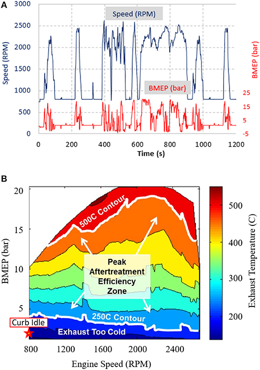
Figure 1. (A) The speed (RPM) load (BMEP) space corresponding to the engine used in this effort during the HDFTP drive cycle. (B) Thermal contour regions for the engine in this study using its stock fuel-efficient calibration. Curb idle is represented by 800 RPM and 1.3 bar BMEP.
Figure 1B illustrates the engine-out temperatures required for effective aftertreatment operation. As shown, fuel-efficient (FE) low load operation, which includes curb idle, generally does not produce engine-out temperatures that are high enough to support effective SCR NOx reduction. It will be experimentally demonstrated at curb idle that both CDA and Cylinder Cutout are capable of achieving desirable engine-out temperatures in a more fuel efficient manner than a state-of-the-art thermal calibration.
Previous work has demonstrated fuel efficiency benefits for CDA and Cylinder Cutout, where only CDA has been shown to improve fuel-efficient stay-warm aftertreatment thermal management performance. As a result, a comparison of fuel-efficient stay-warm performance between CDA and Cylinder Cutout has not been experimentally demonstrated in prior research.
The effort described here will compare Cylinder Cutout and CDA on a multi-cylinder diesel engine by establishing their fuel-efficient thermal management characteristics at curb idle and evaluating their performance against a state-of-the-art thermal calibration. Additionally, the extent to which the utilization of exhaust manifold pressure control via a VGT, the configuration of the exhaust manifold, and the placement of the EGR loop impact the thermal management performance of Cylinder Cutout and CDA is discussed in detail.
2. Experimental Setup
A six-cylinder Clean Idle Certified Cummins diesel engine equipped with a camless variable valve actuation (VVA) system was utilized to perform the experiments described in this effort. An alternating current PowerTest dynamometer is attached to the engine to enable engine speed/torque control. Figure 2A illustrates a schematic of the air handling system, which is composed of a VGT turbocharger and cooled high pressure exhaust gas recirculation (EGR). The fuel system incorporates a high pressure common rail fuel injection arrangement and the cooling system utilizes an air-to-water charge air cooler (CAC).
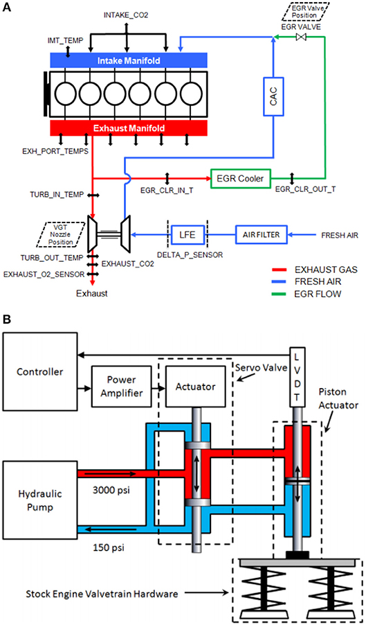
Figure 2. (A) Schematic drawing of the air handling system of the engine with the location of sensors having been labeled. (B) Schematic of the variable valve actuation setup.
A conditioned combustion air system provides fresh air flow to the engine, while a laminar flow element is incorporated for measurement. The fuel flow rate is gravimetrically measured via a Cybermetrix Cyrius Fuel Subsystem unit. Cambustion NDIR500 fast CO/CO2 analyzers measure the CO2 concentration in both the intake manifold and the exhaust pipe. The NOx at the engine-outlet condition, downstream of the turbocharger, is measured using a Cambustion CLD500 analyzer in the exhaust-pipe. AVL photo-acoustic transient analyzers record the concentration of particulate matter in the exhaust pipe. The intake and exhaust paths are lined with thermocouples and thermistors throughout the system to record real-time coolant, oil, and gas temperatures. A butterfly valve is used in the exhaust path to replicate the back-pressure that results from an in-vehicle aftertreatment system.
Each of the six cylinders are equipped with either AVL QC34C or Kistler 6067C pressure transducers, which enable measurements of in-cylinder pressure through an AVL 621 Indicom module. Crank angle reference is provided via an AVL 365C crankshaft position encoder. A dSpace data acquisition system interfaces with the experimental testbed to monitor valve-profiles, as well as log/display any necessary data. Generic serial interfaces (GSI) connect the engine control module (ECM) to the dSpace system, enabling cylinder-specific, cycle-to-cycle monitoring and control of fuel timing/amount along with additional engine operating parameters.
The fully flexible VVA system allows for cylinder independent, cycle-to-cycle control of the intake and exhaust valve opening timing, closing timing, lift, and ramp rates. Specifically, this enables complete deactivation of both intake and exhaust valves in each cylinder (i.e., CDA). Figure 2B illustrates the systems operating principle, which is powered independent of the engine via an external hydraulic pump. Linear variable differential transformers (LVDT) provide position feedback and real-time control of individual valve pairs, two per cylinder. For this study, the system controller only employs the flexibility of the VVA to implement CDA, as cylinder cutout does not require modification to the valve profiles.
3. Methodology
3.1. Individual Strategy Analysis
The following summarizes the strategies investigated in this effort:
1. Fuel Efficient (FE) Baseline
2. Thermal Management (TM) Baseline
3. Cylinder Deactivation (CDA)
(a) CDA: 1,2,3 Active
(b) CDA: 4,5,6 Active
(c) CDA: 3,4 Active
4. Cylinder Cutout
(a) Cylinder Cutout: 1,2,3 Active
(b) Cylinder Cutout: 4,5,6 Active
(c) Cylinder Cutout: 2,3,4,5 Active
Figure 3A is representative of the engine used in this study operating in conventional six cylinder mode, including the FE Baseline and TM Baseline modes. FE Baseline targets fuel efficiency, for which fuel-efficient injections are implemented to enable a heat release starting near top dead center. TM Baseline targets aftertreatment thermal management at the expense of increased fuel consumption. Specifically at curb idle, this strategy utilizes exhaust manifold pressure control, via an over-closed VGT, to increase the back-pressure and enable more fuel to be consumed for improved thermal management performance.
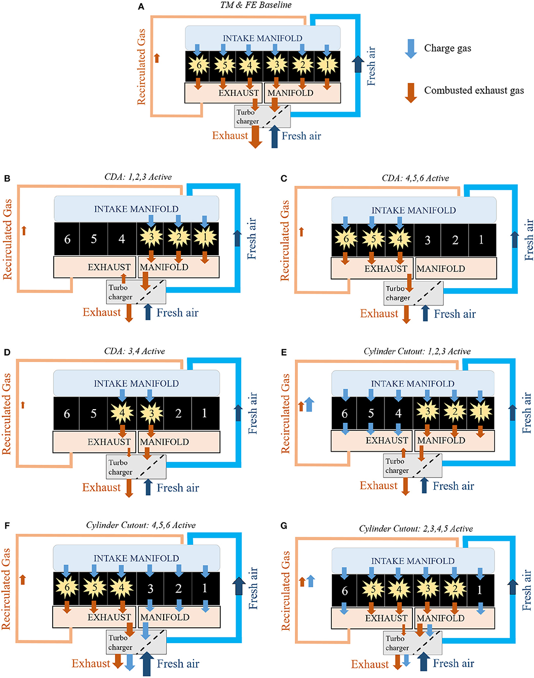
Figure 3. (A) Normal operation with the engine firing in all six cylinders. (B) Three cylinder CDA operation with the engine firing in the first three cylinders. (C) Three cylinder CDA operation with the engine firing in the last three cylinders. (D) Four cylinder CDA operation with the engine firing in the middle two cylinders. (E) Three Cylinder Cutout operation with the engine firing in the first three cylinders. (F) Three Cylinder Cutout operation with the engine firing in the last three cylinders. (G) Two Cylinder Cutout operation with the engine firing in the middle four cylinders.
CDA is implemented via deactivation of fueling and valve motions for 3 or 4 (of 6) cylinders, as shown in Figures 3B–D.
Cylinder cutout is implemented by deactivating fuel injections for 2 or 3 (of 6) cylinders, while maintaining nominal intake and exhaust valve movement in all six cylinders. As a result, the cylinders without fuel are still allowed to breathe normally, which is the key difference from CDA operation. Figures 3E–G illustrate the different Cylinder Cutout operations utilized in this study. Specifically, Cylinder Cutout: 1,2,3 Active and Cylinder Cutout: 4,5,6 Active correspond to operation when half of the engine is firing and the other half is pumping charge gas; the difference being whether it is the front half of the engine or the back half of the engine firing, per Figures 3E,F, respectively. Cylinder Cutout: 2,3,4,5 Active corresponds to operation when four of the six cylinders are firing (per Figure 3G), while the other two cylinders pump charge gas.
Figure 4 illustrates the valve profiles utilized for each of the different strategies. The conventional profiles shown in Figure 4A are representative of the valve movement in FE Baseline, TM Baseline, Cylinder Cutout, and only the active cylinders in CDA. The deactivated cylinders in CDA have the valve profiles depicted in Figure 4B.
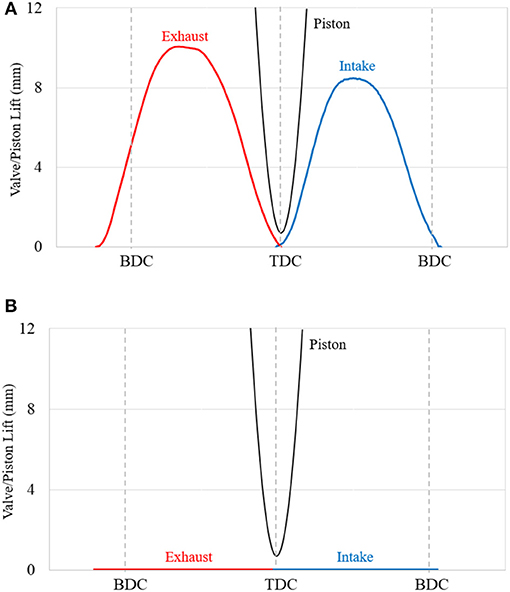
Figure 4. (A) Valve profiles for normal operation and Cylinder Cutout operation. (B) Valve profiles for the deactivated cylinders for CDA operation.
The injection timings and corresponding heat release rates for each of the aforementioned strategies are illustrated in Figure 5. FE Baseline, CDA, and Cylinder Cutout utilize a pilot and main injection (i.e., 2 injections), whereas TM Baseline implements a pilot, main, and two post injections (i.e., 4 injections). As noted previously, the FE Baseline has relatively early fuel injections to enable fuel efficient operation. Whereas, TM Baseline, CDA, and Cylinder Cutout implement late injections to increase the thermal energy at engine-out.
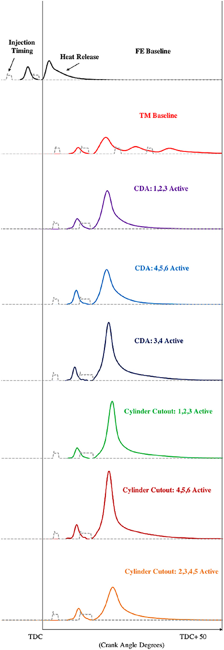
Figure 5. Heat release rates and injection timings for each strategy on a crank angle degree basis. The heat release rates are an average of the active (firing) cylinders in each strategy.
3.2. Brake Thermal Efficiency Analysis
Cycle efficiency analysis is one method used in this effort to compare the performance of each individual strategy. Each strategy has an impact on the gas exchange, energy conversion, and parasitic losses of the engine. These impacts manifest themselves in the following three cycle efficiencies: open, closed, and mechanical. Open cycle efficiency (OCE) quantifies the effectiveness of cylinder gas exchange. Closed cycle efficiency (CCE) captures the efficiency of fuel-energy conversion to piston-work during the closed cycle, and is degraded by delayed heat release and in-cylinder heat transfer. Mechanical efficiency (ME) captures the effect of friction and the parasitic losses from engine loads. Equation (1) relates these efficiencies to the brake thermal efficiency (BTE) (Stanton, 2013):
Essentially, the overall BTE of the engine can be subdivided into these three efficiencies to isolate where the relative changes are coming from. These efficiencies are derived in Stanton (2013) and obtained using measured engine pressure, volume, and load. In addition, Equation (2) shows the relationship between brake thermal efficiency (BTE) and brake specific fuel consumption (BSFC), where (LHVfuel) is the lower heating value of the fuel. Together Equations (1) and (2) provide a direct path from the cycle efficiencies to the overall BSFC.
4. Experimental Steady-State Fuel Efficient Thermal Management Results
Steady-state tests were conducted at curb idle (800 RPM and 1.3 bar BMEP) for FE Baseline, TM Baseline, and the aforementioned variations of CDA and Cylinder Cutout. Each CDA and Cylinder Cutout strategy targeted fuel-efficient thermal management performance to improve either aftertreatment warm-up or stay-warm performance. Ideal warm-up performance exhibits elevated engine-out mass flows and temperatures in order to increase the exhaust gas-to-catalyst heat transfer rate (i.e., heat up rate). Ideal stay-warm performance exhibits low engine-out mass flows and elevated temperatures to minimize/avoid catalyst-to-exhaust gas heat transfer.
The tested strategies demonstrate improvements to both the stay-warm and warm-up abilities compared to FE Baseline. In comparison to the TM Baseline, Table 1 highlights improvements in fuel-efficiency, emissions, and stay warm performance for all CDA cases, as well as Cylinder Cutout: 1,2,3 Active. However, all tested strategies exhibit an inferior warm-up performance relative to the TM Baseline (per Table 1).

Table 1. Summarized table of results at 800 RPM and 1.3 bar BMEP, comparing each strategy to the TM Baseline for stay-warm performance (at catalyst temperatures above 250°C), warm-up performance (at catalyst temperatures below 250°C), BSFC, BSNOx, BSPM, and the requirement of exhaust manifold pressure control.
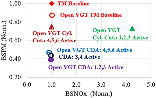
Compared to the TM Baseline, Cylinder Cutout improves aftertreatment stay-warm performance while realizing a 17% reduction in fuel consumption. CDA achieves the same stay-warm improvements while realizing a 40% reduction in fuel consumption in comparison to the TM Baseline. The split exhaust manifold architecture and the location of the EGR loop (per Figure 3), significantly impacts the performance of Cylinder Cutout operation, while only marginally influencing the performance of CDA. Additionally, the ability to directly control the exhaust manifold pressure was required for the Cylinder Cutout strategies to create the back-pressure necessary to drive enough EGR to constrain engine-out NOx and reduce airflow. Each of the Cylinder Cutout and CDA strategies exhibit emissions that were as good, or better, than the TM Baseline condition (per Figure 6). CDA allowed for a significant 65–80% reduction in PM during stay warm operation, while Cylinder Cutout allowed ~ 55% reduction in PM, compared to the TM Baseline. These reductions in PM primarily resulted from the corresponding air flow reductions for CDA and Cylinder Cutout, while maintaining relatively high air-to-fuel ratios due to reductions in fuel consumption. Reductions in engine-out NOx and HC were also observed for some of the CDA and Cylinder Cutout strategies during stay-warm operation in comparison to TM Baseline.
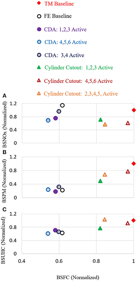
Figure 6. (A) Normalized BSNOx relative to TM Baseline. (B) Normalized BSPM relative to TM Baseline. (C) Normalized BSUHC relative to TM Baseline.
4.1. Impact on Gas Exchange Dynamics
Figure 7 shows the impact each strategy has on the charge flow, air flow, recirculated gas (RG) flow, air-to-fuel-ratio (AFR), recirculated gas mass fraction, EGR fraction, and VGT position. All flows are normalized to the charge flow of TM Baseline. As shown, FE Baseline, TM Baseline, and Cylinder Cutout have comparable charge flows because the conventional opening and closing of the intake and exhaust valves result in similar amounts of charge gas entering/exiting the six cylinders. Alternatively, CDA reduces the number of operating cylinders that induct/expel this charge gas, enabling a reduction in charge flow. Equation (3) relates the flows within the engine:
where ṁchg is the charge flow, ṁair is the air flow, and ṁRG is the RG flow.

Figure 7. (A) Charge flow through the engine normalized to the TM Baseline. (B) Air flow normalized to the charge flow TM Baseline. (C) RG flow normalized to the charge flow of TM Baseline. (D) Air-to-Fuel ratio for each of the experimental cases. (E) Recirculated gas mass fraction, corresponding to Equation (4). (F) EGR fraction, corresponding to Equation (5). (G) VGT position, in which 100% is an over-closed VGT.
The recirculated gas mass fraction represents the quotient of RG flow and charge flow (per Equation 4 from Jääskeläinen and Khair, 2016), while the EGR fraction is determined via the intake, exhaust, and ambient CO2 concentrations per Equation (5) from Domenico et al. (2017).
RG flow for conventional diesel is equivalent to EGR flow for typical operation with combustion occurring in all cylinders. These flows are also identical for CDA operation, as only the combusting cylinders contribute to the composition of the recirculated gasses. Unlike CDA and conventional six cylinder operation, Cylinder Cutout has non-firing cylinders that dilute the CO2 concentration of the recirculated gas, resulting in a difference between the RG and EGR flows. Specifically, RG flow accounts for all gas that is recirculated back to the intake manifold, which differs from the conventional EGR flow when the cutout cylinders are pumping non-combusted charge gas directly into the EGR loop, per Figure 3F.
Modern diesel engines reduce NOx using in-cylinder O2 dilution via EGR and delayed injections. In-cylinder O2 dilution achieves NOx reduction by lowering the flame front temperatures during mixing-controlled combustion in the cylinder. O2 dilution in the cylinder can be achieved by inducting a portion of already combusted exhaust gases, as the O2 mass fraction in the exhaust is lower than air, resulting from partial consumption of airborne O2 during combustion. Cylinder gases expelled into the exhaust manifold from cylinders not undergoing combustion will therefore have higher mass fractions of O2, compared to gases from the combusting cylinders. As a result, the RG from non-fired cylinders will not be as effective at diluting in-cylinder O2 levels.
Figure 7 illustrates the requirement to flow significantly higher RG (i.e., increase the recirculated gas mass fraction) for some, but not all, of the Cylinder Cutout cases to achieve desirable in-cylinder O2 mass fractions for NOx control. The amount of RG required for these cases directly depends on the location of the EGR loop, as well as which cylinders are firing. Per Figure 3, the EGR loop is located directly in line with the bank of cylinders 4, 5, and 6. This contributes to the difference in results between Cylinder Cutout: 1,2,3 Active and Cylinder Cutout: 4,5,6 Active. Specifically, implementing Cylinder Cutout: 1,2,3 Active requires a 56% increase to the RG flow in order to recirculate enough exhaust gas from cylinders 1, 2, and 3, as shown in Figure 7. For this case the EGR loop is diluted with charge gas from the bank of cutout cylinders 4, 5, and 6, thereby requiring a larger RG flow to mitigate emissions. This phenomena is also illustrated in Figures 7E,F, in which the 27% increase in the recirculated gas mass fraction for Cylinder Cutout: 1,2,3 Active enabled an EGR fraction capable of constraining NOx. The elevated RG flow was achieved using an elevated exhaust manifold pressure to drive high amounts of RG via the EGR system, resulting in a 52% reduction in air flow relative to the TM Baseline.
Cylinder Cutout: 4,5,6 Active required less RG flow because the bank of firing cylinders 4, 5, and 6 is directly feeding concentrated exhaust gas into the EGR loop. This resulted in RG flow, and therefore air flow, similar to TM Baseline. Among the three cases, Cylinder Cutout 2,3,4,5 is a more symmetric strategy in that the split exhaust manifold no longer contains one bank of cylinders emitting significantly more concentrated exhaust gas than the other. As a result, this strategy lies in-between the other two strategies by requiring less RG flow than Cylinder Cutout: 1,2,3 Active but more than Cylinder Cutout: 4,5,6 Active.
The location of the EGR loop does not induce the same discrepancy in results between CDA strategies. This is because the deactivated cylinders are not pumping charge gas from the intake to exhaust manifolds via the cylinder, thereby preventing any dilution of the recirculated exhaust gas from occurring. The CDA strategies result in less charge flow, and as a result lower air flow, than six cylinder operation because fewer cylinders are transmitting charge gas from the intake to exhaust manifold. Specifically, CDA: 1,2,3 Active, CDA: 4,5,6 Active, and CDA: 3,4 Active enable approximately ~ 46% reduction in air flow relative to the TM Baseline. Figure 7 illustrates similar bulk air, RG, and charge gas exchange for all arrangements of CDA. CDA operates without requiring exhaust manifold pressure control (unlike the TM Baseline and the Cylinder Cutout strategies), as a result of needing less EGR to constrain NOx.
4.2. Impact on Efficiency
Figure 8A illustrates the delta pressure between the exhaust and intake manifold for each strategy. In general, an increase in manifold delta pressure forces the engine to work harder at pumping gas through the cylinders. As a result, the fuel consumption monotonically increases with delta pressure, where the TM Baseline is expending the most fuel by forcing the engine to work the hardest against a significant pressure gradient.
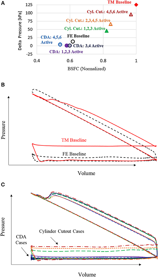
Figure 8. (A) Delta pressures between the exhaust and intake manifolds for each of the tested strategies. (B) LogP-LogV representation of the firing cylinders in the FE Baseline and TM Baseline operation. (C) LogP-LogV representation of the firing cylinders in CDA and Cylinder Cutout operation.
This phenomenon is also captured in the log-p log-v diagram (per Figures 8B,C). As shown, the TM Baseline has a significantly larger pumping loop than the efficient FE Baseline strategy (per Figure 8B). This difference is due to a large manifold delta pressure created from an over-closed VGT for the TM Baseline strategy, implemented to make the engine work harder, increasing the amount of required fueling, with higher exhaust temperatures resulting.
Figure 8C illustrates that the Cylinder Cutout strategies possess larger pumping loops than the more fuel efficient CDA. This results from a combination of an over-closed VGT and higher charge flows in the Cylinder Cutout strategies, which lead to higher pressures in the exhaust manifold. Specifically, Cylinder Cutout reduces the air flow rate via elevated amounts of recirculated gases by non-fired cylinders, which maintains elevated charge flow rates that contribute to larger delta pressures across the engine and consequently more pumping work than CDA. This leads to a less efficient Cylinder Cutout strategy in comparison to the CDA strategy. Conversely, CDA reduces the air flow rate by deactivating cylinders, which reduces the charge flow rate and enables a small delta pressure across the engine, resulting in less pumping work by the activated cylinders. The pressure-volume plots are in agreement with the pressure difference between the intake and exhaust manifolds in Figure 8A, as a larger delta pressure results in a larger pumping loop.
Open, closed, and mechanical cycle efficiencies are used to understand the BTE and fuel economy impact for each strategy (per Figure 9). As shown, the tested strategies exhibited comparable CCE and ME, indicating similar fuel-energy to piston-work conversion and parasitic losses, respectively. Therefore, the main contributor to the differences in fuel efficiency and BTE is OCE. Specifically, due to the reduction in air flow and the low delta pressures across the manifolds, CDA strategies realize the highest OCE, with a ~ 50% relative improvement over the TM Baseline. Among the Cylinder Cutout strategies, Cylinder Cutout: 1,2,3 Active shows the largest absolute improvement of nearly 17% over the TM Baseline. These OCE improvements are less significant for Cylinder Cutout due to elevated charge flows and higher exhaust manifold pressures (i.e., more pumping work) in comparison to CDA. Overall, these efficiency impacts correspond to 40–45% improvement in fuel efficiency for the CDA strategies and 3–17% improvement in fuel efficiency for the Cylinder Cutout strategies relative to the TM Baseline (per Figure 9D). In comparison to the FE Baseline, this corresponds to ~ 3−12% increase in fuel efficiency for CDA, and ~ 33 − 57% decrease in fuel efficiency for Cylinder Cutout.
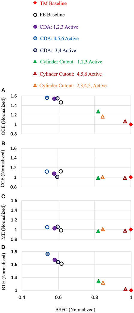
Figure 9. (A) Represents the impact each strategy had on OCE. (B) Represents the impact each strategy had on CCE. (C) Represents the impact each strategy had on ME. (D) Represents the impact each strategy had on the overall BTE.
4.3. Impact on Aftertreatment Thermal Management
Figure 10 illustrates the steady-state exhaust flow, turbine outlet temperature (TOT), and BSFC for the tested strategies. As shown, all CDA cases and Cylinder Cutout: 1,2,3 Active have approximately ~ 50% less exhaust flow in comparison to the TM Baseline. These low exhaust flows are directly related to the aforementioned air flow reductions. Furthermore, CDA: 3,4 Active and Cylinder Cutout: 1,2,3 Active have TOT values within 3°C of the TM Baseline. The remaining Cylinder Cutout and CDA strategies realize nearly ~ 37°C reduction in TOT compared to the TM Baseline, while Cylinder Cutout: 4,5,6 Active is the only strategy with a comparable exhaust flow (~ 5% reduction). Figure 10 also shows CDA's ability to achieve elevated TOTs while consuming less fuel than the Cylinder Cutout strategies.
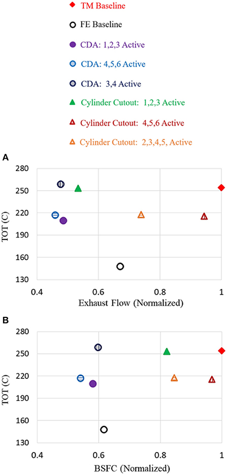
Figure 10. (A) Represents TOT and exhaust flow for each strategy. (B) Represents TOT and BSFC for each strategy. Elevated TOT and exhaust flows are ideal for warm-up; whereas low exhaust flows and BSFC are key for stay-warm.
The thermal performance of each strategy is compared from a warm-up and stay-warm standpoint. Specifically, warm-up requires exhaust gas-to-catalyst heat transfer, which is enabled by elevated exhaust flow rates and engine-outlet temperatures larger than the current catalyst temperature. Stay-warm operation requires elevated engine-outlet temperatures to either eliminate, or minimize, catalyst-to-exhaust gas heat transfer. Figure 11 represents an approximation of the relative heat transfer rate from the engine-out gas to the aftertreatment system components. This heat transfer rate is derived from the Dittus-Boelter empirical equation and approximated by the following:
where is the heat rate, Cp is the heat capacity, ṁexh is the exhaust flow, Tcatalyst is the catalyst temperature, and TOT is the turbine outlet temperature.
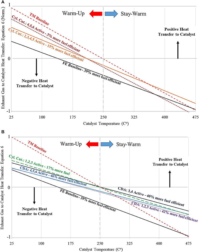
Figure 11. Heat transfer rate plots, where the exhaust flow corresponds to the steepness of the slope and the crossing of the zero heat transfer rate axis represents the TOT. (A) Warm-up heat transfer rates require higher exhaust flows (i.e., steeper slopes) and generally high TOTs. (B) Stay-Warm heat transfer rates require lower exhaust flows (i.e., gradual slopes) and generally high TOTs.
This simplified model characterizes an approximate heat transfer rate to the aftertreatment system from the engine exhaust gas, in which experimental ṁexh and TOT are obtained for each of the curb idle strategies. This equation shows that there is a positive heat transfer rate to the aftertreatment system so long as (TOT − Tcatalyst) > 0, thus resulting in warm-up. Likewise, if (TOT − Tcatalyst) < 0, the aftertreatment system cools down due to a negative heat transfer rate. The crossing point of the zero heat transfer lines in Figure 11 correspond to the TOT for the given strategy. The exhaust flow in Equation (6) correlates to the slope of the normalize heat transfer lines in Figure 6. Higher exhaust flows result in steeper slopes in the heat transfer line, while lower exhaust flows result in gradual slopes. Effectively, high exhaust flow rates can lead to an improved warm-up rate if TOT is larger than Tcatalyst. Conversely, if TOT is smaller than Tcatalyst, that same high exhaust flow rate will lead to faster cooling of the aftertreatment system. When considering low exhaust flow rates, the impact of TOTs lower than desirable/current catalyst temperatures can be partly mitigated. Low exhaust flow rates reduce the magnitude of heat transfer during operating modes when engine-outlet temperatures drop below desirable catalysts temperatures.
Figures 11A,B show that for aftertreatment catalyst temperatures below 250°C, the TM Baseline is the fastest warm-up strategy of those methods considered in this paper. Cylinder Cutout: 4,5,6 Active is the next best warm-up performer. Despite having a comparable exhaust flow to TM Baseline (i.e., similar slopes), this Cylinder Cutout strategy underperforms due to its lower TOT.
Figure 11B shows that for aftertreatment catalyst temperatures above 250°C, CDA: 3,4 Active and Cylinder Cutout: 1,2,3 Active outperform TM Baseline. This is due to lower fuel consumption, together with TOTs comparable to TM Baseline, and exhaust flow rates lower than TM Baseline. More specifically, these CDA and Cylinder Cutout strategies reduce fuel consumption by 40 and 17%, respectively, in comparison to TM Baseline.
Figure 11B illustrates approximately ~53 and 45% improvements to the heat transfer rate for CDA: 3,4 Active and Cylinder Cutout: 1,2,3 Active respectively, for catalyst temperatures above 250°C. CDA: 1,2,3 Active and CDA: 4,5,6 Active perform similarly to each other, in which both exhibit approximately a 10% reduction in the heat transfer rate relative to CDA: 3,4 Active for all catalyst temperatures. This is due to a reduction in TOT while maintaining a similar exhaust flow (i.e., similar slopes).
In summary, the TM Baseline is the fastest curb idle warm-up strategy considered in this paper due to an elevated exhaust flow and TOT. CDA: 3,4 Active and Cylinder Cutout:1,2,3 Active outperform the other curb idle strategies from a stay-warm perspective. CDA: 3,4 Active is also more efficient in its stay-warm thermal management performance as it realizes a 40% reduction in fuel compared to the TM baseline; whereas Cylinder Cutout:1,2,3 Active realizes a 17% reduction in fuel.
5. Experimental Steady-State Results Without Exhaust Manifold Pressure Control
As demonstrated in the previous section, CDA did not utilize exhaust manifold pressure control to improve the stay-warm performance compared to TM Baseline. However, the previous Cylinder Cutout strategies utilized exhaust manifold pressure control to create the necessary back-pressure for aftertreatment thermal management, air flow reduction, and RG flow control, in which only Cylinder Cutout: 1,2,3 Active improved the stay-warm performance relative to TM Baseline. As a result, this section will demonstrate the extent to which the tested strategies depend on exhaust manifold pressure control for fuel efficient stay-warm performance and NOx control. Specifically, per Figure 12, an Open VGT setting is employed to eliminate the ability to control the exhaust manifold pressure (i.e., reduce the back-pressure on the engine) for all CDA and Cylinder Cutout strategies.
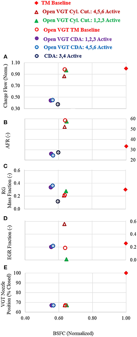
Figure 12. (A) Charge flow through the engine normalized to the TM Baseline. (B) Air-to-Fuel ratio for each of the experimental cases. (C) Recirculated gas mass fraction, corresponding to Equation (4). (D) EGR fraction, corresponding to Equation (5). (E) VGT position, in which 100% is an over-closed VGT.
Figure 12 illustrates the gas exchange for each strategy when implementing the Open VGT setting. The Open VGT TM Baseline illustrates the effect of opening the VGT position nearly 33% from its stock position in the TM Baseline strategy (per Figure 7G). As a result, a 37% improvement in fuel efficiency was realized due to the significant reduction in back-pressure, and therefore pumping work. The reduction in fuel significantly increased the AFR, which prompted a ~ 75°C reduction in TOT (per Figures 13A,B), and a ~ 30 − 50% reduction in exhaust gas-to-catalyst heat transfer (per Figure 13C).
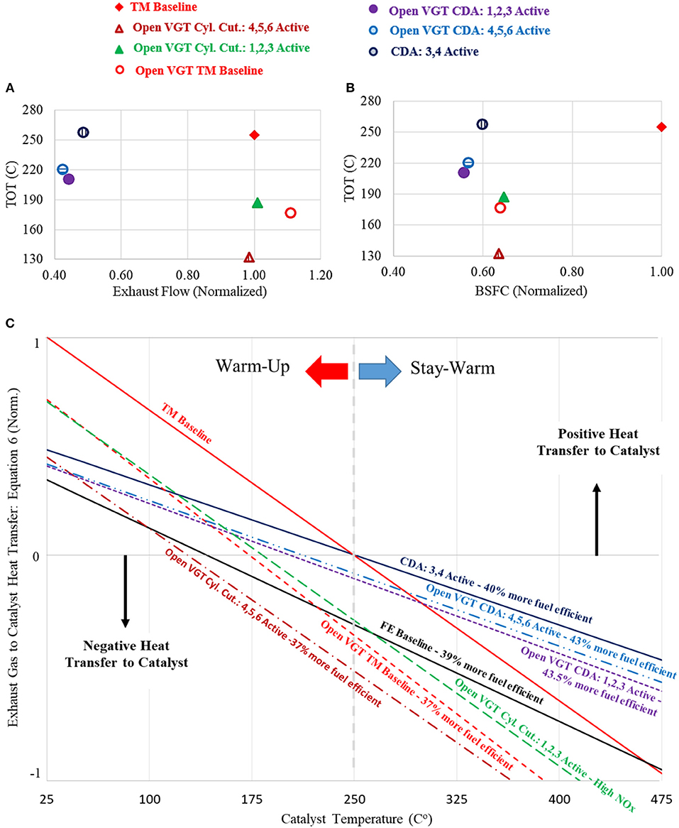
Figure 13. (A) TOT and exhaust flow for each strategy tested with an open VGT setting. Elevated TOT and exhaust flows are ideal for warm-up; whereas low exhaust flows and BSFC are key for stay-warm. (B) TOT and BSFC for each strategy tested with an open VGT setting. (C) Heat transfer rate plots for the open VGT strategies, where the exhaust flow corresponds to the steepness of the slope and the crossing of the zero heat transfer rate axis represents the TOT.
Both open VGT Cylinder Cutout strategies illustrate nearly a ~ 37% reduction in fuel consumption compared to the TM Baseline. As mentioned previously, the Cylinder Cutout strategies are directly impacted by the location of the EGR loop. Firing cylinders 4, 5, and 6 with an open VGT resulted in nearly a 170°C reduction in TOT, leading to a significant decrease in thermal management performance relative to the TM Baseline (per Figure 13C). This reduction in temperature is a result of pumping cold gasses to the exhaust via the cutout cylinders, as well as elevated AFR values. Conversely, Open VGT Cylinder Cutout: 1,2,3 Active failed to constrain BSNOx (per Figure 14), due to a relatively low EGR fraction (per Figure 12). Without exhaust manifold pressure control, this strategy was unable to create the necessary back-pressure to drive enough recirculated exhaust gas from cylinders 1, 2, and 3. As a result, the RG was primarily composed of gasses from cylinders not undergoing combustion (i.e., high O2 concentrations), leading to a low EGR fraction and a high BSNOx level.
The CDA strategies realized a 40% reduction in fuel consumption when deactivating four cylinders and ~ 43% reduction in fuel when deactivating three cylinders (per Figure 12). CDA: 3,4 Active is identical to the strategy in the previous section due to the fact that it already utilized the Open VGT setting. As a result, it maintains the fuel efficient thermal management performance via an elevated TOT and low exhaust flow rate (per Figures 13A,C). Similarly, deactivating three cylinders and enforcing an open VGT position did not significantly impact the fuel efficient thermal management performance.
In summary, the Cylinder Cutout strategies were not capable of achieving the necessary back-pressure on the engine without directly manipulating the exhaust manifold pressure, resulting in poor thermal management performance and inconsistent NOx control (per Figures 13C, 14), respectively. Conversely, CDA operation did not require exhaust manifold pressure control to drive EGR for NOx control. Therefore, CDA maintained the improved fuel efficient stay warm performance without requiring an elevated back-pressure on the engine.
6. Summary
Aftertreatment systems require thermal energy to operate efficiently and effectively. The efforts in this paper demonstrate at a curb idle condition (800 RPM and 1.3 bar BMEP) that both CDA and Cylinder Cutout are effective strategies at preserving heat to maintain efficient aftertreatment performance. Implementing Cylinder Cutout on a diesel engine requires deactivating only fuel injections for a sub-set of cylinders, whereas CDA requires deactivating fuel injections and valve motions.
In comparison to a state-of-the-art six cylinder thermal management baseline (TM Baseline) calibration with four late injections and an elevated exhaust manifold pressure, Cylinder Cutout realizes 17% fuel savings while more effectively keeping an already warm aftertreatment system warm enough to operate efficiently. Specifically at curb idle, Cylinder Cutout: 1,2,3 Active realizes a high TOT and a low exhaust flow rate via elevated amounts of recirculated gases by non-fired cylinders, which enables a slower cool down rate of the aftertreatment system in comparison to conventional TM Baseline. These elevated amounts of recirculated exhaust gas required high exhaust manifold pressures to drive the flow. Overall, this strategy corresponded to nearly a 45% improvement in exhaust gas-to-catalyst heat transfer for catalyst temperatures above ~ 250°C.
It was also demonstrated that Cylinder Cutout thermal management performance was significantly dependent on the geometry of the split exhaust manifold and the ability to control the exhaust manifold pressure. Specifically, the location of the EGR loop on the tested split manifold resulted in instances with either diluted or concentrated recirculated gas due to the Cylinder Cutout cases effectively pumping non-combusted charge gas through the cutout cylinders. As a result, this architecture of the engine led both Cylinder Cutout: 4,5,6 Active and Cylinder Cutout: 2,3,4,5 Active to under-perform the TM Baseline at warming up the aftertreatment system, as well as keeping it warm during curb idle operation.
In comparison to conventional TM Baseline, CDA: 3,4 Active was experimentally demonstrated to achieve a 40% reduction in fuel savings, while enabling a high TOT and low exhaust flow rate via reduced charge flow to improve the ability to preserve efficient aftertreatment operation. This corresponded to nearly a 53% improvement to the exhaust gas-to-catalyst heat transfer rate for catalyst temperatures above ~ 250°C. Unlike the Cylinder Cutout cases, the geometry of the exhaust manifold did not significantly impact the performance of CDA, as both CDA: 1,2,3 Active and CDA: 4,5,6 Active proved to be viable candidates at fuel-efficiently maintaining the thermal energy in the aftertreatment system. It should also be noted that these strategies do not require exhaust manifold pressure control to increase the back-pressure for thermal management or EGR delivery control.
Cylinder Cutout and CDA strategies were shown to improve upon the conventional TM Baseline stay-warm operation by achieving comparable exhaust heat rates to the aftertreatment system, thereby resulting in similar thermal management performance. Both strategies demonstrated open cycle efficiency improvements via reductions in air flow through the engine. For the same thermal management improvement at curb idle, CDA allows an additional 23% fuel savings over Cylinder Cutout.
Data Availability
The datasets generated for this study will not be made publicly available, Confidential.
Author Contributions
KV: spear headed experimental work, analysis, and paper development. GS: student mentoring and thought leadership. AR: assisted with experimental work and analysis. JM: provide industry perspective, discussed results.
Funding
The authors declare that this study received funding from Eaton and Cummins. The funders had the following involvement with the study: discussion of results and ideation for work tasks. Eaton and Cummins individuals had no role in data collection and analysis, decision to publish, or preparation of the manuscript (other than to proofread).
Conflict of Interest Statement
JM is employed by company Eaton.
The remaining authors declare that the research was conducted in the absence of any commercial or financial relationships that could be construed as a potential conflict of interest.
Acknowledgments
Experiments were performed in Ray W. Herrick laboratories at Purdue University. The engine was provided by Cummins Inc. Technical assistance was also provided by the project's sponsors: Cummins Inc. and Eaton. The authors would like to thank Ryan Thayer and John Foster for the support they extended toward this work.
References
Archer, A., and McCarthy, J. Jr. (2018). Quantification of Diesel Engine Vibration Using Cylinder Deactivation for Exhaust Temperature Management and Recipe for Implementation in Commercial Vehicles. SAE Technical Paper 2018-01-1284, SAE International.
Charlton, S., Dollmeyer, T., and Grana, T. (2010). Meeting the US heavy-duty EPA 2010 standards and providing increased value for the customer. SAE Int. J. Commer. Veh. 3, 101–110. doi: 10.4271/2010-01-1934
Chen, P., and Wang, J. (2014). Control-oriented model for integrated diesel engine and aftertreatment systems thermal management. Control Eng. Pract. 22, 81–93. doi: 10.1016/j.conengprac.2013.09.009
Chen, P., and Wang, J. (2016). Estimation and adaptive nonlinear model predictive control of selective catalytic reduction systems in automotive applications. J. Process Control 40, 78–92. doi: 10.1016/j.jprocont.2016.01.005
Ding, C., Roberts, L., Fain, D. J., Ramesh, A. K., Shaver, G. M., McCarthy, J., et al. (2015). Fuel efficient exhaust thermal management for compression ignition engines during idle via cylinder deactivation and flexible valve actuation. Int. J. Engine Res. 17, 619–630. doi: 10.1177/1468087415597413
Domenico, D. S., Oliveira, A. d., and Sodre, J. R. (2017). Effects of egr rate on performance and emissions of a diesel power generator fueled by B7. J. Braz. Soc. Mech. Sci. Eng. 39, 1919–1927. doi: 10.1007/s40430-017-0777-x
Garg, A., Magee, M., Ding, C., Roberts, L., Shaver, G., Koeberlein, E., et al. (2016). Fuel-efficient exhaust thermal management using cylinder throttling via intake valve closing timing modulation. Proc. Instit. Mech. Eng. Part D 230, 470–478. doi: 10.1177/0954407015586896
Gehrke, S., Kovács, D., Eilts, P., Rempel, A., and Eckert, P. (2013). Investigation of VVA-based exhaust management strategies by means of a HD single cylinder research engine and rapid prototyping systems. SAE Int. J. Commer. Veh. 6, 47–61. doi: 10.4271/2013-01-0587
Jääskeläinen, H., and Khair, M. K. (2016). DieselNet. Available online at: https://www.dieselnet.com/tech/engine_egr.php (accessed September 16, 2018).
Hou, X., Ma, Y., Peng, F., Yan, F., and Zhang, X. (2010). “Research on temperature characteristics of dpf regeneration technology based on catalytic combustion of fuel injection,” in Power and Energy Engineering Conference (APPEEC), 2010 Asia-Pacific (Chengdu: IEEE), 1–4.
Johnson, T. V. (2012). Vehicular emissions in review. SAE Int. J. Engines 5, 216–234. doi: 10.4271/2016-01-0919
Joshi, M. C., Gosala, J. B., Allen, C. M., Vos, K., Voorhis, M. V., and Taylor, A. (2017). Reducing diesel engine drive cycle fuel consumption through use of cylinder deactivation to maintain aftertreatment component temperature during idle low load operating conditions. Front. Mech. Eng. 3:8. doi: 10.3389/fmech.2017.00008.
Konrad, J., Lauer, T., Moser, M., Lockner, E., and Zhu, J. (2018). Engine Efficiency Optimization Under Consideration of NOx- and Knock-Limits for Medium Speed Dual Fuel Engines in Cylinder Cut-Out Operation. SAE Technical Paper 2018-01-1151, SAE International.
Leone, T. G., and Pozar, M. (2001). Fuel economy benefit of cylinder deactivation sensitivity to vehicle application and operating constraints. SAE Tech. Pap. Ser. 1645, 10–11. doi: 10.4271/2001-01-3591
Lu, X., Ding, C., Ramesh, A., Shaver, G., Holloway, E., McCarthy, J., et al. (2015). Impact of cylinder deactivation on active diesel particulate filter regeneration at highway cruise conditions. Front. Mech. Eng. 1:9. doi: 10.3389/fmech.2015.00009
Mo, H., Huang, Y., Mao, X., and Zhuo, B. (2013). The effect of cylinder deactivation on the performance of a diesel engine. Proc. Instit. Mech. Eng. Part D. 228, 199–205. doi: 10.1177/0954407013503627
Radulescu, A., McCarthy, J. R. Jr., and Brownell, S. (2013). Development of a Switching Roller Finger Follower for Cylinder Deactivation in Gasoline Engine Applications. SAE Technical Paper 2016-01-0589, SAE International.
Ramesh, A., Shaver, G., Allen, C., Gosala, D., Nayyar, S., Caicedo, D., et al. (2017). Utilizing low airflow strategies, including cylinder deactivation, to improve fuel efficiency and aftertreatment thermal management. Int. J. Engine Res. 18, 1005–1016. doi: 10.1177/1468087417695897
Song, X., Surenahalli, H., Naber, J., Parker, G., and Johnson, J. H. (2013). Experimental and Modeling Study of a Diesel Oxidation Catalyst (DOC) Under Transient and CPF Active Regeneration Conditions. SAE Technical Paper, SAE International.
Stadlbauer, S., Waschl, H., Schilling, A., and del Re, L. (2013). DOC Temperature Control for Low Temperature Operating Ranges With Post and Main Injection Actuation. Technical report, SAE Technical Paper, SAE International.
Stanton, D. W. (2013). Systematic Development of Highly Efficient and Clean Engines to Meet Future Commercial Vehicle Greenhouse Gas Regulations. L. Ray Buckendale Lecture 2013-01-2421 2013.
United States Environmental Protection Agency (2010). Heavy-Duty Highway Compression-Ignition Engines and Urban Buses: Exhaust Emission Standards.
Yang, J., Quan, L., and Yang, Y. (2012). Excavator energy-saving efficiency based on diesel engine cylinder deactivation technology. Chin. J. Mech. Eng. 25, 897–904. doi: 10.3901/CJME.2012.05.897
Zammit, J.-P., McGhee, M. J., Shayler, P. J., and Pegg, I. (2014). The influence of cylinder deactivation on the emissions and fuel economy of a four-cylinder direct-injection diesel engine. Proc. Instit. Mech. Eng. Part D 228, 206–217. doi: 10.1177/0954407013506182
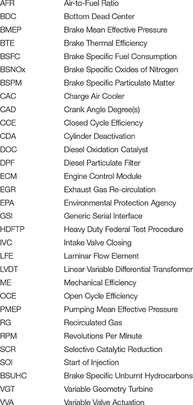
Nomenclature
Keywords: variable valve actuation, cylinder deactivation, cylinder cutout, gas exchange, fuel efficiency, aftertreatment thermal management
Citation: Vos KR, Shaver GM, Ramesh AK and McCarthy J Jr (2019) Impact of Cylinder Deactivation and Cylinder Cutout via Flexible Valve Actuation on Fuel Efficient Aftertreatment Thermal Management at Curb Idle. Front. Mech. Eng. 5:52. doi: 10.3389/fmech.2019.00052
Received: 19 May 2019; Accepted: 05 August 2019;
Published: 21 August 2019.
Edited by:
Ming Jia, Dalian University of Technology (DUT), ChinaReviewed by:
Matt Hall, University of Texas at Austin, United StatesYaopeng Li, Dalian University of Technology (DUT), China
Copyright © 2019 Vos, Shaver, Ramesh and McCarthy. This is an open-access article distributed under the terms of the Creative Commons Attribution License (CC BY). The use, distribution or reproduction in other forums is permitted, provided the original author(s) and the copyright owner(s) are credited and that the original publication in this journal is cited, in accordance with accepted academic practice. No use, distribution or reproduction is permitted which does not comply with these terms.
*Correspondence: Gregory M. Shaver, Z3NoYXZlckBwdXJkdWUuZWR1
 Kalen R. Vos
 Gregory M. Shaver
 Aswin K. Ramesh
 James McCarthy Jr.