- Ishlinsky Institute for Problems in Mechanics of RAS (IPMech RAS), Russian Academy of Sciences, Moscow, Russia
Sliding contact of a smooth indenter and a two-layered half-space is considered to take rheological properties of materials into account. A viscoelastic layer bonded with a rigid half-space is analyzed as well as the opposite viscoelastic half-space covered by a rigid layer. The problem is formulated as quasi-static. A numerical-analytical method of solution is based on a boundary element method and an iteration procedure. A new analytical solution is used to calculate the influence of coefficients for the computation procedure. Contact pressure, energy dissipation and internal stresses are analyzed depending on sliding velocity, layer thickness and Poisson's ratio.
Introduction
Rubbers and other polymers are often used as coatings to provide damping, anti-noise and other effects during friction. In many cases the materials are much more compliant than the substrates. A friction interaction of such coatings can be considered when using the model of the viscoelastic layer bonded to a rigid half-space.
A one-dimensional model of the viscoelastic layer is widely used for a 3-D contact problem solution, for example, in Klüppel and Heinrich (2000), Persson (2001), Morozov and Makhovskaya (2007), Lyubicheva (2008), Goryacheva et al. (2014), and Soldatenkov (2015). It allows not only to obtain an analytical solution but also to consider the additional effects such as an adhesive interaction of surfaces (Goryacheva et al., 2014) or multiple contact (Klüppel and Heinrich, 2000; Persson, 2001; Lyubicheva, 2008; Soldatenkov, 2015).
2-D contact problems for a layer with rheological properties and constant Poisson ratio have been formulated and solved in Mark (2008) and Aleksandrov and Mark (2009); the contact pressure and sliding resistance, caused by energy dissipation, is analyzed based on the solutions.
3-D quasi-static contact problems for indenters sliding over a viscoelastic half-space were developed in Aleksandrov et al. (2010), Goryacheva et al. (2015, 2016), Koumi et al. (2015), Stepanov and Torskaya (2016). Contact problems considering the material model specified by a spectrum of relaxation times are considered in Aleksandrov et al. (2010). The effect of the adhesive friction component on energy dissipation was analyzed in Goryacheva et al. (2015, 2016). A viscoelastic material with an inclusion was considered in Koumi et al. (2015). The contact problem solution can be used to calculate and analyze internal stresses in viscoelastic material (Stepanov and Torskaya, 2016). The method developed for the viscoelastic half-space was also used to construct an approximation for the viscoelastic layer (Menga et al., 2016).
For the case of coated viscoelastic materials, we could not find analytical or semi-analytical models that calculate the pressure distribution and energy dissipation in sliding contact. Relatively hard coatings are used to improve friction and wear resistance of rubbers (Bai et al., 2018) or to protect the materials from chemical degradation.
In this paper, a quasi-static problem solution for a smooth indenter sliding over a linear-viscoelastic layer (or viscoelastic half-space covered by a rigid coating) is based on the development of classical methods for layered structures. The analysis of stresses is a relevant task, which is important to predict the fatigue wear and material fracture.
Problem Formulation
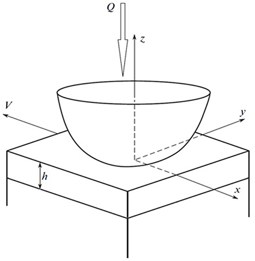
Let us consider a contact problem for a rigid smooth slider and a layer with thickness h bonded with a half-space. Indenter slides with a constant velocity V along the Ox axis; loaded with vertical force Q (Figure 1). An origin of coordinate system (x,y,z) is placed at the center of the indenter, the Oz axis is directed normally to the unloaded surface of the layer. The origin of the coordinate system is located at the point of initial layer-indenter contact.
The following boundary conditions are considered at the surface (z = 0):
Here Ω is the contact zone, w(x,y) is the vertical displacement of the upper layer boundary, D – is the indentation depth of the indenter, σz, τxz, τyz are normal and tangential stresses. The shape of the indenter is specified by a smooth function f(x,y).
Contact pressure p(x, y) = −σz(x, y) and contact area are to be found. The equilibrium condition is as follows:
We also used the condition of zero normal stresses at the boundary of the contact zones.
Conditions at the layer-substrate interface (z = −h) satisfy the case of perfect adhesion. For the case of a rigid plate, which bends on the viscoelastic substrate, we have equal boundary displacements:
Here ux and uy are tangential displacements. Indexes (1) and (2) correspond to the layer and the substrate, respectively. For the case of the rigid substrate, condition (3) transforms to the following
Viscoelastic material is used as a coating or as a substrate in combination with essentially more hard material, which can be modeled as a rigid half-space or as a plate with flexural stiffness. Mechanical properties of linear viscoelastic material are defined by the following stress-strain relations (Goryacheva et al., 2015):
Here ν is Poisson's ratio, E and G are Young's modulus and shear modulus, respectively. The creep kernel is an exponential function which depends on relaxation time 1/k and retardation time ω.
Method of Solution
First let us consider a load distributed uniformly within the square with side 2a, which moves over the viscoelastic layer. Conditions at the surface are as follows:
In the case of a layered elastic half-space, the problem of determining stresses and displacements is solved using methods based on double integral Fourier transforms (Nikishin and Shapiro, 1970).
It is shown that the normal displacements of the upper layer boundary are determined by the following expression:
Here x′, y′, w′ are dimensionless coordinates and normal displacements of the surface related to the half-side a of the square, χ = E1(1 + ν2)/E2(1 + ν1), γ, φ are the coordinates in the space of the double integral Fourier transforms, λ = h/a is a dimensionless thickness of the layer, Δ(γ, φ, λ, χ) is obtained during solution of the system of linear functional equations, derived from boundary conditions (1–3) using the biharmonic functions for the definition of the stresses and displacements. An expression that defines the Δ(γ, φ, λ, χ) is very complex (Nikishin and Shapiro, 1970), but in the case of a layer bonded with a rigid half-space (χ = 0) it is simplified as follows:
Here is the result of an application of the double integral Fourier transforms to the pressure distribution given by Equation (6).
For the case of a rigid plate, which is bonded to an elastic half-space (χ = ∞), it is also possible to derive Δ(γ, φ, λ), though the expression would be more cumbersome than (8).
The case of the distributed load moving with constant velocity over a viscoelastic half-space was considered in Aleksandrov and Goryacheva (2005) with the assumption that the shear modulus is a time-dependent operator and the Poisson ratio is a constant. Following (Aleksandrov and Goryacheva, 2005) we obtained normal displacements of the surface of the viscoelastic layer from (7) in the coordinate system, related to the center of the square containing the distributed load:
here K(t) is the creep kernel (5), V′ is the sliding velocity divided by a (V′ = V/a), G is the instantaneous shear modulus.
For the exponential creep kernel introduced in Equation (5), the time integral in Equation (9) can be analytically calculated. As a result, we obtain the following relation:
Here c = k·ω. Due to constant pressure q appearing linearly in function Δ(γ, φ, λ), (10) may be used to calculate the influence of coefficients in the boundary elements method, when contact pressure p(x,y) is obtained as a piecewise function.
Expressions (1) and (2) lead to the following system of linear equations:
where p1…pN are unknown constant pressures in each of the N elements, values f1…fN are defined by the indenter shape. Coefficients are obtained from (10):
Here is a distance between square elements, Δ′(γ, φ, λ) = Δ(γ, φ, λ)/q. For the first step of the iteration procedure we chose a contact area, which is known to be larger than the actual one. For this area solution, Equation (11) contains some elements with negative pressure. In the next step of iteration, the values of negative elements are set to null and therefore the value of N decreases. As a result of the iteration procedure, we obtained the contact pressure distribution p(x,y) and the contact area Ω.
Contact pressure distributions are used to calculate internal stresses in the viscoelastic layer or substrate. Expressions for such calculations were obtained for elastic layered half-space by (Nikishin and Shapiro, 1970):
As the presented expressions (13) depend only on the Poisson ratio, they may be used to calculate the internal stresses in the viscoelastic material, which is characterized by a constant Poisson ratio.
Results
The method described above, was used to consider a sliding contact of a spherical indenter (with radius R) and a layered half-space with the viscoelastic material used as a layer or as a substrate. The following dimensionless parameters were used for analysis: dimensionless coordinates (x*, y*) = (x, y)/R, velocity V* = Vω/R = V′ω·a/R, layer thickness h* = h/R, load (here Gl is longitudinal shear modulus) and contact pressure .
Viscoelastic Layer and Rigid Substrate
Figure 2 presents the contact pressure distribution for two values of the velocity: V* = 1/3 (Figure 2A) and V* = 10 (Figure 2B). The first case corresponds to sufficient asymmetry, which is caused by the rheological properties of the material. Therefore, a force M* that is opposite to the sliding direction arises. It is the deformation component of the friction force (or sliding resistance). Problems under consideration are without tangential stresses at the surface, and the friction coefficient is defined as follows (Goryacheva et al., 2016):
Together with an increase of sliding velocity (Figure 2B), the size of the contact area decreases, and the maximum value of the contact pressure increases; and the pressure distribution becomes almost symmetrical. Similar phenomenon was observed earlier for 1-D models of viscoelastic layer bonded with a rigid half-space (Lyubicheva, 2008), and also for viscoelastic half-space (Aleksandrov et al., 2010; Goryacheva et al., 2015, 2016).
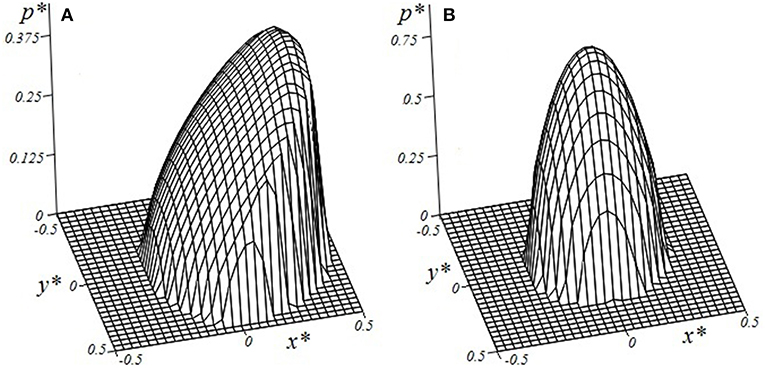
Figure 2. Contact pressure distribution within the contact area (V* = 1/3 (A), V* = 10 (B), h* = 0.1, c = 5, ν = 0.3, Q* = 0.15).
The dependence of friction coefficient μ* on sliding velocity is presented in Figure 3. The dependencies are non-monotonic. Together with an increase in sliding velocity, the energy dissipation first increases and then decreases. By comparing results for the layer and for the half-space, we conclude that generally maximum values of μ* are greater for the half-space, but at low sliding velocities the dissipation losses are higher for the layer.
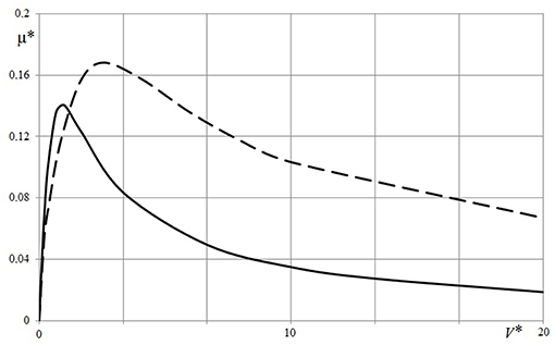
Figure 3. Dependence of friction coefficient on sliding velocity [h* = 0.1 (solid line), h* = ∞ (dashed line), c = 5, ν = 0.3, Q* = 0.05].
The effect of layer thickness on contact characteristics may be analyzed using results presented in Figures 4, 5. Contact pressure distribution within the central section of the indenter and plane Oy (Figure 4) were calculated using three values of layer thickness: (curves 1-3, respectively). The value of the sliding velocity was chosen so that the rheological properties of the material have a significant effect on the contact pressure distribution. It should be noted that the curve which corresponds to the case of the half-space, has specific bends. Similar results were previously obtained in Koumi et al. (2015), Goryacheva et al. (2015, 2016). For a relatively thin layer the shape of the curve is similar to the results obtained for the 1-D model of viscoelastic layer (Lyubicheva, 2008). The dependence of pressure maximum on layer thickness (Figure 5) was calculated for a relatively small value of the sliding velocity V* = 1/60 in which case the rheological properties of the material are poorly manifested. The dependence monotonically decreases.
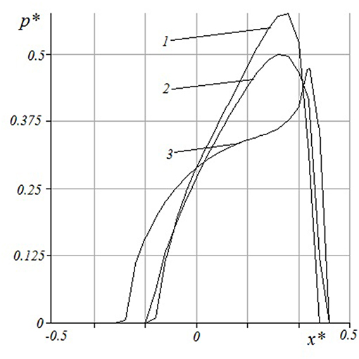
Figure 4. Contact pressure distribution within central section of indenter and plane Oy. h* = 0.03, 0.1, ∞(curves 1-3 respectively), c = 5, ν = 0.3, Q* = 0.1, V* = 0.05.
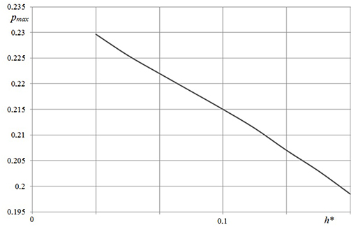
Figure 5. Dependence of maximum pressure value on layer thickness (c = 5, ν = 0.3, Q* = 0.1, V* = 1/60).
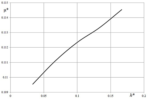
The influence of thickness of the viscoelastic layer on the friction coefficient was analyzed with the velocity, which provided a relatively large value friction coefficient (see Figure 6). The increase of thicker layers was predictable. It is interesting to note, that there was a 15% increase in the friction coefficient vs. the four time increase of thickness.
As the viscoelastic materials often are weakly compressible an important characteristic for analysis is the Poisson ratio (Figure 7).
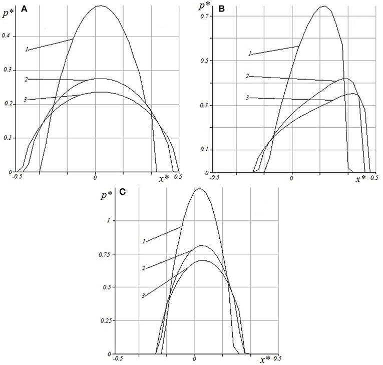
Figure 7. Contact pressure distribution for different velocities and Poisson ratio: V* = 1/60 (A), V* = 0.3 (B), V* = 10 (C), ν = 0.45;0.3;0.2 (curves 1-3 respectively), c = 5, h* = 0.1, Q* = 0.1.
The following values of the Poisson ratio were used in calculations: ν = 0.45;0.3;0.2 (lines 1–3, respectively). Also, three values of sliding velocities V* = 1/60 (Figure 7A), V* = 0.3 (Figure 7B), V* = 10 (Figure 7C) were considered. The presented results show that the Poisson ratio sufficiently influences the pressure distribution, both at small and at high velocities, when the pressure distribution is close to the elastic case (Figures 7A,C). This appears also in the case of a non-symmetric pressure distribution (Figure 7B). In the latter case it is interesting to analyze the effect of the Poisson ratio on the value. Curve 1 in Figure 7B corresponds to μ* = 0.1013; other values are μ* = 0.1357 (curve 2), and μ* = 0.1439 (curve 3).
The resulting contact pressure distributions were used for analysis of internal stresses in the viscoelastic layer. Figure 8 represents surface tensile-compressive stress distribution. Concentration of the tensile stresses may cause material damage. The maximum of the tensile-compressive stresses is located at the surface for all considered input parameters. Negative values of stresses are compressive, while positive values are tensile. The maximum of compressive stresses is located at the point of maximal contact pressure. The front of the contact area has stresses that are sharply differential from the positive to negative or zero values. Behind the contact zone local maxima of tension occurs. It was shown that tensile stresses mostly depend on the Poisson ratio and layer thickness. An essential decrease of tensile stresses in front of the contact area occurs due to an increase of the Poisson ratio and due to a decrease of the layer thickness.
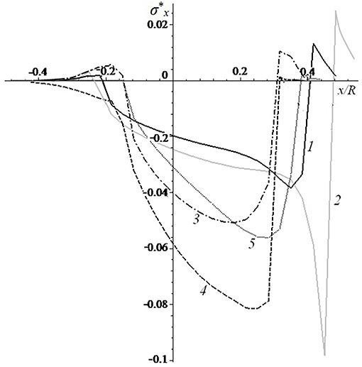
Figure 8. Surface tensile-compressive stc = 5ress distribution [V* = 0.333 (curves 1,2,4,5), V* = 1.666 (curve 3); c = 5 (curves 1, 3-5), c = 20 (curve 2); h* = 0.1 (curves 1-4), h* = 0.033 (curve 5); ν = 0.3 (curves 1-3, 5), ν = 0.45 (curve 4); Q′ = 0.1 (curves 1, 3-5), Q′ = 0.035 (curve 2)].
Figure 9 represents the calculation results for the distribution of stresses at the layer-substrate interface. The stresses are equal to zero at the layer surface and reach a maximum at the interface. Stress concentration may be a reason for layer delamination. Here only absolute values of stresses are considered because positive and negative signs define the direction of stress action. The stress maximum is located under the surface boundary. The absolute maximum of stresses appears under the front side of the contact area. The effect of the Poisson ratio is most significant for shear stresses: curves 1 and 4 are calculated for ν = 0.3 and 0.45, respectively, and the shear stress maxima are more than two times greater for a large Poisson ratio.
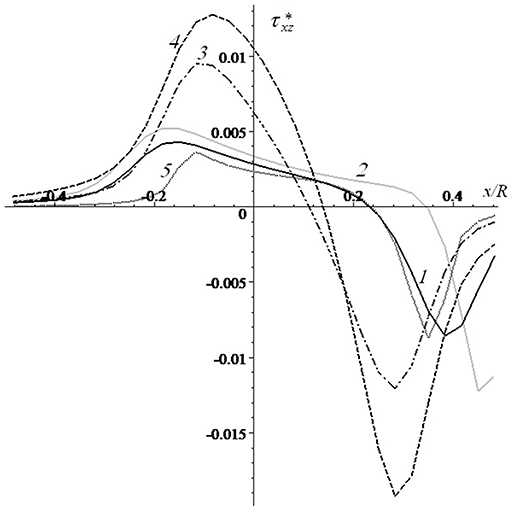
Figure 9. Distribution of stresses at the layer-substrate interface [V* = 0.333 (curves 1,2,4,5), V* = 1.666 (curve 3); c = 5 (curves 1, 3-5), c = 20 (curve 2); h* = 0.1 (curves 1-4), h* = 0.033 (curve 5); ν = 0.3 (curves 1-3,V* = 0.333 5), ν = 0.45 (curve 4); (curves 1, 3-5), Q′ = 0.035 (curve 2)].
Analysis of effect of layer thickness on principal shear stresses is presented in Figure 10 for different layer thicknesses. An almost symmetrical stress distribution was obtained for a relatively thick layer; which means that the layer thickness influences the detection of the rheological properties of the material in sliding contact. A layer thickness increase of five times, leads to a decrease of the maximum of the principal shear stress inside the layer by almost three times.
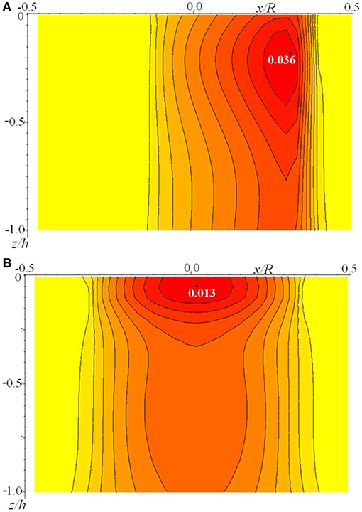
Figure 10. Dependence of principal shear stresses on layer thickness [V* = 0.333;c = 5;ν = 0.3;Q′ = 0.1;h* = 0.033 (A), h* = 0.166 (B)].
Viscoelastic Half-Space Coated by a Rigid Plate
Figure 11 represents the contact pressure distribution obtained for two different sliding velocities V* = 0.05 (Figure 11A); V* = 0.2 (Figure 11B). Both figures demonstrate the effect of rheology of the substrate which results in sufficient asymmetry of the contact area and pressure distribution. Here one can observe a “chair shape” effect in the pressure distribution in Figure 11A which occurs due to coating bend and substrate rheological properties. Figure 12 shows the contact pressure distribution at two different sliding velocities and four values of layer thickness. Here, the decrement of pressure in a center of a contact zone can be observed more explicitly. It is worth noting that this phenomenon occurs at relatively small values of layer thickness, while at thicker layers the pressure distribution tends to be more Hertz-like, which is foreseeable.
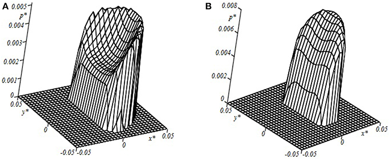
Figure 11. Contact pressure distribution within the contact area [c = 6; h* = 0.0133; ν = 0.4; Q′ = 2.0; V* = 0.05 (A); V* = 0.2 (B)].
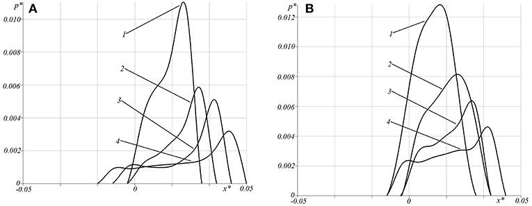
Figure 12. Contact pressure distribution for different velocities and layer thickness [c = 6; ν = 0.4; Q′ = 2.0; V* = 0.05 (A); V* = 0.2 (B), h* = 0.05 (curve 1), h* = 0.02 (curve 2), h* = 0.0133 (curve 3), h* = 0.0066 (curve 4)].
The effect of layer thickness on the friction coefficient was also analyzed. The results are presented in Figure 13 for two values of the sliding velocity. Curves 1 and 2 are almost of the same shape and arranged one above the other. Some non-monotonic dependence of sliding resistance on the coating thickness in the range of thin coatings can be observed. Herewith, generally the smaller value of sliding velocity shows the bigger amplitude of the friction coefficient.
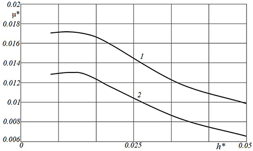
Figure 13. Dependence of friction coefficient on layer thickness. [c = 6; ν = 0.4; Q′ = 2.0; V* = 0.05(curve 1); V* = 0.2 (curve 2)].
Analysis of internal stresses due to contact interaction in an elastic substrate covered by essentially more hard coating (Goryacheva, 1998) leads to the conclusion, that stress at the coating-substrate interface is usually greater than in other points of the substrate. The results presented below (Figures 14, 15) illustrate the influence of the rigid plate thickness on the normal and tangential stresses at the interface for two different velocities. It can be noted, that for the thickest coating the normal stress distribution is the most uniform, but for the thin layer the distribution is closer to the contact pressure. It can explain the effect of a decrease in hysteretic losses with an increase in the coating thickness. The influence of the layer thickness on the interface tangential stresses is almost the same as for the viscoelastic layer bonded with a rigid substrate, which is described above.
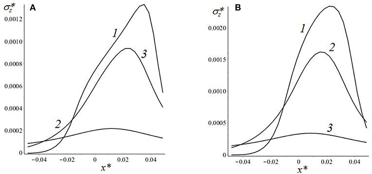
Figure 14. Normal stresses at the layer-substrate interface [c = 6; ν = 0.4; Q′ = 2.0; V* = 0.05; (A); V* = 0.2 (B); h* = 0.0066 (curve 1), h* = 0.0165 (curve 2), h* = 0.05 (curve 3)].
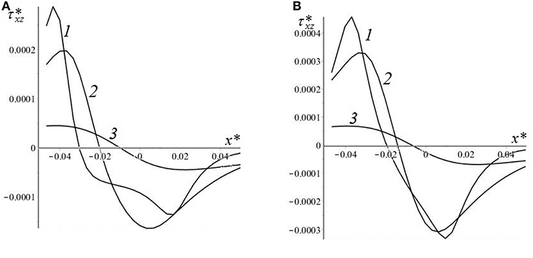
Figure 15. Tangential stresses at the layer-substrate interface [c = 6; ν = 0.4; Q′ = 2.0; V* = 0.05 (A); V* = 0.2 (B); h* = 0.0066 (curve 1), h* = 0.0165 (curve 2), h* = 0.05 (curve 3)].
Discussion
In this study, two cases were considered:
- a quasistatic sliding of a smooth indenter over a viscoelastic layer bonded with a rigid half-space as well as
- a quasistatic sliding of a smooth indenter over a rigid plate bonded with viscoelastic half-space.
A new numerical-analytical method of a solution based on the double integral Fourier transform was developed and used in both cases. Contact pressure distribution, friction coefficient, and stresses inside the viscoelastic layer or viscoelastic substrate were analyzed depending on input parameters.
In the case of viscoelastic half-space, the velocity, at which the maximum sliding resistance is observed, is dependent on the combination of the elastic, rheological properties of the material and on the normal load. For a viscoelastic coating (or coated viscoelastic substrate) the thickness of the layer must be added to this set. We found that for low velocities, the hysteretic losses in a layered system are higher than those in the case of the half-space with the same rheology. At higher sliding velocities, the dependency on the layer thickness is the opposite. Generally, the thicker the layer, the higher the maximum value of the friction coefficient is due to hysteretic losses. The opposite effect is obtained for the combination of a rigid coating and a viscoelastic substrate.
The effect of the Poisson ratio on the contact pressure is partially apparent: for elastic solids, higher values of contact pressure are found for low-compressive materials. More interesting is the finding that for low-compressible materials, large values of tangential stresses at the layer-substrate interface take place; which may cause a delamination process.
In the case of thin layers with a relatively low Poisson ratio, stresses are found to be weakly dependent on the coordinate z, therefore a 1-D model of the viscoelastic layer should provide a good approximation for the contact problem solution, with the exception of the stress distribution. An analysis of stresses inside the layer, or in the viscoelastic substrate, can be used to predict the coating fracture due to sliding.
Data Availability
All datasets generated for this study are included in the manuscript and/or the supplementary files.
Author Contributions
ET: problem formulation, analytical results. FS: calculations.
Funding
This research was funded by the Russian Science Foundation, grant 18-19-00574. The analysis of stresses in the viscoelastic layer (chapter Viscoelastic Layer and Rigid Substrate) falls under the framework of the grant from the Russian Foundation for Basic Research 19-08-00615.
Conflict of Interest Statement
The authors declare that the research was conducted in the absence of any commercial or financial relationships that could be construed as a potential conflict of interest.
References
Aleksandrov, V. M., and Goryacheva, I. G. (2005). “Moving with constant velocity of distributed load over a viscoelastic half-space,” in Proceedings of the 5th Russian Conference Mixed Problems of Deformable Bodies Mechanics (Saratov), 23-25.
Aleksandrov, V. M., Goryacheva, I. G., and Torskaya, E. V. (2010). Sliding contact of a smooth indenter and a viscoelastic half-space (3D problem), Doklady. Physics 55, 77–80. doi: 10.1134/S1028335810020084
Aleksandrov, V. M., and Mark, A. V. (2009). Quasistatic periodic contact problem for a viscoelastic layer, a cylinder, and a space with a cylindrical cavity. J. Appl. Mech. Tech. Ph. 50, 866–871. doi: 10.1007/s10808-009-0117-8
Bai, C., Liang, A., Cao, Z., Qiang, L., and Zhang, J. (2018). Achieving a high adhesion and excellent wear resistance diamond-like carbon film coated on NBR rubber by Ar plasma pretreatment. Diamond Relat. Mater. 89, 84–93 doi: 10.1016/j.diamond.2018.08.013
Goryacheva, I. G., Gubenko, M. M., and Makhovskaya, Y. Y. (2014). Sliding of a spherical indenter on a viscoelastic foundation with the forces of molecular attraction taken into account. J. Appl. Mech. Tech. Ph. 55, 81–88. doi: 10.1134/S0021894414010118
Goryacheva, I. G., Stepanov, F. I., and Torskaya, E. V. (2015). Sliding of a smooth indentor over a viscoelastic half-space when there is friction. J. Appl. Math. Mech. 79, 596–603. doi: 10.1016/j.jappmathmech.2016.04.006
Goryacheva, I. G., Stepanov, F. I., and Torskaya, E. V. (2016). Effect of Friction in Sliding Contact of a Sphere Over a Viscoelastic Half-Space, Mathematical Modeling and Optimization of Complex Structures (Berlin: Springer), 93–104.
Klüppel, M., and Heinrich, G. (2000). Rubber friction on self-affine road tracks. Rubber Chem. Technol. 73, 578–606. doi: 10.5254/1.3547607
Koumi, K. E., Chaise, T., and Nelias, D. (2015). Rolling contact of a rigid sphere/sliding of a spherical indenter upon a viscoelastic half-space containing an ellipsoidal inhomogeneity. J. Mech. Phys. Solids 80, 1–25. doi: 10.1016/j.jmps.2015.04.001
Lyubicheva, A. N. (2008). Analysis of mutual influence of contact spots in sliding of periodical system of asperities over Winkler viscoelastic foundation. J. Frict. Wear. 29, 125–133. doi: 10.3103/S1068366608020037
Mark, A. V. (2008). The uniform motion of rectangular and parabolic punches in a viscoelastic layer. J. Appl. Math. Mec. 72, 492–498. doi: 10.1016/j.jappmathmech.2008.08.002
Menga, N., Afferrante, L., and Carbone, G. (2016). Effect of thickness and boundary conditions on the behavior of viscoelastic layers in sliding contact with wavy profiles. J. Mech. Phys. Solids. 95, 517–529. doi: 10.1016/j.jmps.2016.06.009
Morozov, A. V., and Makhovskaya, Y. U. (2007). Theoretical-experimental assessment of deformational component of friction coefficient. J. Frict. Wear. 28, 335–344. doi: 10.3103/S1068366607040010
Nikishin, V. S., and Shapiro, G. S. (1970). Space Problems of Elasticity Theory for Multilayered Media, Vych. Moscow: Tsentr Akad Nauk SSSR.
Persson, B. N. J. (2001). Theory of rubber friction and contact mechanics. J. Chem. Phys. 115, 3840–3861. doi: 10.1063/1.1388626
Soldatenkov, I. A. (2015). Calculation of friction for indenter with fractal roughness that slides against a viscoelastic foundation. J. Frict. Wear. 36, 193–196. doi: 10.3103/S1068366615030137
Keywords: sliding contact, two-layered half-space, viscoelasticity, friction, hysteresis losses, internal stresses
Citation: Torskaya EV and Stepanov FI (2019) Effect of Surface Layers in Sliding Contact of Viscoelastic Solids (3-D Model of Material). Front. Mech. Eng. 5:26. doi: 10.3389/fmech.2019.00026
Received: 28 February 2019; Accepted: 17 April 2019;
Published: 09 May 2019.
Edited by:
Andrey I. Dmitriev, Institute of Strength Physics and Materials Science (ISPMS SB RAS), RussiaReviewed by:
Valentin L. Popov, Technische Universität Berlin, GermanyVladislav Aleshin, UMR8520 Institut d'électronique, de microélectronique et de nanotechnologie (IEMN), France
Copyright © 2019 Torskaya and Stepanov. This is an open-access article distributed under the terms of the Creative Commons Attribution License (CC BY). The use, distribution or reproduction in other forums is permitted, provided the original author(s) and the copyright owner(s) are credited and that the original publication in this journal is cited, in accordance with accepted academic practice. No use, distribution or reproduction is permitted which does not comply with these terms.
*Correspondence: Elena V. Torskaya, dG9yc2theWFAbWFpbC5ydQ==
 Elena V. Torskaya
 Fedor I. Stepanov