 Douglas Russell
 Andres San-Millan
 Vicente Feliu2
 Sumeet S. Aphale
- 1School of Engineering, University of Aberdeen, Aberdeen, UK
- 2Department of Electrical, Electronic and Automatic Control Engineering, University of Castilla-La Mancha, Ciadud Real, Spain
The Butterworth filter is known to have maximally flat response. Incidentally, the same response is desired in precise positioning systems. This paper presents a method for obtaining a closed-loop Butterworth filter pattern using common control schemes for positioning applications, i.e., Integral Resonant Control (IRC), Integral Force Feedback (IFF), Positive Position Feedback (PPF), and Positive Velocity and Position Feedback (PVPF). Simulations show a significant increase in bandwidth over traditional design methods and verify the desired pole placement is achieved. The simulations also show a significant limitation of the achievable bandwidth in the case of IRC, IFF, and PPF. For this reason, only PVPF is considered in experimental analysis. Experiments are performed using a two-axis serial kinematic nanopositioning stage. The results show a significant improvement in bandwidth, from 123 to 370 Hz, and increased positioning accuracy, specifically at the turn-around point, in comparison to the sequentially designed control scheme.
1. Introduction
Lightly damped resonant systems are highly susceptible to excitation of the resonant modes. This behavior can severely limit performance and lead to catastrophic failure of the system. Various control techniques have been proposed in the literature to improve the performance of these systems. Open-loop control schemes, such as filtering and model-based inversion techniques (Croft et al., 2001), have been used. The performance of open-loop systems is limited by the sensitivity to perturbations in the system dynamics and rely on a having a sufficiently accurate model. Closed-loop controllers are more commonly used due to superior robustness and excellent stability (Preumont, 1997). In this work, we consider a piezoactuated serial kinematic nanopositioning platform as an example system. Nanopositioners exhibit highly resonant behavior due to a lightly damped dominant resonant mode at relatively low frequency and non-linear behavior inherent to the piezoelectric actuators.
The effect of the low-frequency resonant mode on the performance of a nanopositioner is that the scanning speed at which accurate tracking can be achieved is limited to approximately one-hundredth of the resonant frequency in open-loop operation (Moheimani, 2008). In applications which require high scanning speeds (Ando et al., 2002; Tuma et al., 2012), a controller which damps the resonant mode is required. Numerous damping controllers have been presented in the literature. Integral Force Feedback (IFF) (Preumont et al., 2008) and Integral Resonant Control (IRC) (Aphale et al., 2007) are simple, easy to design control schemes which provide guaranteed stability and excellent robustness. Positive Position Feedback (PPF) (Fanson and Caughey, 1990) and Positive Velocity and Position Feedback (PVPF) (Bhikkaji et al., 2007) use the feedback of position, and position and velocity, respectively, to achieve closed-loop pole placements, which increase damping. This work will focus on IFF, IRC, PPF, and PVPF due to the simple design procedures. However, numerous other damping controllers exist and have been extensively reported, including Shunt control (Hagood and von Flotow, 1991), Resonant control (Aphale et al., 2008a), and H∞ control (Sebastian and Salapaka, 2005). These damping controllers are not limited in use to nanopositioning. Successful implementation has been reported in applications, such as robotic manipulators (Pereira et al., 2011), disk drives (Numasato and Tomizuka, 2003), aircraft wings (Friedmann and Millott, 1995), scanning probe microscopes (Fleming et al., 2010), MEMS/NEMS (Ferreira and Aphale, 2011), and high-density memory storage devices (Sebastian et al., 2008).
Non-linear behavior, such as hysteresis and creep, is observed in nanopositioning due to the use of piezoelectric actuators (Figure 1). The positioning error caused by non-linearities is significant and must be considered when designing an appropriate controller. A number of methods have been proposed in the literature to reduce the effects of non-linear behavior on the positioning error. The hysteretic behavior of piezoactuators can be linearized by driving with charge actuation (Newcomb and Flinn, 1982; Fleming, 2013), rather than the more commonly used voltage actuation. It has also been shown that the augmentation of linear controllers with non-linear damping reduces the effects of non-linearities on positioning error (Kanestrom and Egeland, 1994; Vagia et al., 2013). Fuzzy control has been applied to nanopositioning, incorporating non-linearities in the modeling of the plant, to design controllers, which directly target the non-linear behavior (Yu et al., 2009). The most common method of reducing the effects of non-linear behavior in nanopositioning is through the use of reference tracking (Devasia et al., 2007). Debate is ongoing with regard to whether linear controllers are suitable for the control of non-linearities. However, numerous works have shown, experimentally, that integral tracking control reduces the effects of hysteresis on positioning error (Bhikkaji et al., 2007; Aphale et al., 2008a; Fleming, 2010).
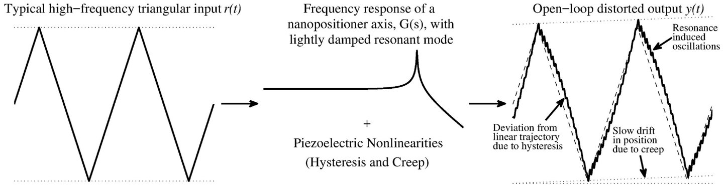
Figure 1. Interaction of input harmonics and plant dynamics. On the left is a typical input for nanopositioning systems, a high frequency triangular waveform. The typical frequency response of a lightly damped resonant system is presented in the center. On the right is the resultant distorted output showing the effects of the lightly damped resonance, creep, and hysteresis. Note: the effects have been exaggerated for illustrative purposes.
Eielsen et al. (2014) showed that using Model Reference Control to obtain a closed-loop Butterworth filter pattern provides increased performance over traditional damping and tracking controllers, in terms of bandwidth and positioning error. The aim of this work is to provide a quick and simple method of deriving controllers to obtain a closed-loop Butterworth filter pattern. This allows the user to improve performance with limited knowledge of control theory.
One reason for the relatively poor performance of traditional controller designs in precise positioning is that the damping and tracking controllers are designed sequentially. This is due to the fact that many of the common damping controllers used in nanopositioning were either originally employed as standalone damping controllers in other applications or based on such controllers. In this case, the original design process of the damping controller is followed. When the tracking controller is added and the gain tuned, the damped characteristics of the closed-loop system are altered.
The performance of the system can be improved by simultaneously design the damping and tracking controllers. By utilizing a simultaneous design process, the desired damping and tracking characteristics can be achieved in closed-loop operation.
The paper is structured as follows: Section 2 provides an overview of the IRC, IFF, PPF, and PVPF control schemes. Methods are provided for each control scheme to obtain the closed-loop Butterworth filter pattern. Section 3 details the experimental nanopositioning setup. In Section 4, controller parameters are derived for both traditional and Butterworth-based control schemes. Simulations are provided to evaluate the performance of the proposed controller in comparison with the traditional design. Section 5 presents experimental results for the PVPF case, showing the effectiveness of the Butterworth-based controller design in implementation. Section 6 concludes the paper.
2. Obtaining Butterworth Pattern
A number of methods have been proposed for the control of second-order systems. These range from PI control, commonly used in commercial Atomic Force Microscopes, to optimal control methods, such as H∞ (Sebastian and Salapaka, 2005). The ideal frequency response for tracking applications consists of unity gain at low frequencies to preserve the harmonics of the input, followed by a roll-off at high frequencies to reduce the effects of noise and high frequency unmodeled dynamics. The Butterworth filter is known to fit these criteria. The Butterworth filter is defined as having transfer function, H(s), such that the poles of H(s)H(−s) are equally spaced on a circle, with radius equal to the natural frequency of the Butterworth filter, in the Cartesian plane. In this section, a brief overview is given of the four control schemes used in this work and a method to achieve a closed-loop Butterworth filter pattern is presented.
First, we must consider the modeling of the plant. Nanopositioning platforms utilize collocated sensor/actuator pairs, which are modeled as the sum of multiple second-order transfer functions. However, the performance of a nanopositioner is limited by a dominant, low-frequency resonant mode. The nanopositioner can, therefore, be modeled as a single second-order system. This approach has been used extensively in the literature. The transfer function of the model, measured from the input voltage to the output displacement, is given by
where ζ is the damping ratio, ωn is the natural frequency, and σ is a constant gain determined by the physical characteristics of the plant. Although the controller design process, presented in the remainder of this section, utilizes a simplified model of the plant, the closed-loop performance is not degraded by the inclusion of higher-order modes.
2.1. Integral Resonant Control
Integral Resonant Control is an adaptation of IFF, whereby position feedback is used as opposed force feedback. In using position feedback, a feedthrough term is added to emulate the response of the force measurement. As this is no longer an inherent system parameter, the feedthrough can be arbitrarily chosen, giving greater control over the response. IRC has found wide use in a number of applications including nanopositioning (Aphale et al., 2008b; Bhikkaji and Moheimani, 2008), smart structures (Aphale et al., 2007), and flexible link manipulators (Pereira et al., 2011) due to the simplicity of the design method and the stability and robustness properties. The structure of the IRC scheme is shown in Figure 2A, where G(s) is the plant, d is an arbitrarily chosen constant gain, and Cd(s) is an integral controller given by
and the tracking controller, Ct(s), is an integral controller given by
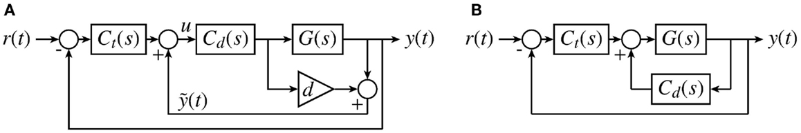
Figure 2. Block diagram of (A) the IRC/IFF and (B) the PPF/PVPF control schemes where G(s) is the plant, Cd (s) is the damping controller, Ct (s) is the tracking controller, and d is a constant gain, which can be chosen arbitrarily for IRC and is determined by the plant dynamics for IFF.
The traditional design procedure for IRC is as follows; first, the feedthrough, d, is chosen to be sufficiently large and negative. Then, the damping controller gain which provides maximum damping is found using the root-locus method. The tracking controller gain is found via trial-and-error. Further analysis has provided expressions for the feedthrough and damping controller gain, in terms of known parameters, which the maximum achievable damping (Namavar et al., 2014). Stability criteria are also provided which limits the range of tracking controller gains. However, it is known that the addition of the tracking controller affects the damped poles of the system, and it is observed that within the range of stability, the tracking controller gain and closed-loop damping ratio are inversely related. It is, therefore, necessary to design both the damping and tracking controllers simultaneously. In the remainder of this section, expressions are derived for the three tunable parameters, which will give a closed-loop Butterworth filter pattern.
From Figure 2A and the structure of the controllers as given previously, the closed-loop transfer function is derived as
where denotes the numerator and the denominator of the closed-loop transfer function.
A fourth-order Butterworth filter has two sets of complex poles with the same natural frequency and differing damping ratios. The denominator of the transfer function is given by
where
Equating the coefficients of the denominator of the closed-loop transfer function, in equation (4), and the characteristic equation of the Butterworth filter, in equation (6), gives the conditions for achieving a closed-loop Butterworth filter pattern, i.e.,
Rearranging equations (8)–(11) to find the controller parameters gives
Equating equations (12) and (13) and rearranging for ωd gives
The roots of equation (16) give the achievable damped natural frequency and are calculated as
With the damped natural frequency, ωd, now known, the damping controller gain, k, can be found by equating equations (12) and (14) giving
The feedthrough term, d, is then calculated from equation (12) as
and the tracking controller gain, kt, given by equation (15).
2.2. Integral Force Feedback
Integral Force Feedback was first proposed by Preumont et al. to damp the vibrations in space structures (Preumont et al., 1992). This method has since been refined (Preumont et al., 2008) and applied to other resonant systems, such as nanopositioning stages (Fleming, 2010). IFF with tracking control has the same structure as IRC, see Figure 2A, where Cd and Ct are both integral controllers. There are two main differences between IFF and IRC: first, IFF uses force feedback in the damping loop, whereas IRC uses position feedback. Second, the feedthrough term, d, is fixed and determined by properties of the system in IFF, IRC allows an arbitrary choice of feedthrough. In recent work, Optimal Integral Force Feedback (OIFF) has been developed (Teo et al., 2014). This entails the addition of an arbitrarily chosen feedthrough term, β, such that the feedback in the damping loop, , is given by
where dt is the total feedthrough gain, defined as dt = d + β. The benefit of this method is an increase in the achievable damping and improved robustness. To achieve a closed-loop Butterworth pattern, the OIFF control scheme can be designed using the same method as IRC. The feedthrough, dt, is calculated using equation (19). The additional feedthrough is then β = dt − d. The integral damping and tracking controllers are unchanged.
2.3. Positive Position Feedback
Positive Position Feedback was originally developed for the control of large space structures (Goh and Caughey, 1985; Fanson and Caughey, 1990). It has since been successfully applied to nanopositioning stages (Aphale et al., 2008a). Traditionally, PPF uses a pole placement algorithm to design the damping controller, . The closed-loop pole placement can be chosen arbitrarily. The controller is derived by equating the coefficients of the desired characteristic equation with those of the denominator of the closed-loop transfer function and solving for the controller parameters. However, due to the limitations of the PPF controller, the desired pole placement cannot always be achieved. The tracking controller gain is found via trial-and-error.
To obtain a closed-loop Butterworth filter pattern, the same method as for IRC is used, i.e., the denominator of the closed-loop transfer function is equated to the characteristic equation of the Butterworth filter. However, due to additional complexity of the higher-order system, some parameters must be found numerically.
The structure of the PPF control scheme with tracking is shown in Figure 2B where the PPF controller, Cd has transfer function
and the tracking controller, Ct, is an integrator given by
The closed-loop transfer function is given by
The fifth-order Butterworth filter has the following characteristic equation
where
Substituting the values for ϕ1, ϕ2, and ωd gives the characteristic equation in the form
Equating the denominator coefficients of equation (23) with equation (27) and rearranging for the controller parameters gives
As PPF does not allow arbitrary pole placement, a closed-loop Butterworth filter pattern can only be achieved for a specific damped natural frequency, ωd. This is found numerically such that
where si are the roots of denominator of equation (23).
2.4. Positive Velocity and Position Feedback
Positive Velocity and Position Feedback (PVPF) is an adaptation of PPF. The addition of velocity feedback allows truly arbitrary pole placement to be achieved, where there is a limitation of the achievable pole placement of PPF. Successful implementation of the PVPF control scheme in nanopositioning applications has been widely reported in the literature (Bhikkaji et al., 2007; Aphale et al., 2008a; Bazaei et al., 2012). The design procedure of the PVPF controller is similar to that of the PPF controller. The desired closed-loop pole placement is chosen, typically by reducing the real component of the plant poles by a sufficiently large amount, such that the damping ratio is increased while maintaining the damped natural frequency of the plant. The tracking controller is designed via trial-and-error.
As PVPF allows arbitrary pole placement, the closed-loop Butterworth filter pattern can be easily achieved using a method similar to the traditional design. The only difference is that the tracking controller must be taken into account in the design process.
The structure of the PVPF control scheme with tracking is shown in Figure 2B, where the damping controller, Cd has transfer function
and the tracking controller is an integrator given by
The closed-loop transfer function is
The fifth-order Butterworth filter has the following characteristic equation
where α and β are given by equations (25) and (26), respectively.
As PVPF allows arbitrary pole placement, the values for ϕ1, ϕ2, and ωd can be substituted giving a characteristic equation of the form
Equating this with equation (32) gives the controller parameters as
In the following sections, the proposed methods for designing the IRC, PPF, and PVPF control schemes are applied to a nanopositioning stage. IFF will not be considered due to the similarity with IRC. The performance of the Butterworth-based controllers is evaluated against the controllers derived using the traditional design methods.
2.5. Note on Parameter Selection
The design methods presented in this section are generalized and contain some undefined parameters. This following will clarify the available choices.
In the case of IRC and IFF, in order to obtain a closed-loop Butterworth filter pattern, the desired closed-loop damping ratios must be defined as γ1 = 0.9239 and γ2 = 0.3827. This is necessary to ensure a fourth-order closed-loop Butterworth filter pattern. This consequently defines α and β and allows controller parameters to be derived for a given plant.
For PPF and PVPF, the desired closed-loop damping ratios must be defined as: ϕ1 = 0.8090 and ϕ2 = 0.3090, in order to ensure a fifth-order Butterworth filter pattern is achieved. In the case of PPF, the natural frequency at which the Butterworth filter pattern can be achieved has, thus far, only been found by numerical analysis for a given plant. For PVPF, a closed-loop Butterworth filter pattern can, theoretically, be achieved for any choice of cutoff frequency, ωd. In practice, it is noted that large choices of ωd can cause instability. It is recommended that the chosen natural frequency of the Butterworth filter does not exceed the natural frequency of the plant.
3. Experimental Setup
The performance of the Butterworth-based controller is evaluated on a two-axis serial kinematic nanopositioner, pictured in Figure 3. The nanopositioner was designed and constructed at the EasyLab, University of Nevada, Reno. The stage is driven by two 10-mm 200-V piezoelectric stack actuators that provide a range of 40 μm in each axis. The position is measured by a Microsense 6810 capacitive sensor and 6504-01 probe with a sensitivity of 5 μm/V. The stage is driven by two PiezoDrive PDL200 voltage amplifiers with a gain of 20. The control algorithm is implemented using NI LabVIEW’s Real-Time module at a sampling rate of 20 kHz.
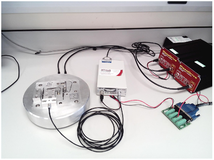
Figure 3. A two-axis serial kinematic nanopositioner, designed at the EasyLab, University of Nevada, Reno, driven by two PiezoDrive 200V Linear amplifiers, with position measured by a Microsense 4810 capacitive sensor.
4. Simulations
Simulations are performed using a second-order model derived from the measured frequency response, see Figure 4, of one-axis of the nanopositioner described in the previous section. The model is calculated to model the dominant resonant mode of the nanopositioner and is given by
that is, in terms of the plant parameters of equation (1), σ = 3148.2, ζ = 0.0102, and ωn = 4501.1.
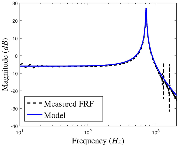
Figure 4. The measured magnitude response of the nanopositioning platform and the second-order model.
The remainder of this section presents the design process of both the traditional and Butterworth-based control schemes for IRC, PPF, and PVPF. IFF has not been included due to the similarity to IRC. The simulations focus on frequency-domain results to ensure stability, and that the closed-loop Butterworth pattern is achieved. Bandwidth measurements are provided for comparison of the traditional and Butterworth-based controllers’ performance.
4.1. IRC
4.1.1. Traditional Design
The traditional IRC scheme is designed using the method developed by (Namavar et al., 2014) to achieve maximum damping. The feedthrough term, d, and damping controller gain, are derived as functions of plant parameters. The tracking controller gain is found via trial-and-error such that the closed-loop magnitude response does not exceed unity gain.
4.1.2. Butterworth-Based Design
To achieve a fourth-order Butterworth pattern, the required closed-loop damping ratios are given as
From equation (17), the maximum achievable damped natural frequency is found to be ωd = 2471.2 rad/s. Equations (15), (18), and (19) give the following controllers
4.2. PPF
4.2.1. Traditional Design
The traditional PPF scheme is designed using the method found in (Aphale et al., 2008a). In this case, the design criteria are to maintain the damped natural frequency and increase the damping ratio to 0.37. This damping ratio is chosen as a rough approximation of the achieved damping ratios found in the literature. Damping ratio is used as opposed to coordinates as it is irrespective of system resonances. The tracking controller gain is found via trial-and-error, such that the magnitude response does not exceed 0 dB at any point. This gives the following controllers
4.2.2. Butterworth-Based Design
The closed-loop damping ratios are
The damped natural frequency, ωd, is found via simulation. Over a range of ωd, the desired characteristic equation is calculated and damping and tracking controllers designed using equation (28). The closed-loop transfer function is derived and the poles are found. We choose ωd as the frequency at which
This gives ωd = 3655.3. Equation (28) gives the PPF and tracking controllers as
4.3. PVPF
4.3.1. Traditional Design
The traditional PVPF controller is designed in the same way as the PPF controller, the only difference being the additional parameter in the numerator relating to velocity. The damping controller is designed to give a closed-loop damping ratio of 0.37, and the tracking controller gain found via trial-and-error to ensure the magnitude response does not exceed 0 dB. The damping and tracking controllers are calculated as follows
4.3.2. Butterworth-Based Design
The closed-loop damping ratios are
and the damped natural frequency is set to ωd = ωn. This gives the following characteristic equation
The controllers are derived from equation (36) as
The simulated closed-loop frequency response of both the traditional and Butterworth-based control schemes of IRC, PPF, and PVPF are presented in Figure 5 and the measured bandwidth given in Table 1. The bandwidth is defined as the lowest frequency at which the magnitude response of the system breaches the specified limits. Both positive and negative limits are imposed as an increase in magnitude can cause performance degradation equal to that of a reduction in magnitude. For nanopositioning applications, which require highly accurate tracking, the standard −3 dB bandwidth is not sufficiently stringent (Namavar et al., 2014). For this reason, the ±1 dB bandwidth is considered as a more pertinent performance metric. The ±3 dB bandwidth is also included for comparison. Figure 6 shows the closed-loop pole-zero map of the Butterworth-based designs.
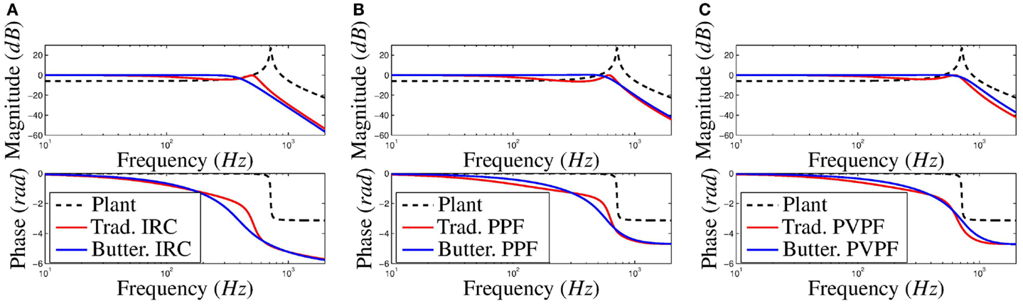
Figure 5. Simulated open- and closed-loop (damped and tracked) frequency response of both the traditional and Butterworth-based designs for (A) IRC, (B) PPF, and (C) PVPF.
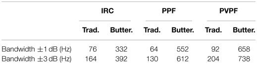
Table 1. Simulation results.
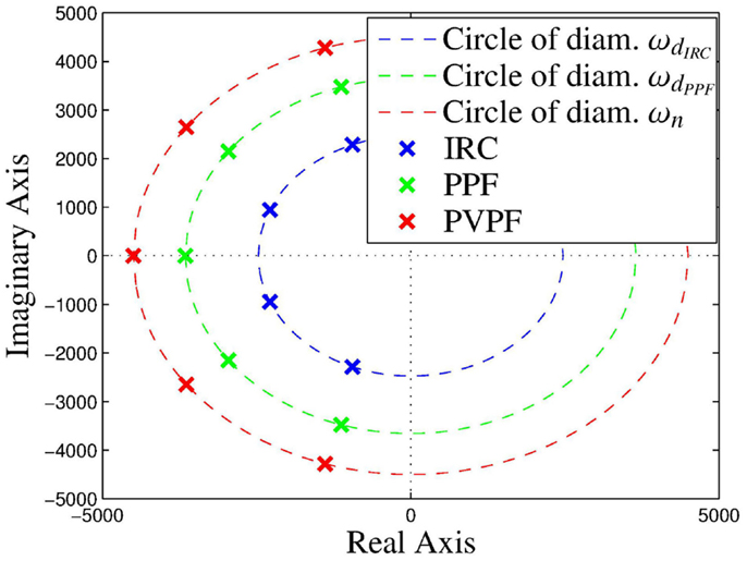
Figure 6. Pole-zero map of the Butterworth-based IRC, PPF, and PVPF damped and tracked closed-loop system, showing the achieved Butterworth filter pattern.
5. Experimental Results
Experiments were performed using the nanopositioning platform as described in Section 3. The performance of the control scheme was evaluated in both the frequency- and time-domain. In Section 2, it was found that in the case of IRC and PPF, the closed-loop Butterworth filter pattern can only be achieved for a single cutoff frequency, ωd. The application in Section 4 shows that the cutoff frequency attained using IRC and PPF is significantly less than that of the PVPF scheme. Additionally, using PVPF a closed-loop Butterworth filter pattern can be achieved for a large range of natural frequencies. For this reason, the PVPF based control scheme is deemed to be of greater use, and, as such, is the sole consideration of experimental analysis.
5.1. Frequency-Domain Results
The closed-loop frequency response function of both the traditional and Butterworth-based PVPF control schemes is plotted in Figure 7. The implementation is seen to be stable. It is observed that the results largely match the simulated results. The Butterworth-based PVPF control scheme does not display the frequency response of a perfect Butterworth filter. There is a minor increase in magnitude from approximately 100 to 250 Hz, followed by a premature decrease from approximately 300 to 700 Hz. Thorough testing of the experimental platform indicates that this can be attributed to the delay found in the controller implementation. This accounts for the relatively low ±1 dB bandwidth although the ±3 dB bandwidth is sufficiently similar to that predicted by simulation. In comparison with the traditionally designed PVPF control scheme, it is observed that the achievable bandwidth is significantly increased.
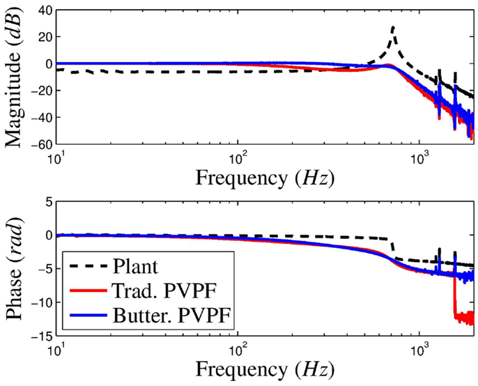
Figure 7. Experimentally measured closed-loop frequency response of the nanopositioning platform for the traditional and Butterworth-based PVPF control schemes.
5.2. Time-Domain Results
To measure the time-domain performance of the respective control schemes, the platform is subjected to a triangular input waveform, as is typical in nanopositioning applications. The triangular wave has a frequency of 35 Hz and an amplitude of 20 μm. The phase-corrected system response and error are shown in Figure 8 and the respective maximum and RMS error measurements are provided in Table 2.
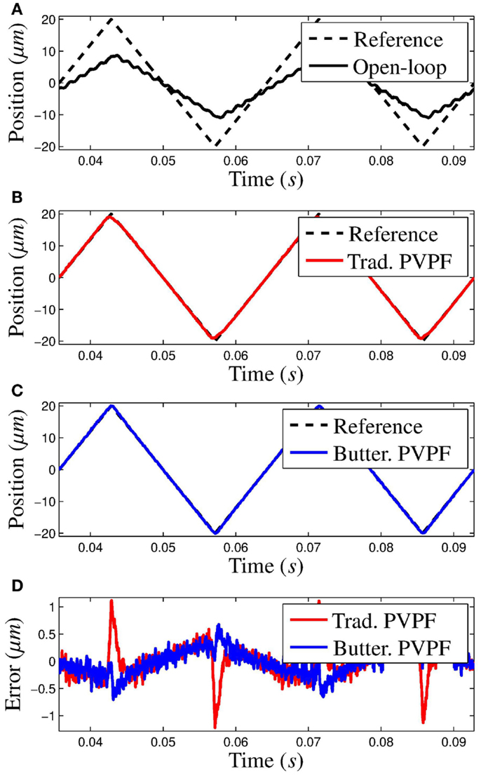
Figure 8. Response of the system to a 35-Hz triangular waveform with amplitude 20 μm for the following cases: (A) open-loop, (B) traditional PVPF design, and (C) Butterworth-based PVPF design. (D) shows the measured error signal for the traditional and Butterworth-based PVPF designs.
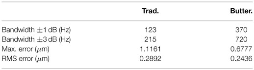
Table 2. Experimental results.
The open-loop response, plotted in Figure 8A, shows the triangular wave excites the resonance of the plant. The gain of the plant is significantly less than unity, and so, provides no tracking. Comparing the response of the traditional PVPF, Figure 8B, and the Butterworth-based PVPF, Figure 8C, it is observed that the Butterworth-based control scheme tracks more accurately, especially at the turn-around point. This is reflected in the error signal (Figure 8D) and the maximum recorded error (see Table 2). The traditional PVPF scheme shows a significant deviation from the reference, whereas the error of the Butterworth-based scheme at the turn-around is nearly indistinguishable from the rest of the scan. This effect becomes more pronounced at higher scan frequencies, due to the dip in the magnitude response of the traditional PVPF scheme. This causes a reduction of the gain in the lower harmonics of the triangle waveform. The relatively flat response of the Butterworth-based control scheme ensures the harmonics of the triangle wave will be preserved as the scanning speed is increased.
6. Conclusion
In this paper, a method is derived to obtain a Butterworth filter pattern in the damped and tracked response of a second-order system for each of the following four control schemes: Integral Resonant Control, Integral Force Feedback, Positive Position Feedback, and Positive Velocity and Position Feedback. Simulations show that the desired pole placement is achieved and this is reflected in frequency response. Using this method, a higher bandwidth can be achieved, which allows a greater accuracy in positioning. This is confirmed by experimental results. Due to the simplicity of the method, this is ideal for improving the performance of precise positioning systems.
Author Contributions
DR developed the theory of Butterworth-based simultaneous design of damping and tracking controllers presented in the paper and drafted the submitted manuscript. AS-MR conducted all of the experimental work and helped with the development of the theory and writing. SA supervised DR for theoretical development as well as AS-MR for the experimental setup and validation. VF provided guidance regarding theoretical development and gave inputs into paper writing.
Conflict of Interest Statement
The authors declare that the research was conducted in the absence of any commercial or financial relationships that could be construed as a potential conflict of interest.
References
Ando, T., Kodera, N., Maruyama, D., Takai, E., Saito, K., and Toda, A. (2002). A high-speed atomic force microscope for studying biological macromolecules in action. Jpn. J. Appl. Phys. 41, 4851–4856. doi:10.1143/JJAP.41.4851
Aphale, S. S., Bhikkaji, B., and Moheimani, S. R. (2008a). Minimizing scanning errors in piezoelectric stack-actuated nanopositioning platforms. IEEE Trans. Nanotechnol. 7, 79–90. doi:10.1109/TNANO.2007.910333
Aphale, S. S., Fleming, A. J., and Moheimani, S. O. R. (2008b). “A second-order controller for resonance damping and tracking control of nanopositioning systems,” in 19th International Conference on Adaptive Structures and Technologies, Ascona, Switzerland.
Aphale, S. S., Fleming, A. J., and Moheimani, S. O. R. (2007). Integral resonant control of collocated smart structures. Smart Mater. Struct. 16, 439–446. doi:10.1088/0964-1726/16/2/023
Bazaei, A., Yong, Y. K., Moheimani, S. O. R., and Sebastian, A. (2012). Tracking of triangular references using signal transformation for control of a novel AFM scanner stage. IEEE Trans. Control Syst. Technol. 20, 453–464. doi:10.1109/TCST.2011.2114347
Bhikkaji, B., and Moheimani, S. O. R. (2008). Integral resonant control of a piezoelectric tube actuator for fast nanoscale positioning. IEEE/ASME Trans. Mechatron. 13, 530–537. doi:10.1109/TMECH.2008.2001186
Bhikkaji, B., Ratnam, M., Fleming, A. J., and Moheimani, S. O. R. (2007). High-performance control of piezoelectric tube scanners. IEEE Trans. Control Syst. Technol. 15, 853–866. doi:10.1109/TCST.2007.902947
Croft, D., Shed, G., and Devasia, S. (2001). Creep, hysteresis, and vibration compensation for piezoactuators: atomic force microscopy application. J. Dyn. Syst. Meas. Control 123, 35–43. doi:10.1115/1.1341197
Devasia, S., Eleftheriou, E., and Moheimani, S. O. R. (2007). A survey of control issues in nanopositioning. IEEE Trans. Control Syst. Technol. 15, 689–703. doi:10.1109/TCST.2007.903345
Eielsen, A. A., Vagia, M., Gravdahl, J. T., and Pettersen, K. Y. (2014). Damping and tracking control schemes for nanopositioning. IEEE/ASME Trans. Mechatron. 19, 432–444. doi:10.1109/TMECH.2013.2242482
Fanson, J. L., and Caughey, T. K. (1990). Positive position feedback control for large space structures. AIAA J. 28, 717–724. doi:10.2514/3.10451
Ferreira, A., and Aphale, S. S. (2011). A survey of modeling and control techniques for micro- and nanoelectromechanical systems. IEEE Trans. Syst. Man Cybern. C Appl. Rev. 41, 350–364. doi:10.1109/TSMCC.2010.2072779
Fleming, A. J. (2010). Nanopositioning system with force feedback for high-performance tracking and vibration control. IEEE/ASME Trans. Mechatron. 15, 433–447. doi:10.1109/TMECH.2009.2028422
Fleming, A. J. (2013). Charge drive with active dc stabilization for linearization of piezoelectric hysteresis. IEEE Trans. Ultrason. Ferroelectr. Freq. Control 60, 1630–1637. doi:10.1109/TUFFC.2013.2745
Fleming, A. J., Aphale, S. S., and Moheimani, S. O. R. (2010). A new method for robust damping and tracking control of scanning probe microscope positioning stages. IEEE Trans. Nanotechnol. 9, 438–448. doi:10.1109/TNANO.2009.2032418
Friedmann, P. P., and Millott, T. A. (1995). Vibration reduction in rotorcraft using active control: a comparison of various approaches. J. Guid. Control Dyn. 18, 664–673. doi:10.2514/3.21445
Goh, C. J., and Caughey, T. K. (1985). On the stability problem caused by finite actuator dynamics in the collocated control of large space structures. Int. J. Control 41, 787–802. doi:10.1080/0020718508961163
Hagood, N., and von Flotow, A. (1991). Damping of structural vibrations with piezoelectric materials and passive electrical networks. J. Sound Vib. 146, 243–268. doi:10.1016/0022-460X(91)90762-9
Kanestrom, R. K., and Egeland, O. (1994). Nonlinear active vibration damping. IEEE Trans. Automat. Contr. 39, 1925–1928. doi:10.1109/9.317126
Moheimani, S. O. R. (2008). Invited review article: accurate and fast nanopositioning with piezoelectric tube scanners: emerging trends and future challenges. Rev. Sci. Instrum. 7, 071101. doi:10.1063/1.2957649
Namavar, M., Fleming, A. J., Aleyaasin, M., Nakkeeran, K., and Aphale, S. S. (2014). An analytical approach to integral resonant control of second-order systems. IEEE Trans. Mechatron. 19, 651–659. doi:10.1109/TMECH.2013.2253115
Newcomb, C., and Flinn, I. (1982). Improving the linearity of piezoelectric ceramic actuators. Electron. Lett. 18, 442–444. doi:10.1049/el:19820301
Numasato, H., and Tomizuka, M. (2003). Settling control and performance of a dual-actuator system for hard disk drives. IEEE/ASME Trans. Mechatron. 8, 431–438. doi:10.1109/TMECH.2003.819999
Pereira, E., Aphale, S. S., Feliu, V., and Moheimani, S. O. R. (2011). Integral resonant control for vibration damping and precise tip-positioning of a single-link flexible manipulator. IEEE/ASME Trans. Mechatron. 16, 232–240. doi:10.1109/TMECH.2009.2039713
Preumont, A., de Marneffe, B., Deraemaeker, A., and Bossens, F. (2008). The damping of a truss structure with a piezoelectric transducer. Comput. Struct. 86, 227–239. doi:10.1016/j.compstruc.2007.01.038
Preumont, A., Dufour, J.-P., and Malekian, C. (1992). Active damping by a local force feedback with piezoelectric actuators. AIAA J. Guid. Control Dyn. 15, 390–395. doi:10.2514/3.20848
Sebastian, A., Pantazi, A., Moheimani, S. O. R., Pozidis, H., and Eleftheriou, E. (2008). Achieving sub-nanometer precision in a mems storage device during self-servo write process. IEEE Trans. Nanotechnol. 7, 586–595. doi:10.1109/TNANO.2008.926441
Sebastian, A., and Salapaka, S. M. (2005). Design methodologies for robust nano-positioning. IEEE Trans. Control Syst. Tech. 13, 868–876. doi:10.1109/TCST.2005.854336
Teo, Y. R., Russell, D., Aphale, S. S., and Fleming, A. J. (2014). Optimal integral force feedback and structured pi tracking control: application for objective lens positioner. Mechatronics 24, 701–711. doi:10.1016/j.mechatronics.2014.04.004
Tuma, T., Lygeros, J., Kartik, V., Sebastian, A., and Pantazi, A. (2012). High-speed multiresolution scanning probe microscopy based on lissajous scan trajectories. Nanotechnology 23, 185501. doi:10.1088/0957-4484/23/18/185501
Vagia, M., Eilsen, A. A., Gravdahl, J. T., and Pettersen, K. Y. (2013). “Design of a nonlinear damping control scheme for nanopositioning,” in IEEE/ASME International Conference on Advanced Intelligent Mechatronics, Wollongong.
Keywords: nanopositioning, damping control, tracking control, integral resonant control, positive position feedback, positive velocity and position feedback
Citation: Russell D, San-Millan A, Feliu V and Aphale SS (2016) Butterworth Pattern-based Simultaneous Damping and Tracking Controller Designs for Nanopositioning Systems. Front. Mech. Eng. 2:2. doi: 10.3389/fmech.2016.00002
Received: 03 November 2015; Accepted: 12 February 2016;
Published: 01 March 2016
Edited by:
Yuen Kuan Yong, The University of Newcastle, AustraliaCopyright: © 2016 Russell, San-Millan, Feliu and Aphale. This is an open-access article distributed under the terms of the Creative Commons Attribution License (CC BY). The use, distribution or reproduction in other forums is permitted, provided the original author(s) or licensor are credited and that the original publication in this journal is cited, in accordance with accepted academic practice. No use, distribution or reproduction is permitted which does not comply with these terms.
*Correspondence: Sumeet S. Aphale, cy5hcGhhbGVAYWJkbi5hYy51aw==