
94% of researchers rate our articles as excellent or good
Learn more about the work of our research integrity team to safeguard the quality of each article we publish.
Find out more
ORIGINAL RESEARCH article
Front. Mater., 24 March 2025
Sec. Energy Materials
Volume 12 - 2025 | https://doi.org/10.3389/fmats.2025.1563997
 L. Ehl
1,2*
L. Ehl
1,2*
 N. Scherer
1
N. Scherer
1
 D. Zimmermann
1,2
D. Zimmermann
1,2
 I. Trofimenko
1
I. Trofimenko
1
 P. Molitor
1
P. Molitor
1
 S.-M. Kirsch
1
S.-M. Kirsch
1
 F. Louia
2
F. Louia
2
 P. Motzki
1,2*
P. Motzki
1,2*The elastocaloric effect offers a promising alternative to conventional compressor-based heating and cooling systems. This technology leverages solid-state phase transformations with high energy densities, eliminating the need for environmentally harmful refrigerants. As a result, elastocaloric systems can be developed for both heating and cooling applications that are sustainable, highly efficient, and scalable. In this study, the first elastocaloric “mini-fridge” operating under tensile load is developed, using air as heat transfer medium. This system is based on the world’s first continuously operating air-to-air elastocaloric machine demonstrator. The primary focus of this study is to investigate the transition from a generic technology demonstrator to an application-oriented system. A simulation tool enables investigation and optimization of various machine parameters such as material dimensions, load profiles, and latent heats for the intended application. The application targeted in this study is a “mini-fridge” designed to cool a standard 0.25 L beverage can. Shape memory alloy wire bundles are subjected to loading and unloading cycles by a patented energy converter. To effectively harness the latent heat released during phase transformation, the air must be optimally directed over the wire bundles. The cooling process is achieved by continuously circulating air around the bundles, progressively cooling a volume. The simulation tool is employed to determine the optimal geometric and process parameters for this system. The study aims to develop the first continuously operating elastocaloric “mini-fridge” with an internal cooling volume. To validate the entire setup, the inner chamber is equipped with temperature sensors to monitor the cooling performance. These sensors are strategically placed along the axis of rotation to measure the temperature as air enters and exits the chamber. The initial measurements achieved a temperature difference of approximately 3.5 K within the cooling chamber versus a simulated value 8.7 K, which did not include all possible losses present in the system. The simulation suggests a system COP at steady state of 5.8, which must be experimentally verified in future work.
Elastocaloric materials, which exhibit significant temperature changes (up to 23 K, depending on the material (Qian et al., 2016a)), represent a transformative approach to cooling technologies. These materials undergo a solid-state phase transformation driven by mechanical stress, eliminating the need for volatile refrigerants to cool gases or fluids. This first-order transformation yields high latent heats (up to 30 J/g) (Frenzel et al., 2015) and material COPs (Wieczorek et al., 2017), making elastocaloric technology a sustainable and efficient alternative to traditional methods. The most extensively researched and promising elastocaloric materials today are alloys based on nickel and titanium (NiTi). These materials are widely available on Earth, with significant reserves distributed across North America, Australia, Scandinavia, and Malaysia. (BGR, 2025; BGR, 2014). Besides elastocalorics (application of mechanical stress), other caloric effects have been observed in certain materials (Fähler et al., 2012; Mañosa et al., 2013; Moya et al., 2014). These include the magnetocaloric effect (application of a magnetic field) (Tishin and Spichkin, 2016; Smith et al., 2012; Kitanovski et al., 2015; Zimm et al., 1998), electrocaloric effect (application of an electric field) (Defay et al., 2013; Le Goupil et al., 2014) and the barocaloric effect (application of hydrostatic pressure) (Mañosa et al., 2010; cf. Tušek et al., 2015).
But unlike these competing technologies elastocaloric materials do not rely on critical or costly rare-earth elements. In response to a rising demand for eco-friendly technologies, elastocaloric materials have garnered significant attention, with both the U.S. Department of Energy and the European Commission identifying them as the most promising alternatives to vapor-compression systems (Goetzler et al., 2014). Conventional cooling methods, such as vapor-compression refrigeration, rely on chemical refrigerants with high global warming potential (GWP). These systems not only consume significant energy but also contribute to environmental degradation, as highlighted in the Intergovernmental Panel on Climate Change (IPCC) report. According to the report, carbon dioxide contributes 0.7 K to global warming, while greenhouse gases, including coolants, account for a collective warming of 1.5 K IPCC (2021). The refrigerants used in current cooling systems exacerbate this issue, both through direct emissions and through leakage during the cooling process. The rising global temperatures and rapid urbanization have led to a surge in demand for cooling technologies, with the International Energy Agency (IEA) projecting that over 5.6 billion air conditioning systems will be in use by 2050 (Peters, 2018). Elastocaloric materials offer a compelling solution by providing an efficient cooling effect without harmful refrigerants, thereby mitigating energy consumption and environmental impact. This paper explores the fundamental principles, potential applications, and challenges associated with elastocaloric materials in various domains, particularly focusing on their integration into thermal management and refrigeration technologies. Subsequently, the development process of an elastocaloric “can cooler” will be presented, demonstrating the practical application and potential of this innovative technology.
The development of the first technological demonstrator as a cooling system has been carried out by the research group Takeuchi et al. in 2012 (Saylor, 2012). Since then, various system concepts and architectures for elastocaloric cooling and heating have been developed and implemented in demonstration devices (Kirsch et al., 2018a). In 2016 Qian et al. has presented the first compression-based system using water as heat transfer medium (Qian et al., 2016b), also Tusek et al. has shared the work over the first regenerative tensile-loaded elastocaloric system (Tušek et al., 2016). The approach with thin metal foils was introduced by Ossmer et al. (2016a). Two systems were exhibited in 2018. On the one hand by Bruederlin et al. the approach with thin metal foils (Bruederlin et al., 2018), and on the other hand the first demonstrator for continuously cooling by Kirsch et al. (2018b). Three years later in 2021 the Fraunhofer (Bartholomé) has introduced their “Active Elastocaloric Heatpipe” (AEH) (Bachmann et al., 2021; Ianniciello et al., 2022). In 2023 the University of Naples presented two concepts, the first Italian rotary demonstrator device for air conditioning (Borzacchiello et al., 2023; Cirillo et al., 2024), and the loading-through-bending concept (Cirillo et al., 2023) Additionally, a system was developed that uses two strategically arranged Helix NiTi wires, which are cyclically loaded and unloaded (Li et al., 2023). In 2024, a system was presented that utilizes NiTi ribbons subjected to bending and unbending to cool an airflow (Cheng et al., 2024). Furthermore, a prototype was developed that employs SMA film-based materials (Xu et al., 2024). In 2025, a continuously operating air-to-air cooler using tensile loading was developed (Hou et al., 2024).
Recently however, three generic compression-loaded regenerative elastocaloric prototype devices with promising performance and fatigue-resistant operation (enabled by compression loading) have been introduced by research groups from the University of Ljubljana, the University of Maryland, and the Hong Kong University of Science and Technology (Ahčin et al., 2022; Zhou et al., 2023; Qian et al., 2023). The last development in 2025 is a system with specialized pipes (Zhang et al., 2025). Both loading modes involve certain compromises, such as the limited strain achievable in tension and the restricted geometry of elastocaloric materials in compression (Ahčin and Tušek, 2023).
The previously mentioned systems that operate under tensile loading do not possess a cooling volume directly cooled by the wires through an airflow. A more detailed analysis focuses on the world’s first continuously operating air-to-air demonstrator based on the elastocaloric effect, developed in 2018 by Susanne-Marie Kirsch and Felix Welsch at Saarland University. This pioneering demonstrator demonstrates that air can be directly cooled using elastocaloric principles, thereby eliminating the need for a separate coolant or heat transfer medium. This demonstrator as technology reference will be referred to as “ECDemo” in this paper. By implementing a rotating design, continuous operation is achieved, while a fixed cam creates two distinct channels–one hot and one cold. The NiTi material is subjected to mechanical loading and unloading through a patented cam track (Kirsch et al., 2016). The performance of the demonstrator can be predicted using a simulation tool, which was also developed at Saarland University (Welsch et al., 2018). The primary focus during the development of the demonstrator was to showcase the elastocaloric effect in a machine demonstrator device. Additionally, the device functions as a test bench, allowing for comprehensive measurements to evaluate the potential of elastocaloric technology beyond its demonstrative role.
The air-to-air demonstrator, depicted in Figure 1, serves as both a measurement setup and a proof of concept. This section provides a brief overview of its design and function. The core of the system is the patented cam track, which plays a pivotal role in the demonstrator’s operation. To effectively capture and utilize the latent heat released during the process, a channel extends along the entire length of the cam track, fully covering the bundles. For the demonstrator, the channel height is specifically designed to allow the bundles to rotate around the cam’s diameter. This minimizes the volume of air heated by the wires, enhancing efficiency. The duct’s design is modular, enabling easy adjustments and facilitating a range of measurements with minimal effort.
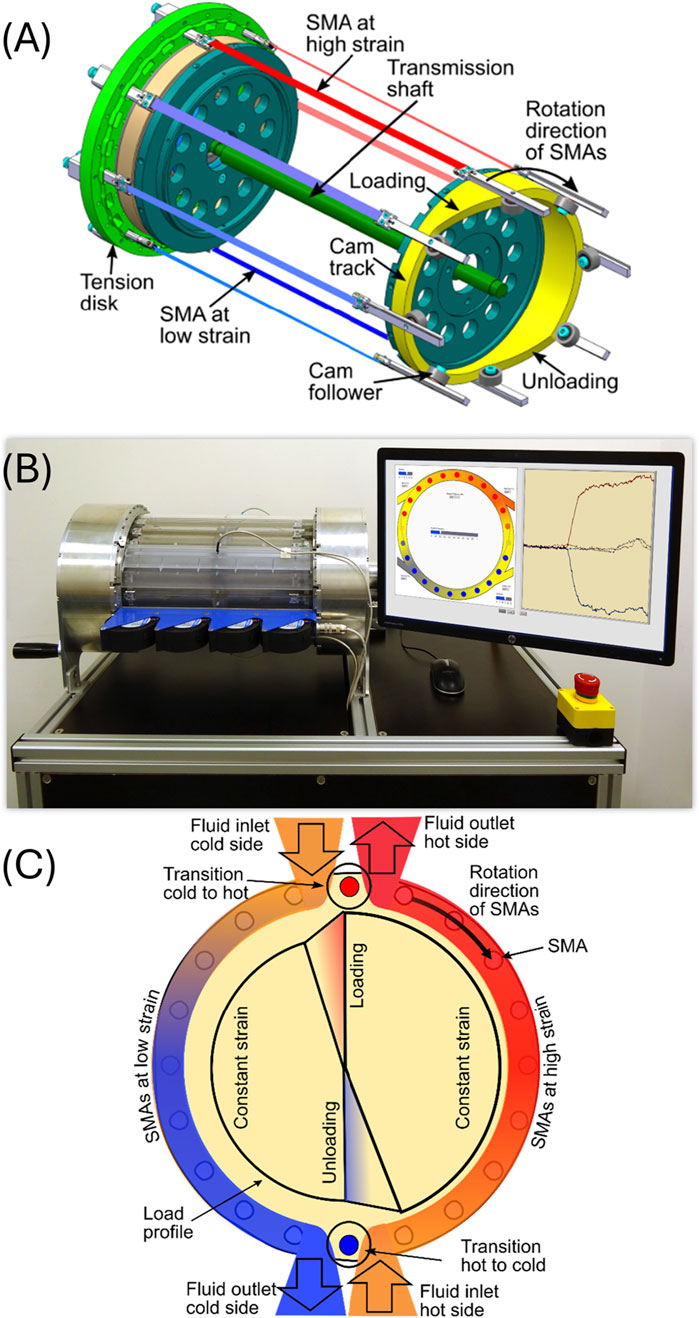
Figure 1. (A) First continuous working air to air elastocaloric demonstrator (Saarland University) (B) Schematic representation of the mode of operation (C) Schematic sectional view (Kirsch et al., 2018a; Welsch et al., 2018).
The channel’s outer shell is constructed from Plexiglas to allow visual observation of the rotation and the loading and unloading processes of the bundles within the channel. In this setup, the latent heat generated by the elastocaloric effect is supplied by elastocaloric sub-elements, with the capacity to house up to 24 of these elements. Each sub-element can bundle as many as 30 NiTi wires, each with a diameter of 200 µm. A critical aspect of the design is that the wires experience only linear loading. Rotational movement is transferred through rollers, which are constrained to translational motion by linear guide rails, while the cam track absorbs the resulting torsional forces. This mechanism enables the sub-elements to undergo controlled loading and unloading. To ensure optimal distribution of the latent heat, the bundles are arranged equidistantly along the diameter. However, the focus on the demonstrator and its measurement setup imposes certain limitations, which are explored in detail in the following chapter.
The current air-to-air system functions as a demonstrator. To increase performance, the available latent heat must be enhanced, which corresponds to increasing the amount of material. In the existing design, the number of bundles within the machine can only be increased by enlarging the diameter, provided that the spacing between the bundles remains constant. However, this additional volume cannot be fully utilized, as it accommodates the powertrain (see Figure 1). It is therefore essential to find a way to make this otherwise unused space functional through established principles. Innovative product development often follows two main approaches: technology push and market pull (Boyer and Kokosy, 2022; Dixon, 2001). Since elastocaloric technology represents a new advancement in cooling systems, the development methodology favors the technology push approach. This involves identifying applications where the technology provides clear advantages to users. While this approach carries some risk due to uncertain market demand, the potential benefits and competitive edge can outweigh it. Given the current performance of the system, it is particularly suited for mobile applications, such as cooling beverages or refrigeration of medicine. Many devices in these sectors rely on the Peltier effect, which offers lightweight and quiet operation. However, the efficiency of Peltier-based systems is relatively low (RS, 2025). In contrast, the NiTi material used in elastocaloric systems exhibits a high material coefficient of performance (COP) (up to 20 (Wieczorek et al., 2017)), enabling the development of efficient cooling solutions. COP (material) measures the cooling or heating efficiency. It is the ratio of useful cooling or heating energy (latent heat (
A can cooler has been identified as a viable use case for application-driven demonstration purposes. The beverage cooling system must be compact, ideally with a cubic shape to facilitate handling. The overall size should not exceed a 400 mm cube. The previously unused volume serves as the cooling chamber, designed to ensure continuous circulation of cold air over the wires and throughout the chamber. This continuous airflow enhances the cooling effect. Weight is another critical factor in mobile applications. Through the optimization of forces and the selection of lightweight materials, the illustrative and compact can cooler use-case system is developed by integrating several interconnected subsystems. The development process is elaborated in the following chapter.
The demonstrator depicted in Figure 1 serves as the foundation for the development of the new can cooler, referred to as the ECCube. By defining the use case through the technology push approach, the goal is to minimize the limitations of the existing system, while maximizing the advantages of elastocaloric technology within the ECCube. The progression from the first continuously operating air-to-air elastocaloric demonstrator to a fully functional prototype can be outlined in two fundamental steps:
• system simulation
• system design and fabrication
The machine’s architecture consists of three interconnected subsystems that interact with one another. A black box representation of these subsystems and their interactions is presented in Figure 2, serving as the foundation for the development process.
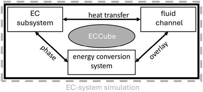
Figure 2. Black box representation of the ECCube.
The elastocaloric subsystems are NiTi wire bundles, which consist of thermomechanical elements made from NiTi in wire form, with a diameter of 200 µm. These wires provide the latent heat necessary for the cooling process. Bundling thin wires offers a significant advantage due to the improved surface-to-volume ratio, resulting in more efficient heat transfer.
The use of tensile loading in elastocaloric materials offers advantages such as reduced energy consumption and simplified system design. However, tensile loading promotes crack growth, which reduces the material’s lifetime. To address this issue, several measures can enhance long-term stability: reducing maximum strain levels minimizes material fatigue (Michaelis, 2020); pre-straining and cycling at plateau strain increases durability (Tušek et al., 2018); modifying material composition, such as adding copper to nickel-titanium alloys (Ossmer et al., 2016b), improves fatigue resistance; optimizing manufacturing processes, like sputtering thin films, enhances microstructure and homogeneity (Bechtold et al., 2012); and surface treatments reduce crack initiation and propagation (Tušek et al., 2018). Additionally, elastocaloric systems can be designed for periodic maintenance, allowing for the replacement or repair of degraded components to extend operational lifespan. The bundle principle used, allows for quick replacement of the 12 installed bundles with prefabricated and pre-trained bundles after the material’s lifespan, enabling simple maintenance. These measures are essential for developing sustainable elastocaloric cooling systems with improved reliability and durability.
These EC subsystem elements are manufactured through a winding process, as described in (Kirsch et al., 2023) and subsequently undergo a training phase.
The material undergoes 50 cycles of loading at a rate of 4
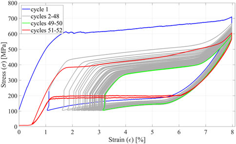
Figure 3. Stress-strain curve of the training process for a NiTi bundle of 30 wires with a diameter of 200 µm and a length of 150 mm. 50 cycles: loading at a rate of 4
The optimal strain for this system is capped at 6%. Further studies (Michaelis, 2020) indicate that utilizing internal hysteresis increases the heat absorbed by the material. Consequently, operating the material with an elongation between 2% and 6% is recommended for the ECCube. Thus, the region in which the bundles are subjected to load is similar to the one in which they were trained.
The ability to fine-tune the operating point must be factored into the mechanical design. To harness the latent heat generated, it must be transferred through a fluid channel—forming the second subsystem of Figure 2—allowing efficient heat transport. The system’s efficiency hinges on recovering this latent heat from the thermomechanical elements through an energy conversion mechanism, which necessitates a drive system. These two additional subsystems, the fluid channel and the energy conversion system (including the drive), are explored in the following chapters. Based on the use case, the objective is to cool a standardized can with a diameter of 52 mm and a height of 134 mm. To maximize the temperature change, the cooling chamber volume is minimized, thereby enhancing the cooling unit’s efficiency and reducing overall weight.
Before the ECCube is developed, a simulation tool developed by Felix Welsch (Welsch et al., 2018) is utilized to calculate the thermal and mechanical characteristics of an elastocaloric (EC) system. This tool is based on free energy models for shape memory alloys (SMA) and coupled with thermodynamic heat transfer. The system-level simulation tool integrates the mechanical drive kinematics, thermal values with fluid transport and multiple SMA wire models. Through input parameters such as the loading function of the cam track, rotation frequency, SMA arrangement, and flow rate, the torque, temperatures, and thus the mechanical and thermal power can be determined for all configurations. Detailed descriptions and data can be found in (Welsch et al., 2018). The model allows for the identification of all key parameters in an EC-system. Factors such as machine diameter, bundle length, rotation frequency, and fluid flow rate directly influence the system’s performance. The model employs NiTi wires with a 200 µm diameter, the same material and dimension intended for use in the ECCube. The bundles, designed to mimic real-world counterparts, consist of 30 wires each. Thermodynamics and fluid dynamic principles dictate that airflow and bundle rotation direction significantly affect heat exchange between the wires and air, impacting both adiabatic temperature change and the energy required to circulate air around the wires. Two configurations are considered: co-flow and counterflow.
• Co-flow: Airflow direction matches the rotation direction of the bundles, resulting in lower relative velocities and reduced energy input for air movement.
• Counterflow: Airflow direction opposes the rotation of the bundles, increasing relative velocities, enhancing heat transfer, and theoretically boosting thermal output. However, this setup demands greater energy to drive airflow.
To optimize efficiency, the co-flow principle is applied in the warm channel, where minimizing energy consumption is prioritized since thermal output from this channel is considered waste heat. Conversely, the counterflow principle is implemented in the cold channel, maximizing useful cooling performance. These considerations are integrated into the simulation, with airflow parameters adjusted accordingly. Results are shown in Figure 4 and discussed in detail in (Ehl et al., 2024).
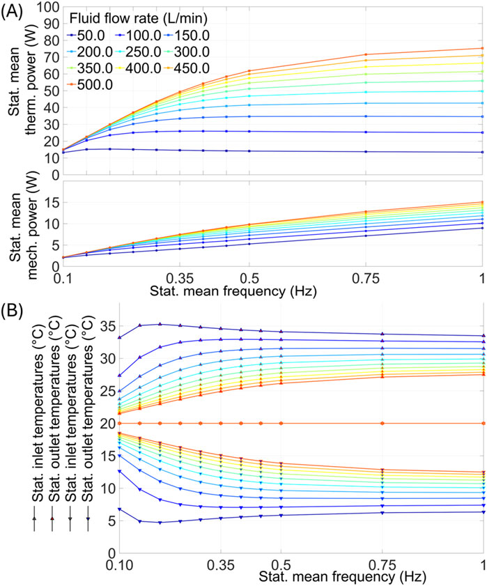
Figure 4. Parameter study: (A) mechanical and thermal power (B) temperature output with different rotation frequency and fluid flowrate (Ehl et al., 2024).
A balance between thermal output and mechanical energy input is achieved at a bundle rotation frequency of 0.5 Hz, ensuring low force levels, in line with design requirements. At an airflow rate of 200 L/min, the simulated EC-system can generate 34.8 W of thermal power and achieve a temperature differential of 8.7 K from cold inlet and outlet (see Figure 1C). This results in a COP of 5.8.
The simulation results presented in Table 1 represent the best-case scenarios with a counterflow configuration. However, the electrical power required to generate the airflow is not included in this calculation. This is highly dependent on the fans used and the specific channel geometries, which must first be determined for the CanCooler. Besides this, it is important to note that the simulation model does not take potential bypass flows into account, as the specific factors causing bypassing in the Can-Cooler have not yet been identified. Cam geometry design must account for expansion rates, as addressed in (Schmidt et al., 2016). A cam diameter of 150 mm is necessary to house the can and arrange 12 bundles around it, ensuring evenly distributed spacing along the cam’s perimeter. The final system specifications are summarized in the following categories shown in Table 1.
• material data
• system data
• system output
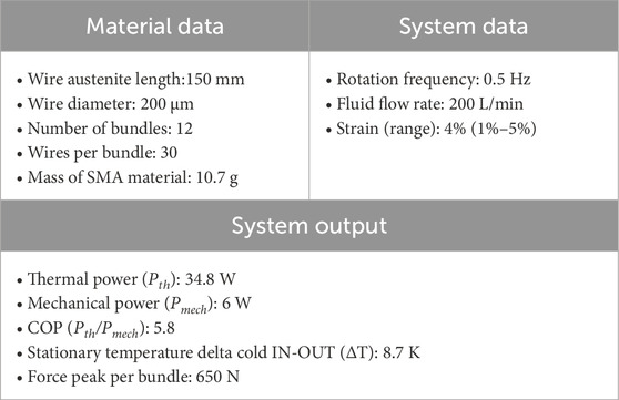
Table 1. Material data, system data and system output of the ECCube.
The volume to be cooled, excluding the channel in which the bundles move, is approximately 0.75 L. It is important to note that no thermal load was applied within the chamber during the simulation. Consequently, the theoretical simulated volumetric cooling density could reach 464 W m–3.
As shown in Figure 2, the development of the ECCube requires the design of both a fluid system and a mechanical concept. This chapter focuses on the development of these two systems, incorporating the results from the simulation into the process.
The dominant heat transfer mechanism in the case of the CanCooler is forced convection caused by moving air. The heat released to the air during cooling can be determined using Newton’s law of cooling, as described by Equation 1:
where
The heat transfer can be enhanced by increasing the temperature difference, such as raising the wire temperature, and ensuring continuous heat removal to a heat sink within the chamber. The heat transfer coefficient (
where
The thermal conductivity of the fluid, flow velocity, and specific heat capacity significantly influence heat transfer. A comparison of thermal conductivities shows that using helium increases thermal conductivity approximately 7 times compared to air, while hydrogen achieves similar results (Schweizer, 2025b). Using water increases thermal conductivity by a factor of 23 (Schweizer, 2025a). Alcohols like ethanol show an increase of about 6.7 times compared to air (Schweizer, 2025a). Additionally, adding nanoparticles to water can significantly enhance thermal conductivity. For instance, a concentration of less than 0.12% CU nanoparticles in water doubles its thermal conductivity (Abbasi, 2019).
The arrangement of the wires in the air channel significantly influences heat transfer. As shown in (Welsch et al., 2023), altering the angles within the bundle leads to an increase in the heat transfer coefficient of the bundle. All these findings are incorporated into the development process of the CanCooler.
The system, as outlined in the “Use cases development: ECCube” chapter, is designed to cool a standard can. In contrast to the existing demonstrator system, the cold side will feature continuous air circulation, while warm exhaust air will be vented.
The CanCooler operates with air as the cooling medium despite the significantly higher heat capacities of liquids or other gases. This choice is due to two main reasons. First, the can is intended to be cooled directly by the air passing over the wires, which simplifies the cooling process and avoids additional intermediate cooling steps. Second, sealing systems for liquids or gases like helium are far more complex compared to air-based systems, as they require preventing any leakage into the surrounding environment. This complexity increases both design and maintenance efforts. Additionally, using particles in the cooling medium would further complicate the fluid management system, requiring more advanced designs and increased construction effort. Air cooling, therefore, offers a simpler and more practical solution for the CanCooler system.
The duct requirements are as follows:
• Low overflow–minimize air leakage between hot and cold channel to maintain efficiency.
• Optimal airflow around the wires–ensure effective airflow around the wires to maximize heat exchange.
• Cooling chamber
◦ Ensure optimal airflow around the can.
◦ Enable continuous air circulation within the chamber.
• Efficient heat dissipation–facilitate effective heat removal from the warm side.
• Low fan back pressure–allow the use of standard fans, commonly applied in the IT sector.
The final point ensures compatibility with proven fan technology. CFD (Computational Fluid Dynamics) simulations (Comsol©) indicate that in ducts of the same height, maximum pressures of 20 Pa (≈2 mmH2O) occur at the narrowest point. As a result, only standard 40
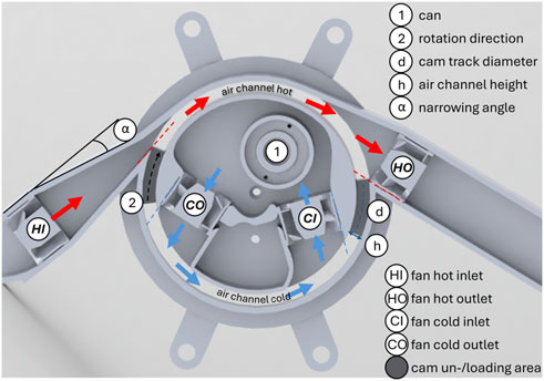
Figure 5. 2D representation of the ECCube’s air channel.
To optimize efficiency, the counterflow principle will be applied to the cold side channel, while co-flow is used for the hot channel. In a 2D view, two fans are positioned within the chamber plane to ensure optimal air circulation around the can.
The design concept of the inner tube is depicted in Figure 5. An internal chamber with a diameter of approximately 145 mm is available, which must accommodate the can and two fans. The CI fan (Cold In) draws air past the wires into the chamber, directing it to flow around the can. The CO fan (Cold Out) extracts the air from the chamber and re-accelerates it before it interacts with the wires. In Figure 5, arrows illustrate the direction of airflow.
The fans in both channels operating under the push-pull principle to achieve greater air velocities within the ducts. The FDM 3D printing process is particularly suitable for manufacturing this complex structure. The internal geometry of the 3D print inherently provides a degree of insulation for the chamber, enhancing thermal performance. The used material is PETG with a thermal conductivity of 0.2 W m−1 K−1 (König GmbH Kunststoffprodukte, 2025). Figure 5 also illustrates the outer air duct, which is designed to channel warm air. This duct functions according to the co-flow principle alongside the wires. The outer duct must also fulfill the requirement of housing the EC system and guiding air out of the enclosure. As with the inner duct, a 2D representation is first considered. The HI fan (Hot In) is employed to draw in ambient air. To achieve optimal air acceleration, the supply duct is adapted to a cross-section width of 9.5 mm. This narrowing adheres to flow theory rules for gradual constriction, with a maximum angle of α ≤ 8° to avoid edge separation and ensure uninterrupted airflow.
The fan is positioned to align the airflow with the duct direction. The airflow catches the bundles directly behind the cam, allowing effective cooling, indicated by the red dashed line in Figure 5. The HO fan (Hot Out) does not have a duct construction before it, allowing unrestricted outflow and preventing backflow into the narrow cold-side duct.
This arrangement is supported by the fan drawing air outward, and its edge is configured to ensure air circulates around the full holding phase of the cam, maximizing heat exchange, as also shown by a red dashed line. Externally, the duct walls are oriented to direct airflow efficiently towards the duct. The airflow vectors depicted in Figure 5 show parallel alignment with the duct’s vectors. The vectors of the HI and CO fans, although pointing in opposite directions, have similar magnitudes, theoretically canceling each other out and reducing overflow. Complete prevention of overflow is not possible due to the non-hermetic connections of the ducts and the rotating wires. To ensure homogeneous airflow around the entire length of the bundles, four fans are stacked vertically, as illustrated in Figure 6. These fans are PWM-controllable, allowing for theoretical individual speed adjustments along the stack for optimized control. Temperature sensors are essential for both validation and control purposes. Their arrangement is illustrated in Figure 6. This configuration enables the generation of a temperature profile across the cross-section of the chambers. A detailed explanation of the temperature measurement methodology and the sensor arrangement is provided in the chapter 4.1.
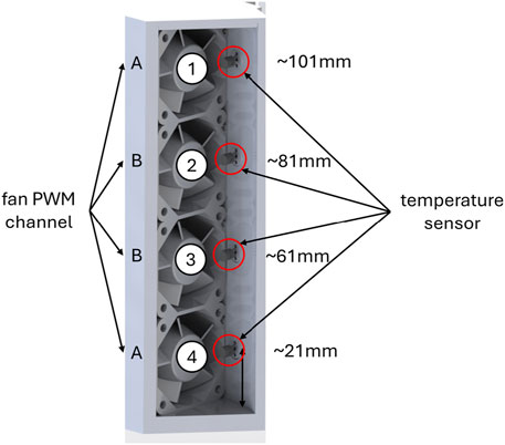
Figure 6. Hot channel inlet: 4
The mechanical concept consists of the energy conversion unit and the associated drive system. This unit must also be assembled in a basic framework. The development of the drive system and the framework is described in more detail in the following chapters.
The drive system consists of the energy conversion unit and the associated drive concept. For this prototype, a material mix is employed, combining plastics produced through FDM 3D printing and metals, with the choice of materials dictated by the mechanical loads. Due to the design of the previously developed inner air duct, a centrally located powertrain is not feasible. Consequently, the drive system must be relocated to the outer periphery.
A belt drive is selected as the driving mechanism, offering the following advantages:
• Transmission capability via gear wheels.
• Synchronous driving of both ends of the bundles, which is essential since the bundles are not torsional rigid.
• Synchronization is achieved using a coupling rod that drives both belts.
Following the determination of the drive type, the loading and unloading mechanism for the bundles is designed, along with the energy conversion system. Key parameters from the simulation and the patented cam approach are summarized as follows:
• Maximal peak load on structure during mechanical loading per bundle: 650 N.
• Number of bundles: 12.
• Cam specifications: 30-degree cam with a 9 mm stroke.
The cam is responsible for the continuous rotational loading and unloading of the bundles.
The bundles, as shown in Table 1, are composed of 30 wires with a diameter of 200 µm each. As explained earlier, a larger surface-to-volume ratio leads to higher heat transfer coefficients. A smaller wire diameter would enable this; however, to accommodate the same amount of material in the system, more bundles would need to be included, which would increase the overall size of the system. Therefore, a diameter of 200 µm is considered a suitable choice. Changing the angle of the bundles involves significant effort to ensure that the construction operates flawlessly in continuous operation. For this reason, this measure will not be implemented during the first development stage.
Due to the cam’s shape, the rollers attached to the guide rails exert forces in both the Y and X directions. Consequently, the brackets for the linear guides must be designed to absorb these lateral forces in the X direction. The 12 guide rails (Figure 7 (7,7a-e)) are symmetrically mounted on a polygon with 12 corners (Figure 8; (10)). Given the constrained spatial conditions, the guide carriages are minimized in size to optimize the available space. This guide rail system, driven by the belt drive (Figure 7 (2 and 6)), incorporates a gear wheel firmly (Figure 8; (12))) connected to the polygon. This configuration is referred to as the loading unit, as shown in Figure 7. The proposed drive system ensures efficient, synchronized motion of the bundles while accommodating the spatial and mechanical constraints of the design.
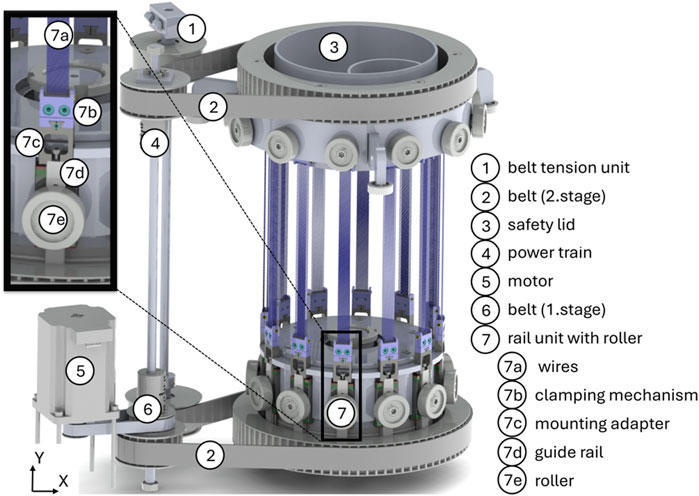
Figure 7. CAD-model of the loading unit and the drive system.
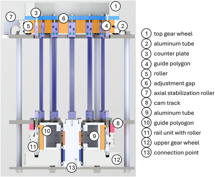
Figure 8. CAD-model in sectional view of the loading unit and counter bearing.
The gear wheel (Figure 8 (12)) and the polygon (Figure 8 (10)) are manufactured using ABS through a 3D printing process, which allows for precision and flexibility. To ensure the polygon can absorb lateral forces in the X-direction, it is reinforced with an inner ring (Figure 8 (9)). This inner ring is made of aluminum, a material chosen for its low production cost and sufficient strength to stabilize the overall assembly. The entire unit, comprising the gear wheel, polygon, and inner ring, is centrally mounted below the cam (Figure 8 (13)) to ensure precise alignment and efficient operation. A sectional view of the loading unit, as shown in Figure 8, illustrates the integration of these components and their alignment with the cam mechanism. The rollers (Figure 8 (7a)) are designed to move smoothly along the cam track (Figure 8 (8)), The opposite end of the assembly, referred to as the counter bearing, is also reinforced to absorb the tensile forces in the Y-direction. The counter bearing is rotationally supported by 12 rollers (Figure 8 (5)).
For axial stabilization, three rollers (Figure 8 (7)) are evenly spaced around the circumference.
The load-bearing components of the counter bearing are constructed from metal. Meanwhile, the guide polygon (Figure 8; (4)), are manufactured from ABS plastic. Additionally, a plastic gear wheel (Figure 8 (1)) is affixed to this unit to drive the belt mechanism, as illustrated in Figure 7. The sectional view in Figure 8 reveals a gap between the bundles and the counter plate (Figure 8 (6)). This gap facilitates the adjustment of the operating point described earlier. The belt drive system, along with the coupling axle, is shown in Figure 7 (4). A belt tensioning unit (Figure 7 (1)) is integrated to maintain proper belt tension. The two-stage belt (Figure 7 (2 and 6)) transmission achieves a transmission ratio of approximately 11, enabling the use of a single motor (Figure 7 (5)) with a torque of around 3 Nm. To ensure operational safety, a safety cover (Figure 7 (3)) is incorporated into the design. This cover protects the access opening to the cooling chamber from the rotating components. This feature enhances safety while maintaining the functional integrity of the system.
The basic framework is designed to securely fix the cam, allowing the rollers of the loading unit to move smoothly over it. The framework is constructed from three steel plates, as illustrated by the outer structure of the prototype core in Figure 9. The top plate (Figure 9 (3)) supports the counter bearing (Figure 9 (1)), provides a smooth surface for the 12 rollers (Figure 8 (5)) to travel on. Same is for the outer shell and the guide arms (Figure 9 (2)). The middle plate (Figure 9 (6)) holds the patented cam track (Figure 8 (8)). Stabilization is achieved through threaded rods encased in steel tubes (Figure 9 (4)), which connect these plates. Between the cam mounting plate and the base plate (Figure 9 (8)), the loading unit (Figure 9 (7)) is inserted. The base plate incorporates a shaft, which centers the loading unit via bearings within the cam, enabling smooth rotational motion. This relationship is further detailed in Figure 8. The base plate is connected to the other two plates using the threaded rods, Furthermore, the base plate serves as the mounting point for securing the demonstrator within its housing. This robust design ensures mechanical stability and smooth operation, fulfilling both the structural and functional requirements of the system.
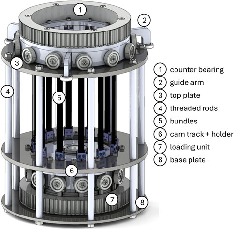
Figure 9. CAD-model of the basic framework including the counter bearing and the loading unit.
The realization of the first prototype of the ECCube can be seen in Figure 10. The framework and the energy conversion unit including the drive are mounted in a housing made of aluminum profiles, which are encased in Plexiglas. The system can be controlled by a tablet connected via bluetooth. A display provides insight into the temperature status in the chamber.
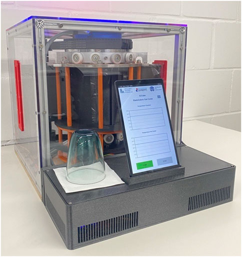
Figure 10. First prototype realization of the ECCube.
Once the ECCube has been assembled, its functionality is verified, including the ability to control the rotational speed of the bundles and fan speeds (volume flow) during operation based on temperature data. This capability will enable rapid cooling of the chamber upon system startup, followed by efficient machine operation maintaining the target temperature. The implementation of the control system is not part of this paper and will only become relevant for future applications. To achieve this, a measurement setup incorporating 24 temperature sensors is realized. These sensors provide precise thermal data, facilitating real-time adjustments to the system’s operating parameters. Details of this setup and the resulting performance is discussed in the following chapters.
The measurement setup for the ECCube is realized with an ESP32 microcontroller, which allows data acquisition during operation to enable temperature-dependent feedback control. The DS18B20 series temperature sensors from Dallas Semiconductor are application (Semiconductor, 2025). These sensors are specifically designed for direct evaluation with microcontrollers and provide the following key features:
• Accuracy: ±0.5°C within a range of −10°C to +85°C.
• Resolution: 12-bit, providing a precision of ±0.0625°C.
• “OneWire” Evaluation: Enables simplified cabling, allowing multiple sensors to connect to a single data line. Each sensor is equipped with a unique ID, ensuring proper differentiation between sensors.
The “OneWire” protocol significantly reduces cabling complexity. By using a single data line for multiple sensors, this setup achieves a streamlined and efficient configuration. The DS18B20 sensor datasheet does not specify a required orientation for installation. To minimize the influence on airflow, the sensors are aligned with their rounded sides facing the flow direction. This arrangement reduces aerodynamic disruption while ensuring accurate temperature readings. Figure 6 demonstrates the sensor arrangement along the axis of rotation. A total of six measurement points is implemented, each positioned at the same vertical height, as illustrated in Figure 11. The sensors are identified with green squares in Figure 11 to indicate their placement. The warm side measurement points are strategically placed to capture key temperature changes within the system. The first measurement point is located upstream of the HI, where the ambient temperature is recorded. This provides a baseline for assessing thermal changes as the air moves through the warm duct.

Figure 11. (A) 2D representation measuring points (B) Picture of the measuring setup.
The second measurement point is positioned downstream of the wires but still within the warm duct. Here, the sensor measures the temperature of the air after it has been heated by the wires. Its placement ensures the sensor remains unaffected by the rotating bundles, which could cause damage. The third measurement point is located downstream of the HO. At this location, the sensor records the total heat absorbed by the air within the warm duct. This measurement serves as an indicator of the system’s thermal efficiency. The temperature recorded at the HO exit point should be higher than the temperature before the HI. If this is not observed, it suggests temperature exchange between the warm and cold ducts, either due to warm air escaping into the cold duct or cold air infiltrating the warm duct. However, the current measurement approach does not differentiate between these two scenarios.
To optimize the measurement of the cold chamber, sensors are placed at both the inlets and outlets. The temperature difference between these points provides insight into the amount of heat transferred to the air within the chamber. Specifically, the difference between the outlet and inlet temperatures indicates the extent of heat absorbed from the air by the wires during the holding phase. To analyze the temperature distribution around the can, a specialized “measuring can” has been developed. This can is equipped with four sensors mounted externally at the same height as other measuring points in the chamber. The can is designed to rotate in 12-degree increments, allowing for a detailed mapping of temperature variations within the chamber at multiple angular positions. This is a simple gear system that can be manually adjusted and secured with a screw. Includes the designations for each measuring point, which will serve as the standard nomenclature in subsequent section.
The complete setup is shown in Figure 11B. The storage of the measurement data for this study is realized using a Python script. The ESP32 microcontroller requires 5,000 ms to read data from the 24 sensors and transfer it via the serial port, resulting in a sampling rate of 0.2 Hz. During operation, the ESP32 processes the data to control the rotation frequency and fan speed directly. The fans are controlled individually using PWM signals generated by the ESP32.
For the initial verification of the ECCube’s functionality, four measurement series are conducted (see Table 2). By leveraging the ability to control the fans individually, the outer fans Figure 6 (1) and (4) are operated at a reduced speed compared to the inner fans. This adjustment results in a slower airflow on the outer regions, minimizing the leakage of air through areas that remain unsealed due to the rotating components within the system. The distinction between the middle and outer fans is illustrated in Figure 6. The experimental data for this verification is summarized in the following table:
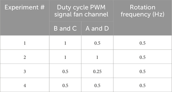
Table 2. Experimental parameters overview.
In all experiments, the rotation frequency and the PWM of the fans remain unchanged. The selected rotation frequency of 0.5 Hz, in combination with the installed cam, allows adiabatic loading and unloading of the wires. By varying the duty cycle of the PWM signal for the fans, an optimal configuration of volume flow to rotation frequency is determined, allowing the wires to exchange their entire heat with the medium. The measured start temperature at the HI is 295.15 K. For each measurement, this can be considered as the ambient and system temperature.
In evaluating the temperature results, the sensor nomenclature is based on the labeling presented in Figure 6. Sensor number 1 corresponds to the sensor located at the top of the air channel, while sensor number 4 represents the sensor positioned at the bottom of the channel. The orientation of the “measuring can” follows the configuration depicted in Figure 11. The temperature values are presented as differences, with each test conducted over a duration of 600 s. While the primary focus of the evaluation is on the cold side, a brief analysis of the warm side yields valuable insights. Figure 12 illustrates the temperature differences between the HOT IN and HOT OUT measurement points for all four tests. Across all sensors, the temperature levels are observed to be similar, indicating minimal variation along the length of the bundles. It is evident that latent heat from the wires is effectively dissipated, with saturation occurring uniformly across all cases at approximately 100 s. This indicates that the system reaches thermal equilibrium, and no additional heat can be extracted from the wires beyond this point. After the 100 s in Figure 12B, the difference is getting smaller, which can be attributed to changes in the inlet or outlet temperature. However, due to the laboratory’s climate control system, any increase in the inlet temperature is negligible. Consequently, a decrease in the outlet temperature must be responsible for this behavior. A possible explanation is that the bundles on the cold side may not have fully released their heat and have not yet returned to the desired temperature. To confirm this hypothesis, further parameter sweeps are necessary for a detailed analysis.
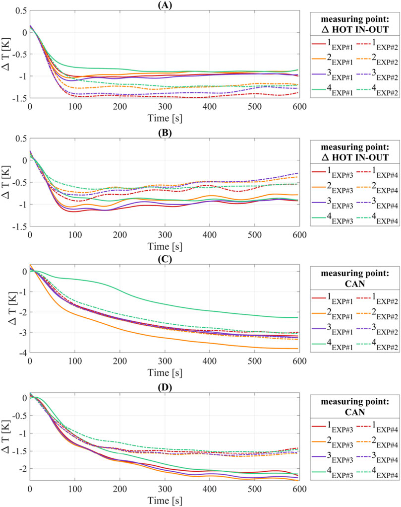
Figure 12. Temperature results HOT IN–OUT: (A) experiment 1 and experiment 2; (B) experiment 3 and experiment 4 (B) - Temperature results CAN: (C) experiment 1 and experiment 2; (D) experiment 3 and experiment 4.
A notable observation is the significant variation in saturation temperatures depending on the fan configurations. The configuration in which all fans operate at maximum speed demonstrates the highest level of heat dissipation. However, determining whether this configuration is optimal for the ECCube’s process control requires further analysis of the cooling chamber data. The analysis now shifts to the cold side, with particular focus on the temperature values at the CAN measurement point. Figures 12C, D presents the results of all four tests.
A clear pattern emerges, most of the curves are closely aligned, with larger deviations observed primarily in the first test. This trend is consistent across other measuring points within the cold chamber, such as those illustrated in Figure 13. A comparison of the chamber temperatures under different fan configurations highlights the impact of fan speed on the minimum achievable temperature. Specifically, experiments 3 and 4, shown in Figure 12D demonstrate that using a fan configuration with varying speeds for the middle and outer fans results in significantly greater heat dissipation within the chamber. Comparing experiments 2 and 4 Figures 12C, D further reveals that higher fan speeds—and consequently, higher air volume flow—can achieve lower temperatures within the chamber. However, this also indicates that the balance between fan speed and air velocity is suboptimal in experiment 4, whereas experiment 2 demonstrates a more favorable balance. Further testing is required to identify the optimal combination of fan speed and air velocity for achieving the most efficient cooling performance. Figures 13A, B illustrates the temperature differences between the COLD OUT and COLD IN measuring points. Across all tests, the temperature difference is negative, signifying heat transfer from the wires to the air. As the tests progress, the temperature differences approach saturation, indicating that the latent heat of the wires has largely dissipated from the air. This statement applies to this specific combination of flow rate and rotational frequency.
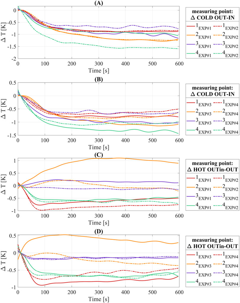
Figure 13. Temperature results COLD OUT–IN: (A) experiment 1 and experiment 2; (B) experiment 3 and experiment 4 - Temperature results HOT OUTin–OUT: (C) experiment 1 and experiment 2; (D) experiment 3 and experiment 4.
By the conclusion of each experiment, equilibrium is reached, where only a minimal amount of heat continues to be released into the chamber. This behavior aligns with the results shown in Figure 12, where the chamber temperature also stabilizes toward the end of the experiments. The analysis of fan combinations in Figure 12 applies similarly here. Specifically, configurations with slower outer fans outperform others at lower fan speeds, enhancing efficiency. These consistent results validate the accuracy of the temperature measurements. Importantly, in all tested fan configurations, at least 1 K of temperature delta is consistently extracted from the wires and transferred to the air. This confirms the effectiveness of the system in dissipating heat under various conditions.
The HOT OUT IN and HOT OUT measuring points are particularly relevant for analyzing the overflow within the system. As described in the chapter 4.1 this overflow can be evaluated by calculating the temperature differences between these points. Figures 13C, D displays these differences for all four experiments. The data clearly indicates that the sensors located at the upper and lower edges of the channel show significantly greater temperature differences compared to the other two sensors in all tests. This suggests that the airflow dynamics at these positions contribute to a larger temperature gradient. The observed discrepancies in levels among the sensors can likely be attributed to varying airflow patterns within the duct. Despite these variations, the consistent trend of overflow at the two outer sensors is evident. Importantly, the temperature difference for these sensors is less than zero, indicating that the temperature at the outer measuring points is higher. This implies that either warm air is escaping from the system or cold air is infiltrating, as previously hypothesized. Comparing experiments 1 and 2 Figure 13C further demonstrates that different fan configurations significantly affect the airflow and, consequently, the overflow behavior. These findings highlight the importance of optimizing fan combinations to minimize unwanted overflow and improve system efficiency.
A closer examination of the data from Sensor 2 in Figures 13C, D reveals differences compared to the other sensors. A possible explanation for the reduced overflow in this section could be the distinct airflow in this specific area, which may result from the fan voltage settings. In both cases with the other fan voltage settings (dotted line), there is also initially less airflow, but this changes over the course of the measurement and aligns with the other curves. A potential reason for this change could be a variation in airflow caused by temperature fluctuations. Further investigations with additional parameters are required to confirm these explanations.
In summary, the ECCube has demonstrated the ability to effectively cool the chamber containing the can. The unused space within the ECDemo has now been efficiently utilized resulting in a compact descriptive demonstrator system. Temperature differences of approximately 3.5 K were achieved within the cooling chamber. The expected value from the simulation of 8.7 K was not achieved. The losses present in the system were initially not considered in the simulation. The actual losses result from the previously described overflow at the interfaces between the warm and cold channel sides, as well as the imperfect sealing of the chamber and at the moving parts within the ECCube. Additionally, the insulation of the channel structure can be further improved. As a result, the real outcomes can be aligned with the simulation through sealing and insulation measures. The COP calculated using the simulation tool is 5.8. However, with the current setup, determining the actual COP of the ECCube is not feasible. Accurate determination of the COP requires measurement data for the volumetric flow rate, which necessitates enhancements to the existing test setup and will be conducted in a next step. Using the measurement setup, the can cooler can be efficiently operated through PWM control and adjustments to the rotation frequency. However, the impact of varying fan speeds along a row still requires further verification through additional measurements. These future investigations will help optimize the system’s cooling performance. With these results, a control system can be implemented for the upcoming application. Further measurements are required to advance the development and validation of the ECCube. To enhance evaluation and validation, determining the volume flow generated by the fans is essential. This data will enable the calculation of the thermal performance of the system. Additionally, a parameter sweep should be conducted, combining variations in rotation frequency with different fan speeds. This will allow identification of the optimal operating point for both rapid cooling of the chamber and efficient temperature maintenance. It is also necessary to examine the extent of air leakage from the channels at the rotating sides and address this issue through sealing measures. For prolonged operation in non-laboratory environments, the chamber must be insulated. Developing appropriate insulation concepts remains an outstanding task that requires attention.
The datasets presented in this article are not readily available because Confidential. Requests to access the datasets should be directed to Lukas Ehl: bHVrYXMuZWhsQHVuaS1zYWFybGFuZC5kZQ==.
LE: Writing–original draft, Writing–review and editing. NS: Conceptualization, Project administration, Writing–review and editing. DZ: Formal Analysis, Writing–review and editing. IT: Validation, Writing–review and editing. PM: Investigation, Writing–review and editing. S-MK: Supervision, Writing–review and editing, Resources. FL: Writing–review and editing, Investigation. PM: Resources, Supervision, Writing–review and editing.
The author(s) declare that no financial support was received for the research, authorship, and/or publication of this article.
The authors are grateful to Susanne-Marie Kirsch and Felix Welsch from the Intelligent Materials Systems Lab for their previous work on EC-system design and modeling and for the continuous help and guidance. We thank the company Ingpuls for providing the NiTi material and we thank the CASMART mentors of the student Design challenge for their helpful input and guidance. The authors acknowledge the use of OpenAI’s ChatGPT for language editing of this manuscript.
The authors declare that the research was conducted in the absence of any commercial or financial relationships that could be construed as a potential conflict of interest.
The author(s) declare that Generative AI was used in the creation of this manuscript. OpenAI’s GPT-4.
All claims expressed in this article are solely those of the authors and do not necessarily represent those of their affiliated organizations, or those of the publisher, the editors and the reviewers. Any product that may be evaluated in this article, or claim that may be made by its manufacturer, is not guaranteed or endorsed by the publisher.
Abbasi, S. (2019). The thermal conductivity modeling of nanofluids involving modified Cu nanorods by Ag nanoparticles. Heat. Mass Transf. 55 (3), 891–897. doi:10.1007/s00231-018-2476-2
Ahčin, Ž., Dall’Olio, S., Žerovnik, A., Už, B., Porenta, L., Kabirifar, P., et al. (2022). High-performance cooling and heat pumping based on fatigue-resistant elastocaloric effect in compression. Joule 6 (10), 2338–2357. doi:10.1016/j.joule.2022.08.011
Ahčin, Ž., and Tušek, J. (2023). Parametric analysis of fatigue-resistant elastocaloric regenerators: tensile vs. compressive loading. Appl. Therm. Eng. 231, 120996. doi:10.1016/j.applthermaleng.2023.120996
Bachmann, N., Fitger, A., Maier, L. M., Mahlke, A., Schäfer-Welsen, O., Koch, T., et al. (2021). Long-term stable compressive elastocaloric cooling system with latent heat transfer. Commun. Phys. 4 (1), 194. doi:10.1038/s42005-021-00697-y
Bechtold, C., Chluba, C., Lima De Miranda, R., and Quandt, E. (2012). High cyclic stability of the elastocaloric effect in sputtered TiNiCu shape memory films. Appl. Phys. Lett. 101 (9), 091903. doi:10.1063/1.4748307
BGR (2014). Mineralische Rohstoffe - Rohstoffwirtschaftlicher Steckbrief für Titan. Available online at: https://www.deutsche-rohstoffagentur.de/DE/Themen/Min_rohstoffe/Downloads/rohstoffsteckbrief_ti.pdf.
BGR (2025). Deutsche rohstoffagentur - nickel. Available online at: https://www.deutsche-rohstoffagentur.de/DERA/DE/Aktuelles/rohstoff_Nickel.html.
Borzacchiello, A., Cirillo, L., Greco, A., and Masselli, C. (2023). A comparison between different materials with elastocaloric effect for a rotary cooling prototype. Appl. Therm. Eng. 235, 121344. doi:10.1016/j.applthermaleng.2023.121344
Boyer, J., and Kokosy, A. (2022). Technology-push and market-pull strategies: the influence of the innovation ecosystem on companies’ involvement in the Industry 4.0 paradigm. J. Risk Finance 23 (5), 461–479. doi:10.1108/jrf-12-2021-0193
Bruederlin, F., Bumke, L., Chluba, C., Ossmer, H., Quandt, E., and Kohl, M. (2018). Elastocaloric cooling on the miniature scale: a review on materials and device engineering. Engineering 6 (8), 1588–1604. doi:10.1002/ente.201800137
Cheng, S., Sun, W., Li, X., and Zhang, J. (2024). Elastocaloric effect and cooling performance of NiTi sheets in a continuous rotating bending elastocaloric cooler. Apl. Mater. 12 (8), 81116. doi:10.1063/5.0217563
Cirillo, L., Greco, A., and Masselli, C. (2023). Development of an electronic circuit cooling system using elastocaloric effect: a FEM comparison among different configurations. Appl. Therm. Eng. 219, 119463. doi:10.1016/j.applthermaleng.2022.119463
Cirillo, L., Greco, A., and Masselli, C. (2024). The energy performances of an elastocaloric device for air conditioning through numerical investigation. Appl. Therm. Eng. 236, 121517. doi:10.1016/j.applthermaleng.2023.121517
Defay, E., Crossley, S., Kar-Narayan, S., Moya, X., and Mathur, N. D. (2013). The electrocaloric efficiency of ceramic and polymer films. Adv. Mater. 25 (24), 3337–3342. doi:10.1002/adma.201300606Available online at: https://europepmc.org/article/med/23666863.
Dixon, J. C. (2001). The “market pull” versus “technology push” continuum of engineering education. 2001 Annual Conference, Albuquerque, New Mexico. doi:10.18260/1-2--9531
Ehl, L., Scherer, N., Zimmermann, D., Molitor, P., Trofimenko, I., Louia, F., and Motzki, P. (2024). ECCube - small scale elastocaloric cooling demonstrator. Proceedings of ASME 2024 Conference on Smart Materials, Adaptive Structures and Intelligent Systems, SMASIS2024. doi:10.1115/SMASIS2024-140329
Fähler, S., Rößler, U. K., Kastner, O., Eckert, J., Eggeler, G., Emmerich, H., et al. (2012). Caloric effects in ferroic materials: new concepts for cooling. Adv. Eng. Mater. 14 (1–2), 10–19. doi:10.1002/adem.201100178
Frenzel, J., Wieczorek, A., Opahle, I., Maaße, B., Drautz, R., and Eggeler, G. (2015). On the effect of alloy composition on martensite start temperature and latent heats in NiTi based shape memory alloys. Acta Mater. 90, 213–231. doi:10.1016/j.actamat.2015.02.029
Goetzler, W., Zogg, R., Young, J., and Johnson, C. (2014). Energy savings potential and RD& D opportunities for non-vapor-compression HVAC technologies. Available online at: https://www.energy.gov/sites/prod/files/2017/12/f46/bto-DOE-Comm-HVAC-Report-12-21-17.pdf.
Hou, R., Xiao, F., Wu, S., Zhai, X., Lin, Z., Cai, X., et al. (2024). Continuous operating elastocaloric air-cooling device. The Innovation Energy, 1(2):100026, doi:10.59717/j.xinn-energy.2024.100026
Ianniciello, L., Bartholomé, K., Fitger, A., and Engelbrecht, K. (2022). Long life elastocaloric regenerator operating under compression. Appl. Therm. Eng. 202, 117838. doi:10.1016/j.applthermaleng.2021.117838
IPCC (2021). Zusammenfassung für die politische Entscheidungsfindung. In: Naturwissenschaftliche Grundlagen. Beitrag von Arbeitsgruppe I zum Sechsten Sachstandsbericht des Zwischenstaatlichen Ausschusses f¨r Klimaänderungen. Editors V. Masson-Delmotte, P. Zhai, A. Pirani, S.L. Connors, C. Péan, S. Berger et al.
Kirsch, S. M., Welsch, F., Ehl, L., Louia, F., Seelecke, S., and Motzki, P. (2023). Systematic thermo-mechanical validation of numerous tensile-loaded NiTi wire bundles used for elastocaloric heating and cooling. Am. Soc. Mech. Eng., 1–8. doi:10.1115/SMASIS2023-110889
Kirsch, S. M., Welsch, F., Michaelis, N., Schmidt, M., Schütze, A., and Seelecke, S. (2018b). Continuously operating elastocaloric cooling device based on shape memory alloys. Darmstadt, Germany: Development and Realization - Poster, 16–20.
Kirsch, S. M., Welsch, F., Michaelis, N., Schmidt, M., Wieczorek, A., Frenzel, J., et al. (2018a). NiTi-based elastocaloric cooling on the macroscale: from basic concepts to realization. Energy Tech. 6, 1567–1587. doi:10.1002/ente.201800152
Kirsch, S. M., Welsch, F., and Seelecke, S. (2016). Energiewandler mit thermodelastischer Anordnung sowie Energiewandlersystem. DE102016118778.3 patent-pending. Germany.
Kitanovski, A., Tušek, J., Tomc, U., Plaznik, U., Ožbolt, M., and Poredoš, A. (2015). Magnetocaloric Energy Convers. 179 (Mcm), 167–210. Available online at: http://www.scopus.com/inward/record.url?eid=2-s2.0-84921450710&partnerID=tZOtx3y1. doi:10.1007/978-3-319-08741-2_5
König GmbH Kunststoffprodukte (2025). Technisches datenblatt - PETG – polyethylenterephtalat. Available online at: https://www.koenig-kunststoffe.de/produkte/petg/technisches-datenblatt-petg.pdf. (Accessed January 13, 2025).
Langeheinecke, K., Kaufmann, A., Langeheinecke, K., and Thieleke, G. (2013). Thermodynamik für Ingenieure. Springer Fachmedien Wiesbaden GmbH. doi:10.1007/978-3-658-30644-1
Le Goupil, F., Axelsson, A. K., Dunne, L. J., Valant, M., Manos, G., Lukasiewicz, T., et al. (2014). Anisotropy of the electrocaloric effect in lead-free relaxor ferroelectrics. Adv. Energy Mater. 4. doi:10.1002/aenm.201301688Available online at: www.advenergymat.de.
Li, X., Hua, P., and Sun, Q. (2023). Continuous and efficient elastocaloric air cooling by coil-bending. Nat. Commun. 14 (1), 7982–7989. doi:10.1038/s41467-023-43611-6Available online at: https://www.nature.com/articles/s41467-023-43611-6.
Louia, F., Michaelis, N., Schütze, A., Seelecke, S., and Motzki, P. (2023). A unified approach to thermo-mechano-caloric-characterization of elastocaloric materials. J. Phys. Energy 5 (4), 045014. doi:10.1088/2515-7655/acfb39
Mañosa, L., González-Alonso, D., Planes, A., Bonnot, E., Barrio, M., Tamarit, J. L., et al. (2010). Giant solid-state barocaloric effect in the Ni–Mn–In magnetic shape-memory alloy. Nat. Mater. 9 (6), 478–481. doi:10.1038/nmat2731Available online at: https://www.nature.com/articles/nmat2731.
Mañosa, L., Planes, A., and Acet, M. (2013). Advanced materials for solid-state refrigeration. J. Mater. Chem. A Mater. 1 (16), 4925–4936. doi:10.1039/c3ta01289aAvailable online at: https://pubs.rsc.org/en/content/articlehtml/2013/ta/c3ta01289a.
Michaelis, N. (2020). Experimentelle Untersuchung elastokalorischer Kühlprozesse: konvektive Thermodynamik, latente Wärme und Materialzustandsüberwachung. Available online at: https://publikationen.sulb.uni-saarland.de/handle/20.500.11880/30179.
Moya, X., Kar-Narayan, S., and Mathur, N. D. (2014). Caloric materials near ferroic phase transitions. phase transitions 13 (5), 439–450. doi:10.1038/nmat3951Available online at: https://www.nature.com/articles/nmat3951.
Ossmer, H., Chluba, C., Kauffmann-Weiss, S., Quandt, E., and Kohl, M. (2016b). TiNi-based films for elastocaloric microcooling— fatigue life and device performance. Apl. Mater. 4 (6), 064102. doi:10.1063/1.4948271
Ossmer, H., Lambrecht, F., Gültig, M., Chluba, C., Quandt, E., and Kohl, M. (2014). Evolution of temperature profiles in TiNi films for elastocaloric cooling. Available online at: http://linkinghub.elsevier.com/retrieve/pii/S1359645414005977.
Ossmer, H., Wendler, F., Gueltig, M., Lambrecht, F., Miyazaki, S., and Kohl, M. (2016a). Energy-efficient miniature-scale heat pumping based on shape memory alloys. Smart Mater. Struct. 25 (8), 085037. doi:10.1088/0964-1726/25/8/085037
Peters, T. (2018). A cool world - defining the energy conundrum of cooling for all contributors. Available online at: https://www.birmingham.ac.uk/Documents/college-eps/energy/Publications/2018-clean-cold-report.pdf.
Qian, S., Catalini, D., Muehlbauer, J., Liu, B., Mevada, H., Hou, H., et al. (2023). High-performance multimode elastocaloric cooling system. Sci. (1979). 380 (6646), 722–727. doi:10.1126/science.adg7043
Qian, S., Geng, Y., Wang, Y., Ling, J., Hwang, Y., Radermacher, R., et al. (2016a). A review of elastocaloric cooling: materials, cycles and system integrations. Int. J. Refrig. 64, 1–19. doi:10.1016/j.ijrefrig.2015.12.001
Qian, S., Geng, Y., Wang, Y., Muehlbauer, J., Ling, J., Hwang, Y., et al. (2016b). Design of a hydraulically driven compressive elastocaloric cooling system. Sci. Technol. Built Environ. 22 (5), 500–506. doi:10.1080/23744731.2016.1171630
RS (2025). Alles über Peltier-Elemente. Available online at: https://de.rs-online.com/web/content/discovery-portal/produktratgeber/peltier-module-leitfaden.
Saylor, A. (2012). ARPA-E summit technology showcase - thermoelastical cooling. Available online at: https://www.energy.gov/articles/2012-arpa-e-summit-technology-showcase.
Schmidt, M. (2017). Elastokalorisches Kühlen mit Ni-Ti-basierten Formgedächtnislegierungen: Thermodynamische Analyse, experimentelle Untersuchungen, Prozessoptimierung. PhD thesis (Germany: Saarland University). Available online at: https://www.shaker.de/de/content/catalogue/index.asp?lang=de&ID=8&ISBN=978-3-8440-5225-1&search=yes%0A.
Schmidt, M., Kirsch, S. M., Seelecke, S., Schütze, A., and Seelecke, S. (2016). Elastocaloric cooling: from fundamental thermodynamics to solid state air conditioning. Sci. Technol. Built Environ. 22 (5), 475–488. doi:10.1080/23744731.2016.1186423
Schweizer (2025a). Wärmeleitfähigkeit von Flüssigkeiten. Available online at: https://www.schweizer-fn.de/stoff/wleit_fluessigkeit/wleit_fluessigkeit.php.
Schweizer (2025b). Wärmeleitfähigkeit von Gasen. Available online at: https://www.schweizer-fn.de/stoff/wleit_gase/wleit_gase.php.
Semiconductor, C. D. (2025). Programmable resolution 1-wire digital thermometer. Available online at: www.dalsemi.com.
Smith, A., Bahl, C. R. H., Bjork, R., Engelbrecht, K., Nielsen, K. K., and Pryds, N. (2012). Materials challenges for high performance magnetocaloric refrigeration devices. Adv. Energy Mater. 2 (11), 1288–1318. doi:10.1002/aenm.201200167
Tishin, A. M., and Spichkin, Y. I. (2016). The magnetocaloric effect and its applications. Available online at: https://www.taylorfrancis.com/books/9781420033373.
Tušek, J. J., Engelbrecht, K., Millán-Solsona, R., Mañosa, L., Vives, E., Mikkelsen, L. P., et al. (2015). The elastocaloric effect: a way to cool efficiently. Adv. Energy Mater. 5 (13), 1–5. doi:10.1002/aenm.201500361
Tušek, J. J., Žerovnik, A., Čebron, M., Brojan, M., Žužek, B., Engelbrecht, K., et al. (2018). Elastocaloric effect vs fatigue life: exploring the durability limits of Ni-Ti plates under pre-strain conditions for elastocaloric cooling. Acta Mater. 150, 295–307. doi:10.1016/j.actamat.2018.03.032
Tušek, J. J. J., Engelbrecht, K., Eriksen, D., Dall’Olio, S., Pryds, N., Tušek, J. J. J., et al. (2016). A regenerative elastocaloric heat pump. Nat. Energy 1 (10), 16134. doi:10.1038/nenergy.2016.134
Welsch, F., Kirsch, S. M., Louia, F., Seelecke, S., and Motzki, P. (2023). Investigation of the thermal heat exchange between NiTi-wire Bundles and Airflow for different wire Arrangements. Proceedings of ASME 2023 Conference on Smart Materials, Adaptive Structures and Intelligent Systems, SMASIS 2023. doi:10.1115/SMASIS2023-111395
Welsch, F., Kirsch, S. M., Michaelis, N., Schmidt, M., Schütze, A., and Seelecke, S. (2018). Continuously operating elastocaloric cooling device based on shape memory alloys. Darmstadt, Germany: Modeling - Poster, 16–20.
Wieczorek, A., Frenzel, J., Schmidt, M., Maaß, B., Seelecke, S., Schütze, A., et al. (2017). Optimizing Ni–Ti-based shape memory alloys for ferroic cooling. Funct. Mater. Lett. 10 (01), 1740001. doi:10.1142/S179360471740001X
Xu, J., Bruederlin, F., Bumke, L., Ossmer, H., Quandt, E., Miyazaki, S., et al. (2024). SMA film-based elastocaloric cooling devices. Springer, 119–133.
Zhang, J., Cheng, S., and Sun, Q. (2025). Roller-cam-driven compressive elastocaloric device with high cooling power density. Device 0 (0), 100677. doi:10.1016/j.device.2024.100677Available online at: http://www.cell.com/article/S2666998624006343/fulltext.
Zhou, G., Zhu, Y., Yao, S., and Sun, Q. (2023). Giant temperature span and cooling power in elastocaloric regenerator. Joule 7 (9), 2003–2015. doi:10.1016/j.joule.2023.07.004
Zimm, C., Jastrab, A., Sternberg, A., Pecharsky, V., Gschneidner, K., Osborne, M., et al. (1998). Description and performance of a near-room temperature magnetic refrigerator. Adv. Cryog. Eng., 1759–1766. doi:10.1007/978-1-4757-9047-4_222Available online at: https://link.springer.com/chapter/10.1007/978-1-4757-9047-4_222.
Keywords: elastocalorics, shape memory alloys, refrigerator, solid-state, cooling
Citation: Ehl L, Scherer N, Zimmermann D, Trofimenko I, Molitor P, Kirsch S-M, Louia F and Motzki P (2025) Elastocaloric can cooler: an exemplary technology transfer to use case application. Front. Mater. 12:1563997. doi: 10.3389/fmats.2025.1563997
Received: 20 January 2025; Accepted: 04 March 2025;
Published: 24 March 2025.
Edited by:
Jaka Tušek, University Of Ljubljana, SloveniaReviewed by:
Siyuan Cheng, Hebei University of Science and Technology, ChinaCopyright © 2025 Ehl, Scherer, Zimmermann, Trofimenko, Molitor, Kirsch, Louia and Motzki. This is an open-access article distributed under the terms of the Creative Commons Attribution License (CC BY). The use, distribution or reproduction in other forums is permitted, provided the original author(s) and the copyright owner(s) are credited and that the original publication in this journal is cited, in accordance with accepted academic practice. No use, distribution or reproduction is permitted which does not comply with these terms.
*Correspondence: L. Ehl, bHVrYXMuZWhsQHVuaS1zYWFybGFuZC5kZQ==; P. Motzki, cGF1bC5tb3R6a2lAdW5pLXNhYXJsYW5kLmRl
Disclaimer: All claims expressed in this article are solely those of the authors and do not necessarily represent those of their affiliated organizations, or those of the publisher, the editors and the reviewers. Any product that may be evaluated in this article or claim that may be made by its manufacturer is not guaranteed or endorsed by the publisher.
Research integrity at Frontiers
Learn more about the work of our research integrity team to safeguard the quality of each article we publish.