 Haochen Wang
94% of researchers rate our articles as excellent or good
Learn more about the work of our research integrity team to safeguard the quality of each article we publish.
Find out more
ORIGINAL RESEARCH article
Front. Mater., 19 March 2025
Sec. Smart Materials
Volume 12 - 2025 | https://doi.org/10.3389/fmats.2025.1554564
This study describes a method for preparing thermocouple sensor based on NiCr/NiSi thin films. Using magnetron sputtering technology, the sensor structure includes a substrate, a SiO2 transition layer, a NiCr/NiSi thermocouple and a SiO2 protective layer.Experiments show that the sensor has a stable thermopotential output at 80°C with a Seebeck abrcoefficient of about 40.97μV/°C. By measuring the engine surface temperature of a Subaru Outback 2.5i car, the practicability of the sensor is verified. The 2 × 2 cm ceramic-based thermocouple used for automobile engine temperature measurement is the best choice to ensure the fast and stable operation of the temperature sensor. Experimental results show that this thermocouple achieved the highest temperature measurements of 72.85°C in comparison to other substrates, demonstrating its superior thermal conductivity and stability in high-temperature environments.
Machinery manufacturing industry is an important pillar industry of a country. Its development level is one of the important symbols to measure a country’s scientific and technological strength and economic level. With the continuous improvement of modern scientific and technological level, all walks of life put forward more and more stringent requirements for manufacturing technology in manufacturing accuracy and spatial acquisition of high-resolution signals from sensors. The research of sensors is imminent, and high temperature thin film thermocouple has the advantages of fast response, small heat capacity and no change in environmental conditions and the surrounding temperature field (Khatri et al., 2018; Liu et al., 2020; Tian et al., 2020; Lian et al., 2023), so it has become an important developed object. In 1953, P. Hackemann et al. in Germany developed a thermocouple monitoring tool to measure temperature changes in the bore wall of a gun chamber, dating back to WWII. In 1996, the British RR Company (Kinnear and Lu, 1997) developed a thin-film thermocouple capable of measuring 1,200°C thin-walled guide blades (Bendersky, 1953). The thin-film thermocouples are made by Pt-Rh/Pt. In this experiment, 16 thin film thermocouples were prepared on turbine guide blades using photolithography processing methods. After the 21st century, NASA in the United States conducted in-depth research on filament thermocouples and film thermocouples that can be used at higher temperatures (Wrbanek et al., 2004). In 2007, Ali Basti et al. proposed and demonstrated the sequence of fabricating a thin film thermocouple built into a cutting tool for a 6,061 - T6 aluminium alloy for cutting experiments under different cutting conditions, and finally the cutting temperature was measured at ultra-high cutting speeds up to 16 m/s (Basti et al., 2007). In 2013, Ian M. Tougas and Otto J. Gregory of the University of Rhode Island (Tougas et al., 2013) systematically compared NiCr/NiSi (K type), PtRh/Pt (S type), Pt/Pd, Pt/ITO, In2O3/ITO and other thin film materials to study thin film thermocouples. They believe that the K-type thermocouple is mainly used in the low-temperature section, and its stability and repeatability are not particularly good; the linear characteristics, repeatability and stability of the S-type thermocouple are very outstanding in the medium and high temperature range (500–1,000°C). However, its thermoelectric performance is unstable in ultra-high temperature areas, and there is a problem of potential signal drift. Conductive oxide ceramic thermocouples are prone to oxygen vacancies, which alter the internal structure of the high-temperature and low-temperature contact materials. This structural inconsistency causes thermoelectric potential drift in the thermocouple, which may ultimately lead to device failure. In 2014, the University of Wisconsin (Mutyala et al., 2014) designed a sensor to measure the temperature of lithium-ion batteries in situ, with a minimally invasive assembly process. They successfully prepared a thin-film thermocouple sensor based on a polyimide substrate on a glass sheet, and finally transferred it to copper. On top of the foil, The sensor was able to withstand the harsh chemical environment of the battery electrolyte, which can degrade materials due to its high reactivity and corrosive nature. In 2017, Wroclaw University of Technology (Gierczaket al., 2017) designed a method of using (thick/thin) films together. The thin-film electrode was made of constantan (Cu-Ni alloy) and deposited using magnetron sputtering technology. For thick electrodes, they chose an Ag layer prepared by screen printing. They believe that although this method can make the film have a higher Seebeck coefficient, it also increases the internal resistance. In recent studies, the compositional tuning of Ni-Cr thin films has been shown to significantly influence sensor performance. For instance, Eom and Han (2017) systematically investigated Ni-Cr thin films deposited via magnetron sputtering, demonstrating that the Ni/Cr concentration ratio critically affects the temperature coefficient of resistance (TCR) and thermoelectric stability. Their work revealed that a Ni-rich composition (e.g., Ni:Cr = 90:10) optimizes the TCR while maintaining mechanical integrity, a finding that aligns with the demands of automotive temperature sensing. Building on this, our study adopts a NiCr (90:10) alloy for the thermocouple’s electrode layer, ensuring a high Seebeck coefficient (40.97 μV/°C) and robust performance in dynamic thermal environments. Furthermore, their validation of magnetron sputtering for precise stoichiometric control reinforces our choice of this method to achieve uniform, adherent NiCr/NiSi films. In 2020, Ebner M et al. prepared platinum thin films on ZrO2 and Al2O3 substrates to measure the temperature of elastic fluid dynamic lubrication contacts (Ebner et al., 2020). In 2022, Anna University, Chennai (Elanjeitsenni et al., 2022) summarized the latest progress and achievements in thin film technology. They found that in recent years, scholars have done a lot of research on substrates, conductive media, and film manufacturing methods for producing thin films. Many different types of thin film sensors have also been reported. However, they believe that there are still some limitations in thin film technology and make prospects for thin film technology. In 2023, Kim Seungwon et al. developed a high-performance flexible thermocouple that eliminates the complexity of the conventional thermocouple assembly process by using continuous graphene fibres to prepare a fibrous structure with seamless and well-defined bonding sites (Kim et al., 2024).
Through research, it is found that the above thermocouple sensors play an important role in the fields of industry, medicine and bioinformatics. Although the traditional contact temperature measurement technology is mature, it interferes with the target temperature field and is restricted by the material’s melting point, thus preventing it from reaching higher measurement limits. Compared with the common temperature measurement methods at present, the thin-film thermocouple has obvious advantages, and the measurement results better reflect the actual temperature of the measured surface. In this paper, an accurate temperature measurement sensor based on NiCr/NiSi thin film thermocouple is designed, and the surface temperature and other temperatures of the automobile engine are analyzed in detail.
NiCr/NiSi: NickelChromium (Ni:Cr = 90:10) and NickelSilicon (Ni:Si = 97:3) thinfilm thermocouple pair.
SiO2: Silicon dioxide, used as the insulating and protective layers.
RF magnetron sputtering: Radio Frequency magnetron sputtering, a thinfilm deposition technique ensuring uniform, adherent coatings.
µV/°C: Microvolts per degree Celsius, unit for thermoelectric sensitivity.
FB25B: Subaru Outback 2.5i engine model tested in this study.
The working principle of thin-film thermocouple is to use two different materials to form a closed loop. When the temperatures at both ends are different, thermoelectric effect will be generated, thus generating a potential with a magnitude proportional to the temperature difference. From a microscopic point of view, metals contain a lattice of positively charged atoms and a large number of negatively charged valence electrons, which together determine the electrical properties of the metal. When the temperature of the two ends of a metallic conductor does not coincide, electrons flow from the high-energy hot end to the low-energy cold end, generating an electric potential (Lian et al., 2023). This is the Seebeck Effect. The electric potential generated per unit temperature difference is called the absolute thermoelectric potential in μV/°C. Figure 1 depicts the principle of operation of a thermocouple to measure temperature. The loop consists of two metallic materials, A and B, with two nodes 1 and 2, corresponding to temperatures T1 and T2. When T1 is not equal to T2, the thermoelectric potential generated in the loop can be measured by means of a voltmeter, the magnitude of which is proportional to the difference between T1 and T2. Node 1 is usually welded together and is placed at the temperature measurement site to sense the measured temperature during measurement. For this reason, it is referred to as the measuring end (or working end, hot end). Specify that in the cold reference is set the voltmeter by which it is possibile to realize the v-measurement. The thermoelectric potential consists of the contact potential of the two conductors and the temperature difference potential of a single conductor, the magnitude of which is related to the nature of the materials of the two conductors as well as to the temperature of the jointsl (Mutyala et al., 2014).
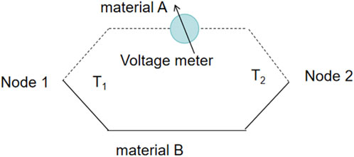
Figure 1. Chematic schematic diagram of thermocouple temperature measurement.
When the absolute thermoelectric potential rates SA and SB of the thin film electrodes A and B are known, and the cold end of the thin film thermocouple is kept at a certain constant and unchanging temperature T0, the specific relationship between the thermoelectric potential rates and the temperature difference can be obtained as shown in Equation 1, which can be seen that: the EAB depends only on the temperature T of the hot end and is not affected by other factors (Tian et al., 2020).
Among them, the hot end temperature is T and the front end temperature is T0. SAB is the Seebeck coefficient.
In order to meet the needs of temperature measurement of automobile engines, a thermocouple is designed in this study, which is mainly composed of the following parts: substrate, insulating layer, NiCr/NiSi thin film electrode and protective layer. The substrate not only bears the thin film layers and wires, but also needs excellent insulation performance to reduce measurement errors caused by thermoelectric potential losses. In this study, three different materials, polyimide, glass and ceramics, were selected as substrates for comparison (Tougas et al., 2013).
Silicon dioxide is used as a protective and insulating layer for thin-film thermocouples because of its high-temperature resistance, excellent insulating properties, strong corrosion resistance, ease of processing, and low cost. NiCr/NiSi thin film electrode has the advantages of high conductivity, high thermal conductivity, high sensitivity to temperature changes, strong corrosion resistance, good chemical stability and low cost, and is considered as an ideal thin film thermocouple electrode material (Liu et al., 2024). The structure of the thin film thermocouple is shown in Figure 2.

Figure 2. Schematic diagram of thermocouple structure.
The ceramic, glass, and polyimide sheets were fabricated in two sizes: 2 × 2 cm and 4 × 4 cm. The thickness of the polyimide sheet was selected as 0.1 mm to optimize flexibility and thermal response, while ceramic and glass substrates were fabricated at 1 mm to ensure mechanical stability and thermal uniformity in high-temperature environments. These substrates are located between the measured material and the transition layer, and their function is to ensure the effective and close connection between the measured material and the thin-film thermocouple. The insulating layers were prepared using an RF magnetron sputtering system (see Figure 3), which employs silicon dioxide (SiO2) as the target material. Key process parameters—including working gas composition (Ar/O), pressure (0.6 Pa), and power density (3.33 W/cm2)—are detailed in Table 1. This method ensures strong adhesion between the film and substrate while enabling uniform large-area coverage.
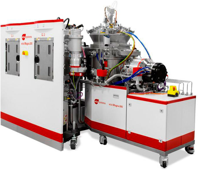
Figure 3. Rf magnetron sputtering.
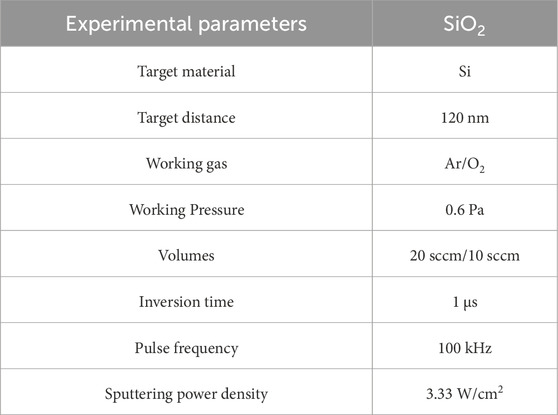
Table 1. Parameters of SiO2 protective film/insulation deposition.
The thickness of the SiO2 insulating layer reaches 1000nm, and the coefficient of thermal expansion is only 0.55 ppm/°C, which is low compared to that of the polyimide sheet (30–35 ppm/°C), alumina ceramic sheet (8–10 ppm/°C), and glass sheet (8–10 ppm/°C), and significantly reduces the risk of damage due to the degree of expansion in the case of a thin-film thermocouple subjected to thermal expansion, which protects the thermocouple layer and thus improves the long-term stability and service life of the product. NiCr/NiSi thin films were deposited by RF magnetron sputtering, in which the mass percentage of NiCr target was Ni: Cr = 90: 10, and the mass percentage of NiSi target was Ni: Si = 97: 3. The NiCr/NiSi films is deposited by using a photomask, and the size of the mask is shown in Figure 4 (when using a 4 × 4 cm substrate, the mask plate was also doubled). The material used for the mask plate is 304 stainless steel with a thickness of 0.2 mm. The physical diagram of the mask plate is as shown in Figure 5. The main technological parameters are shown in Table 2.
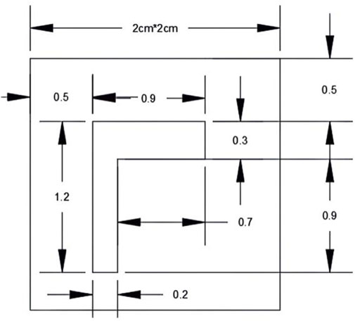
Figure 4. Mask plate dimensions.
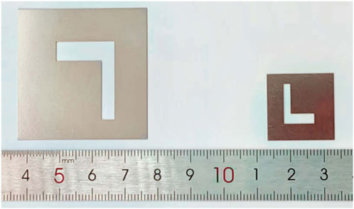
Figure 5. Physical image of the mask plate.
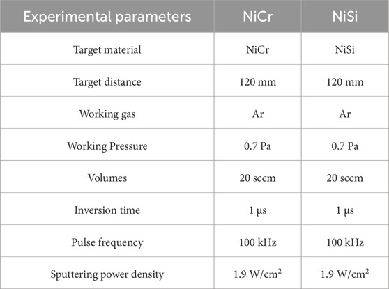
Table 2. Parameters of NiCr/NiSi thin film deposition.
The films were deposited by four sputtering passes (each 20 min apart) at a deposition rate of about 1.28 μm/h, resulting in two NiCr/NiSi thin-film thermocouples with thicknesses of 800 nm and 1,000 nm. The leads connected below the NiCr/NiSi electrodes were NiCrNiSi wires with a diameter of 0.25 mm. The protective layer was prepared by the same RF magnetron sputtering method as the insulating layer, and the process parameters were kept the same, but its thickness was set to 800 nm. The protective layer covers the NiCr/NiSi film, and ensures that the lower lead of the NiCr/NiSi film is exposed, so as to facilitate the connection of the NiCr/Nisi film to the measuring instrument. This design ensures the functionality of the protective layer, and is beneficial to the subsequent wiring operations.
Before the practical application of thin film thermocouples, performing static calibration is a critical step to ensure the accuracy of the measurement results. Static calibration involves acquiring and calibrating the signal of the thin-film thermocouple at a specific temperature to establish an accurate relationship between the thermoelectric potential and temperature (Jiao and Du, 2023). In this study, the comparison method was chosen for calibration. The standard thermocouple and the thin film thermocouple to be tested were placed in the same temperature field for comparison. This method is simple and intuitive, allowing the standard sensor to be different from the sensor to be tested (MA et al., 2014). The experimental program was as follows: The cold end was maintained at room temperature (15°C), while the hot end was immersed in heat-resistant heat-conducting oil inside a beaker. The beaker was heated with an alcohol lamp to raise the temperature of the oil. The electromotive force generated by the thin-film thermocouple was measured using a multimeter. Simultaneously, the temperature change of the heat-conducting oil was monitored with an infrared thermometer, and the corresponding temperature and electromotive force data were recorded as the temperature increased. A schematic diagram of the relevant operating apparatus is shown in Figure 6.
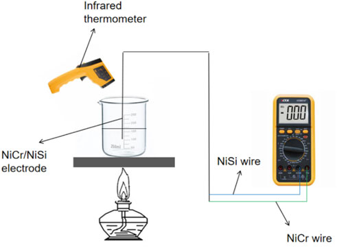
Figure 6. Sketch of the calibration experiment.
Figure 7 shows the calibration curves of the thin-film thermocouple and the standard wire thermocouple. In order to ensure the reliability and accuracy of the experimental results, the thin film thermocouple was repeatedly calibrated. The Seebeck coefficient of the standard wire thermocouple prepared in this article is 0.04020 μV/°C, and the Seebeck coefficient error of the thin film thermocouple prepared in this article is 0.04076 μV/°C, with a difference of only 0.00056 μV/°C. The calibration curve of the thin film thermocouple is basically consistent with the calibration curve of the standard wire thermocouple, indicating that Thin film thermocouples have reached service level.
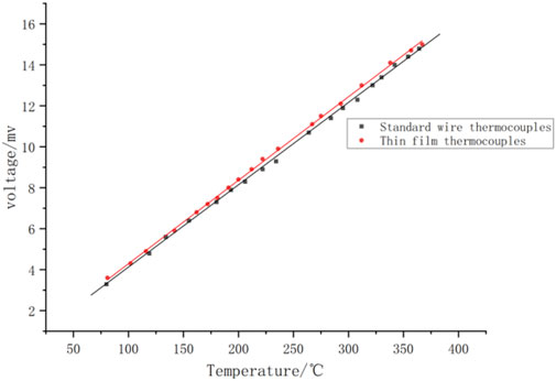
Figure 7. Calibration curves for film thermocouples versus standard wire thermocouples.
Figure 8 shows the results of three experimental fits for thin film thermocouple calibration. The results show that the three fitted straight lines based on the relationship between temperature and electric potential almost completely overlap. The values (0.04076 μV/°C, 0.04075 μV/°C, 0.0414 μV/°C) represent the Seebeck coefficients derived from three independent calibration experiments. For each calibration experiment, multiple temperature-potential data points were collected at 5-minute intervals during both heating and cooling phases. A linear regression fit was then applied to these data points to derive the Seebeck coefficient for each experiment. The arithmetic mean of the three Seebeck coefficients was calculated as:

Figure 8. Repeatability experiment for calibration of thin film thermocouples.
The average absolute difference (0.00043 μV/°C) was computed from the deviations of individual coefficients from the mean:
The final calibration curve (F = 0.04097 T + 0.21518) was derived using the averaged slope and intercept from the three experiments. This approach ensures that the calibration accounts for both systematic (Type B).
Three independent calibration experiments were conducted, each involving 15 temperaturepotential data points collected during heating. The Seebeck coefficients (0.04076 μV/°C, 0.04075 μV/°C, 0.0414 μV/°C) were derived via linear regression for each experiment. The arithmetic mean and dispersion were calculated to establish the final calibration curve, ensuring statistical robustness. Which shows that the response of the thin film thermocouple to temperature changes is very consistent and shows obvious changes. Although there are some errors in the experiment, this is mainly caused by the accuracy limitations of the experimental equipment and uncertain factors in the operation process. By repeating the same calibration experiment, we not only confirmed the repeatability of the experimental results. The thin film thermocouple not only verified the linear relationship between temperature and electromotive force, but also proved its reliability in terms of sensitivity and other properties. Below are linear equations fitted to experimental data for three calibrations.
Where F is the electromotive force at the ends of the film thermocouple in mv. T is the temperature in degrees Celsius. The slope and intercept were averaged separately to obtain a slope of 0.04097 for the calibration image, which is the SAB Seebeck coefficient. The intercept is 0.21518. The relationship between the final temperature and electromotive force is shown below.
The temperature of the car engine is an important parameter for the safe operation of the car. It directly affects the efficiency and safety of the engine. Therefore, it is crucial to check and control the engine temperature. The high-temperature and high-pressure gas generated by combustion drives the piston to reciprocate in the cylinder. A large amount of heat will be generated, and high temperatures will increase mechanical wear, cause component failure, and even cause fires (Adamczak et al., 2009).
Real-time and accurate monitoring of engine temperature ensures proper operation and extends engine life while improving fuel efficiency and safety. Therefore, selecting the appropriate thin film thermocouple material for accurate temperature measurement is critical to ensure the overall safety of vehicle operation. In this study, six thin film thermocouples were precisely fixed at identical positions on the metal surface of the automobile engine. Continuous experiments were conducted, and the high-temperature double-sided tape was applied to secure the thin film thermocouples at the same position on the metal surface of the automobile engine, ensuring their stability throughout the experiments. Substrates include 4 × 4 cm and 2 × 2 cm sheets of polyimide, glass and ceramic. The correct installation of the thin film thermocouple is crucial to the accuracy of the experimental data, so high-temperature resistant polyimide tape is used to achieve close contact and perfect cooperation with the engine, thereby ensuring the accuracy of the measurement. For measurements, 50 cm long NiCr/NiSi wires were connected to both ends of each thin film thermocouple.
This experiment was conducted on a Subaru Outback 2.5i model with engine model FB25B. The experimental process is as follows: First, start the car from a standstill and let the engine start running. Next, the steady refueling operation lasts for 40 min, at which time the power system is cut off. At the same time, we recorded the potential every 5 min. After 40 min, the interval was shortened to 1 min to track the engine’s temperature decay with greater precision. Heating phase (0–40 min): Data points were recorded every 5 min (9 total points). Cooling phase (40–60 min): Data points were recorded every 1 min (21 total points). Post-shutdown, measurements were acquired every 1 min to resolve the cooling dynamics. This resulted in 21 additional data points between 40 and 60 min. The purpose of this is to better draw the potential versus time curve of the car engine. Accurate after refueling and shutting off the engine. Through this curve, we can better analyze the engine temperature indicators. The experimental results are shown in Figure 9. Among them, (a)-(f) are the test results of thin film thermocouples on 2 × 2 cm glass substrate, 2 × 2 cm ceramic substrate, 2 × 2 cm polyimide substrate, 4 × 4 cm glass substrate, 4 × 4 cm ceramic substrate and 4 × 4 cm polyimide substrate.

Figure 9. Voltage-time curves for different substrates. Open circles denote 5-minute intervals (0–40 min); filled circles denote 1-minute intervals (40–60 min): (a) 2 × 2 cm glass substrate; (b) 2 × 2 cm ceramic substrate; (c) 2 × 2 cm polyimide substrate; (d) 4 × 4 cm glass substrate; (e) 4 × 4 cm ceramic substrate; (f) 4 × 4 cm polyimide substrate.
The experimental temperature change process can be divided into three stages: in the first stage, the engine temperature gradually increases, and the heat output of the engine is higher than that of the cooling system and natural heat dissipation; The second stage is the stage when the heat generation and heat dissipation of the engine reach a balance, at which time the engine temperature is unchanged; The third stage is a gradual reduction of the engine temperature, when the engine radiates heat and returns to room temperature. This process fully demonstrates the dynamics of the engine’s heat and heat balance at different time scales.
From Figure 9, we can see that the initial voltage measured by each thermocouple at 0 min is 0.7/0.8mv, which can be calculated from the relationship between temperature and electric potential at 11.8°C–14.3°C. We can see that the electromotive force gradually increases with time in the period of 0–23 min, which reflects that the engine temperature gradually increases with time. During this period, the heat generated by the engine exceeds the ability of the engine cooling system and natural heat dissipation, which led to the continuous increase of temperature and the final voltage rises to 3.1/3.2mv. According to the relationship between temperature and potential, it can be calculated that the voltage is within the range of 70.41°C–72.85°C.
As the engine temperature rises, the rate of warming gradually slows down, and eventually reaches a maximum value and remains relatively stable. This stage marks the equilibrium state between heat generation and heat dissipation of the engine, that is, the heat generation and heat dissipation processes of the engine cancel each other. At the 40 min mark, the car is switched off and the powertrain is switched off, causing the engine temperature to begin to drop gradually. As the decrease of engine temperature, the cooling rate will slow down and finally return to room temperature and remaining stable.
2 × 2 cm Glass: 72.85°C.
2 × 2 cm Ceramic: 70.41°C.
2 × 2 cm Polyimide: 72.85°C.
4 × 4 cm Glass: 70.41°C.
4 × 4 cm Ceramic: 72.85°C.
4 × 4 cm Polyimide: 72.85°C.
Highest Single Measurement: 72.85°C (observed for glass, polyimide, and 4 × 4 cm ceramic substrates).
The highest engine temperature recorded by individual substrates reached 72.85°C (e.g., 2 × 2 cm glass, polyimide, and 4 × 4 cm ceramic substrates). The average of all substrate maxima was approximately 72.03°C, reflecting minor variations in thermal coupling efficiency across materials and sizes. This distinction highlights the importance of substrate selection for precision applications.
Different substrate types have different effects on the measured maximum temperature of the engine. The thermal conductivity of glass is poor, and it is easily affected by temperature as a substrate. Polyimide is expensive, the processing cost is high, and it may corrode some special chemicals, with low thermal conductivity and limited high temperature resistance. Ceramics have better high temperature resistance and thermal conductivity, good dimensional stability, suitable for measurement in high temperature environments, and has good mechanical strength, not easily deformed or damaged, so ceramic materials are the best choice of substrate.
The size of the substrate has an influence on the temperature measurement results of the thin-film thermocouple. Smaller substrates have faster response, shorter heat transfer times, and faster sensing of engine temperature changes. Larger size substrate is relatively more stable, and the larger heat transfer area makes the temperature distribution uniform and reduces the influence of local temperature changes, but the heat transfer time is longer and the response is slower. Considering comprehensively, the small size substrate is more suitable for the scene that needs to monitor the temperature changes quickly, such as measuring the temperature changes of the automobile engine in this experiment. To sum up, in the automobile industry, accurate measurement of engine temperature is very important to ensure vehicle performance and extending engine life. 2 × 2 cm ceramic substrate is adopted because of its excellent thermal conductivity, thermal stability, insulation, mechanical strength and responsiveness. It has become the best choice for measuring the temperature of automobile engines, ensuring that the temperature sensor can still work accurately and stably in high temperature and harsh environment, and providing strong support for performance monitoring and fault prevention of automobile engines.
This study successfully designed and implemented a NiCr/NiSi thinfilm thermocouple for accurate engine temperature measurement. The sensor, fabricated using RF magnetron sputtering, demonstrated a stable Seebeck coefficient of 40.97 μV/°C at 80°C. Calibration trials yielded values of 0.04076 μV/°C, 0.04075 μV/°C, and 0.0414 μV/°C, with an arithmetic mean difference of 0.00043 μV/°C, confirming high repeatability.
Engine tests on a Subaru Outback 2.5i (FB25B engine) revealed a three-phase temperature trend: an initial increase reaching ∼72.03°C, a stable phase, and a gradual cooling phase after shutdown. The measured voltage ranged from 0.7 mV to 3.2 mV, aligning with theoretical expectations. Substrate analysis compared 2 × 2 cm and 4 × 4 cm ceramic, polyimide, and glass substrates. The 2 × 2 cm ceramic-based thermocouple exhibited the best performance due to its high thermal conductivity, stability, and durability, making it the optimal choice for automotive applications.
In conclusion, the NiCr/NiSi thin-film thermocouple provides accurate, reliable, and stable temperature measurements. Its high performance supports real-time engine monitoring, efficiency optimization, and early fault detection, enhancing vehicle performance and safety.
The datasets presented in this study can be found in online repositories. The names of the repository/repositories and accession number(s) can be found in the article/supplementary material.
HW: Writing–original draft, Writing–review and editing.
The author(s) declare that no financial support was received for the research, authorship, and/or publication of this article.
The author declares that the research was conducted in the absence of any commercial or financial relationships that could be construed as a potential conflict of interest.
The authors declare that no Generative AI was used in the creation of this manuscript.
All claims expressed in this article are solely those of the authors and do not necessarily represent those of their affiliated organizations, or those of the publisher, the editors and the reviewers. Any product that may be evaluated in this article, or claim that may be made by its manufacturer, is not guaranteed or endorsed by the publisher.
Adamczak, D., Alesi, H., and Frost, M. (2009). “HIFiRE-1: payload design, manufacture, ground test, and lessons learned,” in 16th AIAA/DLR/DGLR international space planes and hypersonic systems and technologies conference, 7294. doi:10.2514/6.2009-7294
Basti, A., Obikawa, T., and Shinozuka, J. (2007). Tools with built-in thin film thermocouple sensors for monitoring cutting temperature. Int. J. Mach. Tools Manuf. 47 (5), 793–798. doi:10.1016/j.ijmachtools.2006.09.007
Ebner, M., Ziegltrum, A., Lohner, T., Michaelis, K., and Stahl, K. (2020). Measurement of EHL temperature by thin film sensors–Thermal insulation effects. Tribol. Int. 149, 105515. doi:10.1016/j.triboint.2018.12.015
Elanjeitsenni, V. P., Vadivu, K. S., and Prasanth, B. M. (2022). A review on thin films, conducting polymers as sensor devices. Mater. Res. Express 9 (2), 022001. doi:10.1088/2053-1591/ac4aa1
Eom, T. H., and Han, J. I. (2017). The effect of the nickel and chromium concentration ratio on the temperature coefficient of the resistance of a Ni–Cr thin film-based temperature sensor. Sensors Actuators A Phys. 260, 198–205. doi:10.1016/j.sna.2017.04.024
Gierczak, M., Prażmowska-Czajka, J., and Dziedzic, A. (2017). “Design, fabrication and experimental characterization of mixed thick-/thin film thermoelectric microgenerators based on constantan/silver,” in 2017 21st European Microelectronics and Packaging Conference (EMPC) and Exhibition, Warsaw, Poland, 10-13 September 2017 (IEEE), 1–4. doi:10.23919/EMPC.2017.8346900
Jiao, Y. Z., and Du, X. X. (2023). Preparation of CdTe thin films by RF magnetron sputtering. Light Source Light. 2023 (08), 57–59.
Khatri, N., Desai, T., Rai, A., Pratik, K. C., and Moore, A. L. (2018). A batch fabrication-compatible multifunctional thermal sensor based on thin film thermocouple and thermopile elements. Sensors Actuators A Phys. 280, 188–196. doi:10.1016/j.sna.2018.07.038
Kim, S., Lim, S., Jeong, M. H., Kim, W., Baik, S., and Suk, J. W. (2024). Flexible thermocouple using a thermoelectric graphene fiber with a seamless junction. J. Mater. Sci. and Technol. 172, 15–22. doi:10.1016/j.jmst.2023.05.078
Kinnear, K., and Lu, F. (1997). “Design, calibration and testing of transient thin film heat transfer gauges,” in 20th AIAA advanced measurement and ground testing technology conference, 2504. doi:10.2514/6.1998-2504
Lian, Y., Chen, X., Zhang, T., Liu, C., Lin, L., Lin, F., et al. (2023). Temperature measurement performance of thin-film thermocouple cutting tool in turning titanium alloy. Ceram. Int. 49 (2), 2250–2261. doi:10.1016/j.ceramint.2022.09.193
Liu, Z., Tian, B., Liu, J., Zhang, Z., Lin, Q., Mao, Q., et al. (2020). Influences of annealing temperature on the thermoelectric properties of thin film thermocouples based on a flexible substrate by RF magnetron sputtering. Meas. Sci. Technol. 31 (9), 095101. doi:10.1088/1361-6501/ab8c10
Liu, Z., Yang, Y., Sun, Y., Guo, T., Shen, K., Cheng, Y., et al. (2024). Measurement and analysis of surface temperature gradients on magnetron sputtered thin film growth studied using NiCr/NiSi thin film thermocouples. Small 21, 2404829. doi:10.1002/smll.202404829
Ma, X., Yuan, W., and Binghe, M. A. (2014). Preparation and performance study of NiCr/NiSi thin film thermocouple on CFCC-SiC substrate. J. Sens. Technol. 27 (03).
Mutyala, M. S. K., Zhao, J., Li, J., Pan, H., Yuan, C., and Li, X. (2014). In-situ temperature measurement in lithium ion battery by transferable flexible thin film thermocouples. J. Power Sources 260, 43–49. doi:10.1016/j.jpowsour.2014.03.004
Tian, B., Liu, Z., Wang, C., Liu, Y., Zhang, Z., Lin, Q., et al. (2020). Flexible four-point conjugate thin film thermocouples with high reliability and sensitivity. Rev. Sci. Instrum. 91 (4), 045004. doi:10.1063/1.5143044
Tougas, I. M., Amani, M., and Gregory, O. J. (2013). Metallic and ceramic thin film thermocouples for gas turbine engines. Sensors 13 (11), 15324–15347. doi:10.3390/s131115324
Keywords: thin film thermocouple, sensor, automotive engine temperature, magnetron sputtering method, seebeck coefficient
Citation: Wang H (2025) Research on NiCr/NiSi thin film thermocouple sensor for measuring the surface temperature of automobile engine. Front. Mater. 12:1554564. doi: 10.3389/fmats.2025.1554564
Received: 02 January 2025; Accepted: 25 February 2025;
Published: 19 March 2025.
Edited by:
Adriana Greco, University of Naples Federico II, ItalyReviewed by:
Sabrina Gargiulo, University of Naples Federico II, ItalyCopyright © 2025 Wang. This is an open-access article distributed under the terms of the Creative Commons Attribution License (CC BY). The use, distribution or reproduction in other forums is permitted, provided the original author(s) and the copyright owner(s) are credited and that the original publication in this journal is cited, in accordance with accepted academic practice. No use, distribution or reproduction is permitted which does not comply with these terms.
*Correspondence: Haochen Wang, MjI1MTYzNkB0b25namkuZWR1LmNu
Disclaimer: All claims expressed in this article are solely those of the authors and do not necessarily represent those of their affiliated organizations, or those of the publisher, the editors and the reviewers. Any product that may be evaluated in this article or claim that may be made by its manufacturer is not guaranteed or endorsed by the publisher.
Research integrity at Frontiers
Learn more about the work of our research integrity team to safeguard the quality of each article we publish.