 Sheik Mastan
 Anandh Sekar*
- Department of Civil Engineering, SRM Institute of Science and Technology, Kattankulathur, Tamil Nadu, India
Generally, the Openings in composite steel-concrete beams (CBs) for conduits and pipelines often compromise their flexural capacity. To mitigate this, longitudinal stiffeners (LS) and transverse stiffeners (TS) are strategically placed near the web openings. While previous research has explored various opening shapes and stiffener placements, limited studies have examined the impact of stiffener area on flexural performance. This study investigates the influence of stiffener area on the bending performance of composite beams with openings (CBOs). Numerical analysis using ABAQUS (v6.14) was conducted on beams with circular (CBC), rectangular (CBR), and triangular (CBT) openings, varying the breadth of stiffener (b) of LS and TS as 4 mm, 6 mm, 8 mm, and 10 mm. Results indicate that the ultimate load-carrying capacity of CBC with LS and TS increased from 290.50 kN (without stiffeners) to 375.56 kN, 383.46 kN, 387.42 kN, and 400.00 kN as the stiffener breadths were increased to 4 mm, 6 mm, 8 mm, and 10 mm, respectively, finally achieving a 37.6% improvement and comparable to 401.70 kN capacity of a beam without openings (CB). For CBR and CBT with the maximum breath of stiffener, the load-carrying capacities were 37% (380.50 kN) and 73% (336.86 kN) greater, respectively, compared to CBR and CBT without stiffeners. Thus, numerical results indicate that with an increase in the area of both stiffeners, the beam with openings exhibits an ultimate bearing capacity comparable to a beam without web openings. Further experimental investigation was performed on three specimens scaled down at a ratio of 1:0.32; here, the load-bearing capacity of the CBC with both stiffeners of the breath of 10 mm is 156.40 kN, which is 44% greater than the scaled-down CBC of 108.80 kN and comparable to the scaled-down CB’s capacity of 151.12 kN. These experimental and numerical results emphasise that combining LS and TS with the maximum area of stiffeners, i.e., l × b (b = 10 mm), is most effective in maintaining the stability and load capacity of CBOs. Finally, the numerical and experimental results are validated against the theoretical results.
1 Introduction
A composite steel-concrete beam (CB) features a steel I-beam under tension, a concrete slab under compression, and shear connectors, ensuring the two materials are securely joined at their interface (Brozzetti, 2000; Queiroz et al., 2007; Ahmed, 2018; Papastergiou and Lebet, 2014; Shamass and Cashell, 2019; Ashraf et al., 2000; Liu et al., 2017; Peng et al., 2024). Thus, CB effectively maximizes the structural characteristics of steel and concrete. Compared to traditional steel or concrete beams used in isolation, this composite action significantly enhances the beam’s load-carrying capacity, stiffness, and resistance to bending and deflection. By effectively distributing strains and stresses between the concrete and steel components, CB optimizes overall structural efficiency and durability, making it an advantageous solution for applications requiring high strength and minimal deformation in modern construction (Ahmed, 2018; Uy, 2016; Szewczyk and Szumigała, 2021; Ban and Bradford, 2013; Jun et al., 2018; Thomann and Lebet, 2008; Lin et al., 2014; Thevendran et al., 2000; Li et al., 2024). Web openings in composite beams (CBs) allow for integrating services such as electrical conduits and HVAC systems, facilitating greater versatile and efficient building designs. This arrangement can reduce the building’s height and overall cost. However, these web openings can significantly alter stress distribution and load-carrying capacity, potentially affecting the beam’s overall strength and stability (Rex Donahey et al., 1988; Fahmy, 1996; Manuel Benitez et al., 1998; Guo et al., 2023).
Over the past 30 years, various practical and theoretical studies have explored the behavior of CB with web openings (CBO) (Jun et al., 2018; Thomann and Lebet, 2008; Lin et al., 2014; Thevendran et al., 2000; Li et al., 2024; Rex Donahey et al., 1988; Fahmy, 1996; Manuel Benitez et al., 1998; Guo et al., 2023; Ellobody and Young, 2014; Al-Dafafea et al., 2019; DURIF et al., 2021; Mastan et al., 2024; Du et al., 2021; Ellobody and Young, 2016). Balaguru et al. (Tsavdaridis and Galiatsatos, 2015) examined the repercussions of web openings on the structural performance of CBs, using experimental methods to analyze stress distribution and load capacity, and reported a 15%–20% reduction in load-carrying capacity for CBO compared to CB. Garg et al. (Darwin, 1990) conducted a numerical investigation on CBO and found a 12% decrease in overall stiffness and a 30% increase in deflection for beams. Stress concentration factors were found to be 2.5 times higher around the corners of the openings. Ali et al. (Verre, 2022) concluded that CB with larger openings show increased deflection and deformation under applied loads, and common failure modes include shear failure near the openings and localized bending. Martin Classen et al. (Liu et al., 2016) conducted numerical analysis and stated that finite element models closely match experimental results, demonstrating the validity of the modelling approach. David M. Todd et al. (Dassault Systèmes, 2015) stated that composite sections with web openings have significantly higher bending strength than corresponding non-composite sections. Opening length, height, and eccentricity variations significantly affect the ultimate strength.
To enhance CBO load-bearing capacity, Ellobody and Young (2014) conducted a finite element study on CB featuring both reinforced and unreinforced web openings and revealed that CBO reinforced with horizontal stiffeners had a significantly enhanced load-carrying capacity compared to those with unreinforced web openings. Al-Dafafea et al. (2019) Horizontal stiffeners were the most effective, while short stiffeners showed limited benefits and could cause cracks. Monoliteral stiffeners enhanced global stiffness by 12% for high openings and 5% for smaller openings, while double-sided stiffeners improved it by 50%. Both stiffeners significantly enhanced ultimate strength, but strain distribution showed complexities beyond Vierendeel’s theory, indicating the need for further finite element modelling. Evaluation of openings under local loads demonstrated differences in strength and behavior across opening shapes and stiffening methods, suggesting that current design codes may be overly conservative (Durif et al., 2021).
Few studies have investigated the flexural characteristics of CBOs strengthened with stiffeners, as shown in Table 1, as openings can potentially compromise composite beams’ flexural performance and load-bearing capacity (CBs).
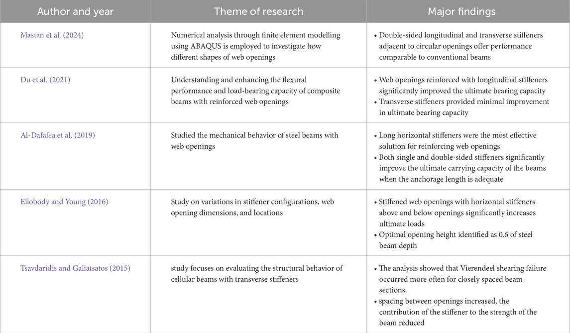
Table 1. Previous studies in CBC with Stiffeners.
Mastan et al. (2024) conducted a study involving twenty-eight numerical models of reinforced web openings analysed under three-point bending. They concluded that CBOs with longitudinal stiffeners (LS) and transverse stiffeners (TS) can achieve a load-bearing capacity comparable to that of CBs. The present study performed numerical analyses with varying shapes of opening and stiffener areas, comparing CB and CB with circular, rectangular and triangular openings. Additionally, experimental tests were conducted on scaled CB, CBO, and an optimized model to predict ultimate bearing capacity.
2 Methodology
Numerical analysis has been carried out on CB, CBO, and CBOs with varying LS and TS areas. The steps involved in numerical analysis are presented in Figure 1. After obtaining the results from the numerical analysis, an experimental investigation was carried out on the optimised model, which was scaled down along with CB and CBC at a ratio of 1:0.32. Scaled-down models’ fabrication and casting were carried out, respectively. Lastly, a numerical, experimental, and theoretical comparison was conducted. This process is illustrated in Figure 1.
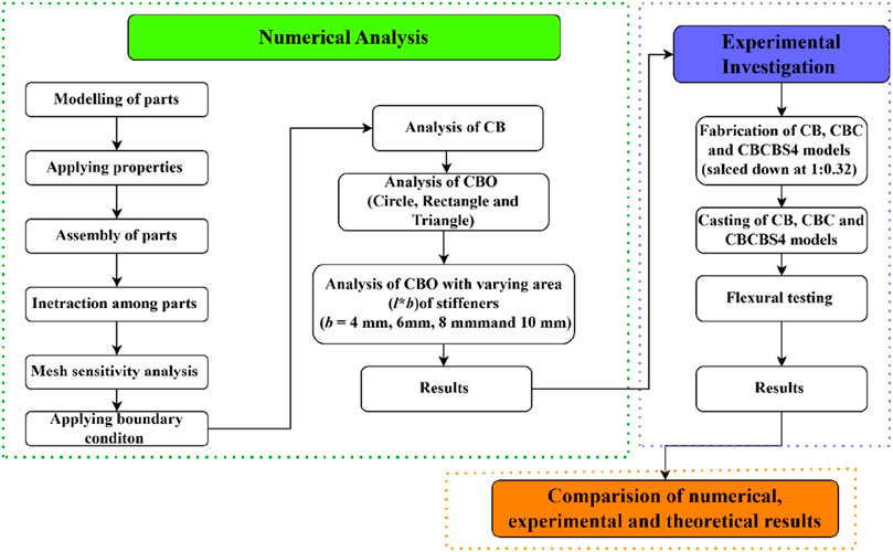
Figure 1. Diagram of methodology.
3 Geometry
The CB is composed of a 4,000 mm-long ISMB 400 steel beam, a one mm-thick deck sheet, shear connectors 90 mm in length and 19 mm in width, and a concrete slab 120 mm thick and 1,200 mm wide. As specified in the AISC Steel Design Guide Series (Darwin, 1990), the stiffener must extend a distance
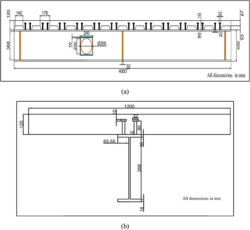
Figure 2. (A) CB Dimensions in mm. (B) Front Elevation in mm.
The geometry of the stiffeners is described in two distinct types: LS and TS. The configurations and placement of these stiffeners adopted from BS EN 1994-1-1 are shown in the accompanying Figure 3, and detailed models are provided in Table 2. LS runs parallel to the beam’s central axis, ensuring alignment along its length. TS are aligned orthogonally to the central axis, providing support across the width of the beam.
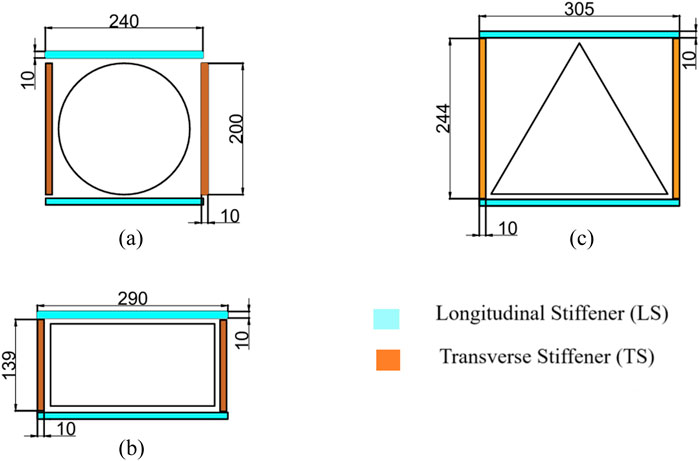
Figure 3. (A) CBCBS4. (B) CBRBS4. (C) CBTBS4.
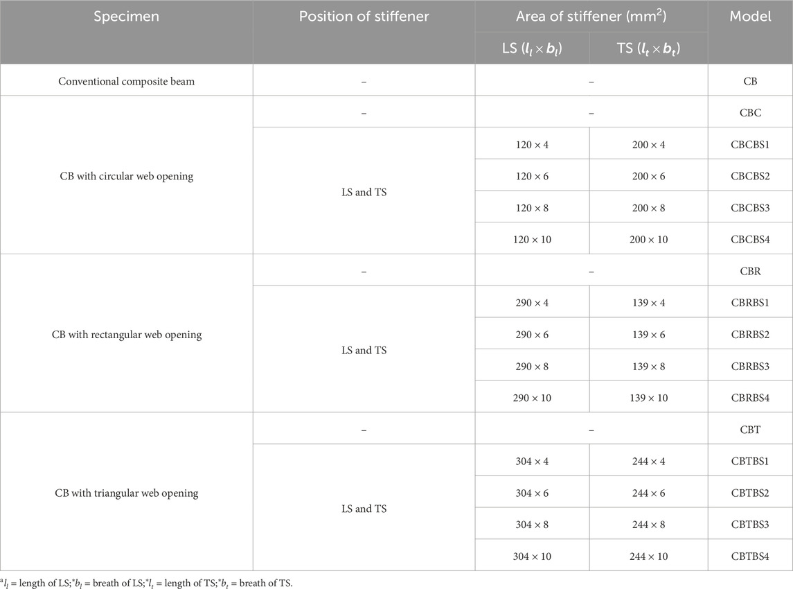
Table 2. Details of the models.
4 Numerical analysis
Finite Element Analysis (FEA) is widely used in civil engineering to model nonlinear behaviours of structures, such as masonry columns strengthened with composites. By incorporating material properties from tensile coupon tests, FEA helps accurately predict structural performance and failure mechanisms under different loading conditions (Verre, 2022).
The maximum capacity of the specimens was evaluated using nonlinear analysis using the dynamic implicit method (Liu et al., 2016). The CB was discretised using solid elements (C3D8R) for the concrete slab, head stud, and steel beam, truss elements (T3D2) for reinforcement, and shell elements (S4) for the deck sheet, respectively (Dassault Systèmes, 2015; Hibbitt et al., 2011; Dong et al., 2021; Numerical et al., 2023; Wang et al., 2019; Han-bing et al., 2010). Based on the material evaluations, Table 3 presents the mechanical attributes of the components in the CB. Tensile coupon evaluations were performed to determine the ultimate tensile and yield strength of all elements except concrete, following ISO 6892–1 guidelines, as shown in Table 3 (Anon ISO 6892-1, 2016). As detailed in Table 4, three cube-shaped compression tests were performed on the concrete for the composite beam sample.
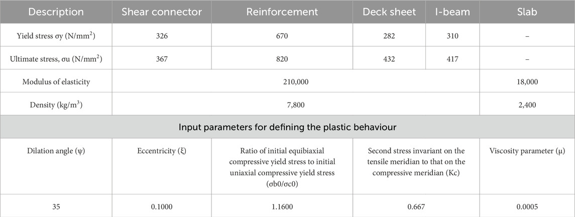
Table 3. Input properties.
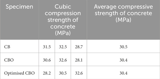
Table 4. Concrete’s physical properties.
Further interaction among components of CB is assigned following Mastan et al. (2023), as depicted in Supplementary Figure S1. Surface-to-surface interaction is adopted between the steel beam and deck sheet, deck sheet and deck slab, shear connectors and steel beam, respectively. Embedded interaction is adopted for shear connectors and reinforcement in the deck slab.
Following a detailed mesh sensitivity analysis, the ideal element sizes for the model were established to optimise accuracy and computing performance. The mesh refinement procedure was performed in multiple critical zones, including the solid area, rib area of the concrete slab, reinforcement, head studs, deck sheet, and steel beam. Reducing the element size enhanced the accuracy of the results, especially in areas with significant stress gradients, such as around web openings and stiffeners. The investigation indicated that further refinement of the mesh above a specific threshold resulted in little enhancements in accuracy while substantially elevating computing expenses. Consequently, the ideal element sizes were chosen for their capacity to ensure consistent convergence while reducing computational expenditure. The final element dimensions were 80 for the solid region, 30 for the rib region in the concrete slab, 100 for reinforcement, 30 for head studs, 20 for the deck sheet, and 40 for the steel beam, as mentioned in Supplementary Figures S2, S3, ensuring the necessary precision and convergence in the model.
For applying the load and boundary condition, the model is supported by end A, which is pinned, and end B, which rests on a roller. A displacement of 10 mm per step is applied at the mid-span of the slab, which is represented by Supplementary Figures S4–S7. The loading and boundary conditions are also depicted in Supplementary Figure S4.
5 Fabrication of Specimen
The CB models were scaled down by a factor of 1:0.32 to maintain geometric similarity and proportion between the model and the prototype, as mentioned in Table 5, ensuring that the mechanical and structural properties of the system were accurately represented. Several key factors were considered when determining this scaling ratio.
• True-to-Scale Proportions: The 1:0.32 ratio was used to emulate the full-scale beam’s section size, concrete slab dimensions, and span within feasible limitations. This scaling ratio guarantees that the scaled model preserves the relative geometry of the components, such as the steel beam, concrete slab, and shear connectors.
• Geometric Compatibility: The dimensions of the concrete slab were proportionately diminished to ensure compatibility between the steel beam and concrete slab in the scaled model. This ensured that both the steel and concrete elements were proportionately scaled, maintaining their interaction under load.
• Market Availability of Materials: Practical factors, including material availability and the feasibility of manufacturing the reduced components, influenced the determination of the scaling factor. The ratio of 1:0.32 rendered the experimental configuration possible within the constraints of commercially obtainable materials for the scaled components.
• Experimental Practicality: The proportions of the scaled model were subsequently optimised according to experimental feasibility, taking into account equipment size restrictions and testing environment constraints. The chosen scaling ratio facilitated the experiment inside the limited space, ensuring that the materials and components were appropriately scaled to align with the testing conditions.
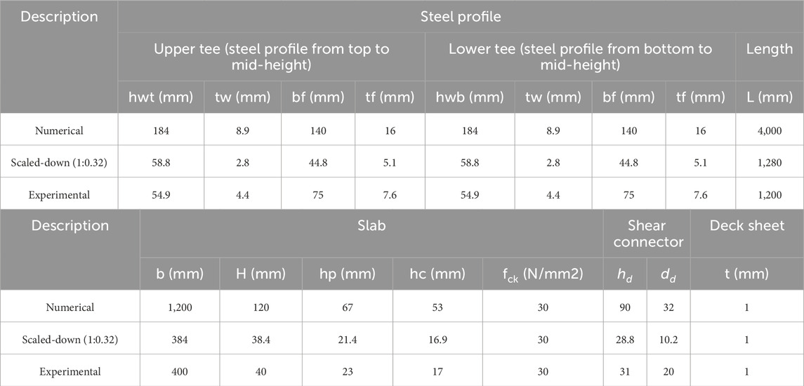
Table 5. Details of scaled-down specimen.
The stud connectors and deck sheet, as detailed in Table 5, are illustrated in Figure 4. The shear connectors are welded onto the steel beam using a stud arc welding machine, also shown in Figure 4. After welding, the reinforcement is attached, and the concrete is cast, as illustrated.
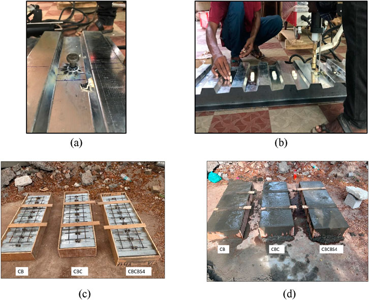
Figure 4. Fabrication of Specimen. (A) shear connector. (B) Arch Stud welding process. (C) Fabrication of CB, CBC and CBCBS4. (D) Casting of CB, CBC and CBCBS4.
6 Experimental test setup
As illustrated in Supplementary Figure S9, the CB samples were subjected to three-point flexural testing using a high-capacity hydraulic actuator of 1,000 kN. To evaluate the effectiveness of the test arrangement, the CB samples were initially exposed to 10% of the estimated peak load applied at 0.5 kN/s and subsequently unloaded. The patterns of cracks and distortions around the opening in the web were monitored and documented after each loading stage. The load was subsequently raised by 5 kN increments until failure was observed. The ultimate load for the standard sample CB was calculated utilising the basic plastic analysis approach described in Eurocode 4 (BSI 2004 BS EN 1994, 2004).
For the CB specimen with web openings, the ultimate load was calculated using the approach outlined by Park et al. (2003) Supplementary Figure S10 and Figures 5, 6 illustrate the positioning of sensors and experimental arrangement for the CB specimens, respectively. LDVTs were deployed at mid-span to monitor the deflections of the CB during testing. The strain around the opening in the web was measured using a 45° strain gauge rosette. Additionally, six strain sensors were installed along the length of the LS to assess the strain pattern along these stiffeners. In contrast, four strain measurement devices were mounted on the TS as shown in Supplementary Figure S10.
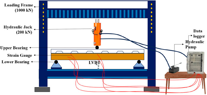
Figure 5. Schematic diagram of Experimental test setup.
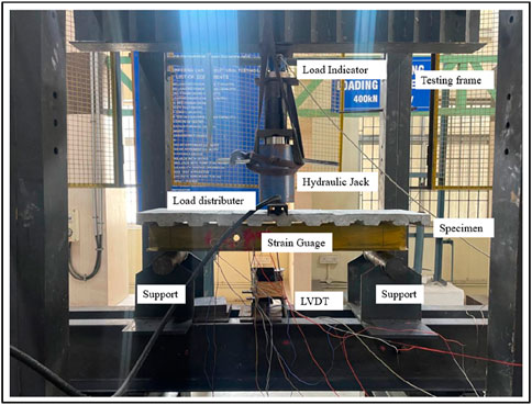
Figure 6. Experimental test setup.
The three-point flexural test was chosen for this study to directly assess the bending response of composite beams under concentrated loading conditions. This test configuration allows for precise evaluation of the beam’s load-carrying capacity, deflection, and failure modes at mid-span, which is critical for understanding the structural behavior of composite beams with web openings and stiffeners. It was selected over alternative testing methods as it provides a clear and focused analysis of bending behavior with well-established data for comparison.
7 Theoretical investigation
From the ASCE (Concrete, 1992) a mathematical model is commonly used to evaluate the load-carrying capacity of CBs with openings on the web. The shear force and bending capacity at the centroid of the web opening were determined by analyzing the cumulative impact of shear force and bending moment. The bending capacity and shear force at the centroid of the web opening were determined by examining the combined effects of the bending moment (Du et al., 2021) and shear force (Du et al., 2021).
Structural analysis allows for calculating the moment shear ratio (γ = M/V) relative to the centroid of the opening once its location is determined.
7.1 Ultimate bending moment at web opening with stiffeners
The axial force of the CB,
The ultimate moment of the beam with the equation is presented in Table 6. The conditions are as follows: the neutral axis is in the slab, top flange, and web of the beam. These conditions of the beam are illustrated in Supplementary Figure S12.
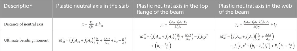
Table 6. Ultimate moment of the beam.
7.2 Maximum shear for CB with stiffener
The web and the accompanying stiffeners mainly sustained the shear loads on the I beams, whereas the contribution of the flange of the I beam in shear was disregarded. The shear capacities of the lower I beam (
With
Shear capacity of lower steel beam.
Correspondingly,
where: Vb = shear capacity of the lower steel beam.
8 Results and discussion
Finite element results, experimental results and theoretical results are compared, and findings are presented in this section.
8.1 Numerical results
Numerical simulation was performed on all beams. The analysis predicted the Vonmises stress, peak principal stresses, fracture patterns, and deformation. Supplementary Figure S13 illustrates the maximum principal stress and deflection for the CB, respectively. In a similar manner, result plots for the other CBs were produced, and the data were compiled in Table 7.
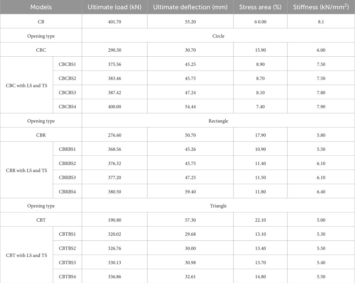
Table 7. FEM results of Models.
Adding reinforcement adjacent to the opening alleviates stress intensification relative to composite beams without such openings. The stress region of each CB was measured and recorded using ImageJ software. Subsequently, the data regarding the ultimate load, ultimate deflection and stiffness of all models are presented in Table 7.
The data in Table 7 indicates that structural capacity is reduced by including an opening. Creating an opening within the CB results in a shift in stress distribution, which increases stress concentrations around the opening’s perimeter, as depicted in Supplementary Figure S14. This concentration decreases the beam’s total load-bearing capacity.
8.1.1 Effect of the area of stiffener on the opening
Among the models considered, the CBCBS4 model demonstrated a higher load-bearing capacity than the other models, as shown in Table 7. CBCBS4 achieved a load-bearing capacity of 400 kN, which is 6%, 4%, and 3% greater than CBCBS1, CBCBS2, and CBCBS3, respectively. Supplementary Figure S15, Figure 7 show the von Mises stress and the load vs. midspan deflection for these models.
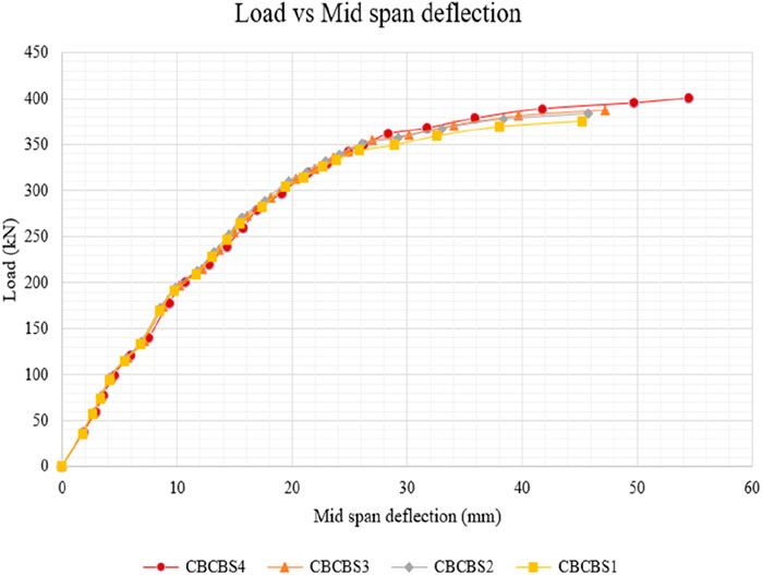
Figure 7. Load vs. Mid-span deflection for CBCBS1 to CBCBS4.
Similarly, the CBRBS4 model reached a load-bearing capacity of 380.50 kN, surpassing CBRBS1, CBRBS2, and CBRBS3 by 3%, 1%, and 1%, respectively. Supplementary File 1 illustrates the load vs. midspan deflection for these models. Finally, the CBTBS4 model also achieved a load-bearing capacity of 336.86 kN, which is 5%, 3%, and 1% higher than CBTBS1, CBRBS2, and CBTBS3, respectively. Supplementary File 2 provides the load vs. midspan deflection for these models. This indicates that an increase in the area of the stiffener increases the load-bearing capacity of CB with web opening. The stiffness for all the models is illustrated in Figure 8, which indicates that openings reduce the stiffness of the models and stiffeners adjacent to openings increase the stiffness. Among the models with opening CBCS4, it attains higher stiffness.
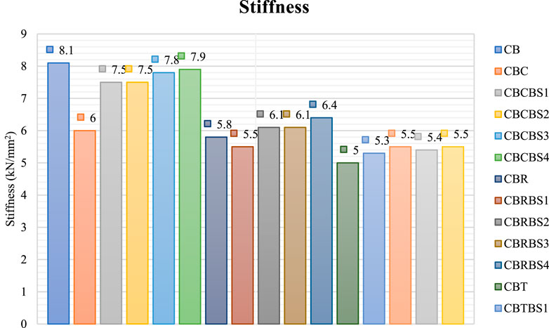
Figure 8. Stiffness of the models.
8.1.2 Effect of shape of opening
The shape of the opening significantly influences the load-bearing capacity of a beam. Supplementary File 3 shows the load versus deflection for CBCBS4, CBRBS4, and CBTBS4. CBCBS4 attained a load-bearing capacity of 400.0 kN, which is 5% and 19% greater than CBRBS4 and CBTBS4, respectively. CBCBS4, CBRBS4, and CBTBS4 stiffness are measured at 7.9 kN/mm2, 6.4 kN/mm2, and 5.5 kN/mm2, respectively. The percentage stress area around CBCBS4, CBRBS4, and CBTBS4 openings is 7.4%, 11.8%, and 14.8%, respectively. In summary, the beam with a circular opening and stiffeners on both sides performs better than beams with rectangular and triangular openings. Load vs. mid-span deflection for these models is illustrated in Figure 9.

Figure 9. Load vs. mid-span deflection for CBCBS4, CBRBS4 and CBTBS4.
8.2 Experimental and theoretical results
The following discussion outlines the experimental results for the scaled-down optimized models CB, CBC, and CBCBS4.
8.2.1 Load deflection behaviour
According to the experimental results, Figure 10 shows the correlations between the applied load and corresponding mid-span deflection in comparison with numerical results. During the initial loading phase, the CBs displayed linear elastic behaviour. As the applied force approached approximately 65% of the maximum load, the central deflection grew swiftly with the increasing stress while the bending rigidity of the CBs gradually reduced. During this phase, the load-displacement graph showed elastic-plastic characteristics. This was primarily due to increased slip between interfaces and the steel beam’s lower flange yield. The empirical results revealed that the CB and CBCBS4 demonstrated a bending bearing capacity of 38% and 36.8% greater than the CBC, respectively. As soon as the section area of the double-sided LS and TS attained the compromised web opening area of the beam, the load-carrying capacity of the CBCBS4 was comparable to CB. The ultimate load-bearing capacity of CB, CBC and CBCBS4 is 151.12 kN, 108.80 kN, and 156.40 kN, respectively.
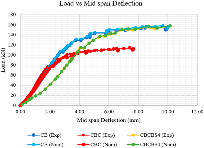
Figure 10. Load vs. mid-span deflection.
8.2.2 Strain behaviour pattern adjacent to the web opening
Figure 11 displays the strain dispersion throughout the vertical dimension of the steel section at the edges of the opening in the web. It was discovered that the steel section’s strain dispersion was segmented and linear. Additionally, the hypothesis that the plane section would remain plane failed to hold here. The strain along the edges surrounding the opening was considerable in CBC, owing to the Vierendeel mechanism. Upon reaching the ultimate load, the shear stresses in the CBC exhibited a sudden increase due to significant shear distortion in the vicinity of the opening in the web. It was discovered that the strain in the region surrounding the opening was reduced due to the reinforcement provided by the stiffeners. The strain profiles of the CBs featuring reinforced web openings showed decreased variability. The primary factor was the effective constraint the stiffeners offered on the opening edges’ distortions. The strain associated with the web opening in CBCBS4 decreased due to the reinforcement provided by the LS and TS. The primary factor was the collaborative interaction between the LS and steel beam. The CBs with stiffened openings can effectively utilize the structural properties of both the LS and TS.

Figure 11. Strain distribution with the height of the steel section. (A) CB. (B) CBC. (C) CBCBS.
Figures 11A–C show the strain distribution along the height of the beam at various load levels (P/Pu). The strain patterns observed in these figures indicate the progressive variation in strain as the load increases. As the load approaches its maximum value (P/Pu = 1), strain near the bottom of the beam increases significantly, suggesting greater engagement of the lower regions in load-bearing. Conversely, the strain near the top remains lower, with the variation depending on the load level.
The strain distribution across the height indicates the beam’s structural behavior under loading. Higher strain concentrations in certain regions, especially near the bottom, suggest areas under higher stress that could lead to potential failure or buckling. As strain variability increases, particularly at higher load levels, the beam’s material properties are progressively engaged, with significant implications for structural stability. These strain patterns help understand the regions of maximum stress and guide the design to prevent overstressing any particular region, ensuring overall stability and optimal load distribution.
8.2.3 Experimental observations and modes of failure
The specimens CB and CBCBS exhibited consistent failure mode and analogous test results. At one-quarter of the ultimate load, horizontal fractures began forming near the centre of the CB. As the load increased to 65% of the maximum, Longitudinal fractures emerged in the middle of the concrete slab at the site of load application, as shown in Figure 12 with numerical counter-plot comparison, accompanied by transverse cracks at the support end. Subsequently, As the imposed load reached approximately 72% of the load-bearing limit, a diagonal fracture emerged in the concrete slab near the opening. It is illustrated in Figure 12, which compares the numerical results. As the load rose to 85% of maximum capacity, the deck sheeting started to marginally separate from the concrete, as shown in Figure 12. Upon reaching the ultimate load, the CBC experienced a failure due to pure shear at the web opening, which was attributed to the occurrence of four plastic hinges. In the case of the samples CB and CBCBS, noticeable gaps were detected between the deck and the concrete at the location of the opening, as shown in Figure 12. The steel web opening showed no visible damage.
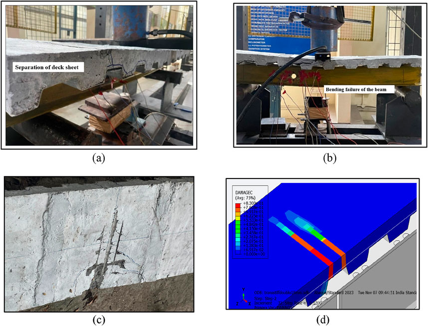
Figure 12. Experimental investigation. (A) separation of deck sheet and concrete slab. (B) Bending failure of the specimen. (C) Cracking pattern in experimental investigation. (D) Cracking pattern in numerical investigation.
The Table 8 presents the critical test results for CB, CBC, and CBCBS. Compared with the numerical results, these experimental findings reveal a significant deviation in the beam’s behaviour under a concentrated load at the midpoint. In this table,
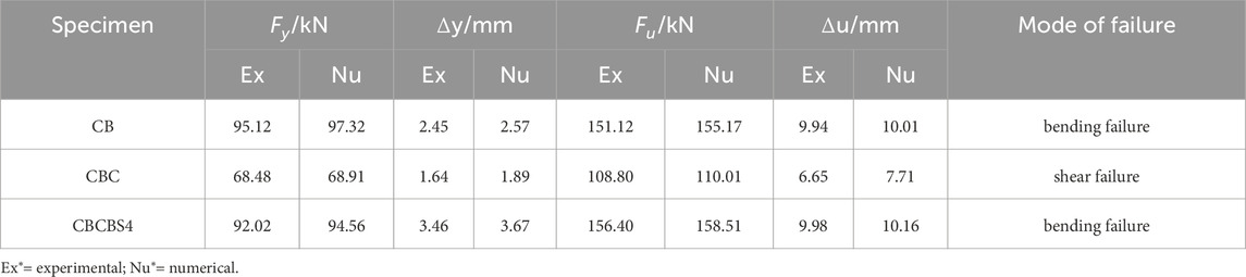
Table 8. Comparison between experimental and numerical results.
The theoretical results are calculated using Equations 1, 2 in the theoretical investigation. The experimental and theoretical results are closely aligned and demonstrate a strong correlation, as shown in Table 9. The ratio of experimental and theoretical results of shear capacity is close to 1.0.

Table 9. Comparison of experimental and theoretical results.
Table 10 summarises the key findings for each model, including ultimate load, ultimate deflection, stiffness, stress area, and mode of failure. It consolidates the results from finite element analysis and experimental calculations, offering a comparative overview of the structural performance of composite beams with web openings and varying stiffener configurations. This summary facilitates the interpretation of the data and highlights the influence of stiffeners and opening shapes on the7 beam’s load-bearing capacity and failure characteristics.
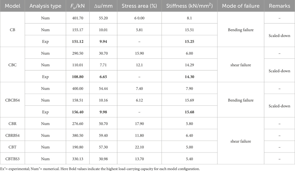
Table 10. Key findings from finite element and experimental.
9 Conclusion
This investigation assessed the effects of the area of stiffeners on the reinforcement of web openings in composite beams. A total of 18 models with various types of stiffeners and web openings were analyzed. The optimized models were scaled down using a 1:0.32 ratio. Three specimens were then designed and subjected to three-point flexural tests. According to the findings, the following conclusions were derived.
• Among the different shapes of openings considered, circular openings attain high load-bearing capacity, high stiffness and low-stress area percentage compared to rectangular and triangular openings.
• Longitudinal and Transverse stiffeners with areas of 1,200 mm2 and 2,800 mm2, respectively, adjacent to the web opening increase the load-bearing capacity of the beam. Thus, CBCBS4 achieved a load-bearing capacity of 400 kN, i.e., 6%, 4% and 3% more than CBCBS1, CBCBS2, and CBCBS3, respectively.
• Similarly, CBRBS4 model reached a load-bearing capacity of 380.50 kN, surpassing CBRBS1, CBRBS2, and CBRBS3 by 3%, 1%, and 1%, respectively. The CBTBS4 model also achieved a load-bearing capacity of 336.86 kN, which is 5%, 3%, and 1% higher than CBTBS1, CBRBS2, and CBTBS3, respectively.
• Primary failure mode was identified in CB and CBCBS4: bending failure. The CBs with stiffeners near web openings showed favourable structural characteristics and enhanced flexibility.
• CBC failed in pure shear failure at the opening, characterised by the development of four plastic hinges and beam bending
• A combination of longitudinal and transverse stiffeners provides greater load-bearing capacity than CBC. CBCBS4 attained a 37% load-bearing capacity compared to CBC. Thus, it proved that CBC reinforced with LS and TS increases the load-bearing capacity of the beam.
Data availability statement
T7he original contributions presented in the study are included in the article/Supplementary Material, further inquiries can be directed to the corresponding author.
Author contributions
SM: Conceptualization, Formal Analysis, Investigation, Methodology, Software, Writing–original draft, Writing–review and editing. AS: Methodology, Supervision, Validation, Writing–review and editing. SS: Conceptualization, Methodology, Validation, Writing–review and editing.
Funding
The author(s) declare that no financial support was received for the research, authorship, and/or publication of this article.
Acknowledgments
The authors would like to acknowledge the Structural Testing Laboratory, Department of Civil Engineering, SRM Institute of Science and Technology, Kattankulathur
Conflict of interest
The authors declare that the research was conducted in the absence of any commercial or financial relationships that could be construed as a potential conflict of interest.
Generative AI statement
The author(s) declare that no Generative AI was used in the creation of this manuscript.
Publisher’s note
All claims expressed in this article are solely those of the authors and do not necessarily represent those of their affiliated organizations, or those of the publisher, the editors and the reviewers. Any product that may be evaluated in this article, or claim that may be made by its manufacturer, is not guaranteed or endorsed by the publisher.
Supplementary material
The Supplementary Material for this article can be found online at: https://www.frontiersin.org/articles/10.3389/fmats.2025.1512695/full#Supplementary-Material
References
Al-Dafafea, T., Durif, S., Bouchaïr, A., and Fournely, E. (2019). Experimental study of beams with stiffened large web openings. J. Constr. Steel Res. 154, 149–160. doi:10.1016/j.jcsr.2018.11.026
Ashraf, A. B., Member, A., and Filippou, F. C. (2000). Mixed formulation of nonlinear steel-concrete composite beam element. J. Struct. Eng. 126, 371–381. doi:10.1061/(asce)0733-9445(2000)126:3(371)
Ban, H., and Bradford, M. A. (2013). Flexural behaviour of composite beams with high strength steel. Eng. Struct. 56, 1130–1141. doi:10.1016/j.engstruct.2013.06.040
Brozzetti, J. (2000). Design development of steel-concrete composite bridges in France. J. Constr. Steel Res. 55, 229–243. doi:10.1016/s0143-974x(99)00087-5
BSI 2004 BS EN 1994 (2004). Structural use of steelwork in building — Part 4: code of practice for design of composite slabs with profiled steel sheeting.
Concrete, T. A. (1992). Commentary on proposed specification for structural steel beams with web openings (with design example). J. Struct. Eng. 118, 3325–3348. doi:10.1061/(asce)0733-9445(1992)118:12(3325)
Darwin, D. (1990). Steel and composite beams with web openings. Steel Design Guide Series AISC-American Institute of Steel Construction.
Dong, S., Guo, J., Zhang, C., An, X., and Lu, M. (2021). Finite element analysis on steel-concrete composite beams considering the bond-slip effect on the interface. IOP Conf. Ser. Earth Environ. Sci. 719, 022030. doi:10.1088/1755-1315/719/2/022030
Du, H., Hu, X., Shi, D., and Fang, B. (2021). Effect of reinforcement on the strength of the web opening in steel-concrete composite beam. Eng. Struct. 235, 112038. doi:10.1016/j.engstruct.2021.112038
Durif, S., Bouchair, A., and AL-Dafafea, T. (2021). Experimental study of various stiffened openings. ce/papers, 4, 1039–1047.
Ellobody, E., and Young, B. (2014). Behaviour and design of composite beams with stiffened and unstiffened web openings. Adv. Struct. Eng. 18, 6–32.
Ellobody, E., and Young, B. (2016). Behaviour and design of composite beams with stiffened and unstiffened web openings. Adv. Struct. Eng. 18, 893–918. doi:10.1260/1369-4332.18.6.893
Fahmy, E. H. (1996). Analysis of composite beams with rectangular web openings. J. Constr. Steel Res. 37, 47–62. doi:10.1016/0143-974x(95)00022-n
Guo, J., Shi, Q., Li, T., and Ma, G. (2023). Mechanical performance of hybrid high-strength steel composite cellular beam under low cyclic loading. J. Constr. Steel Res. 203, 107801. doi:10.1016/j.jcsr.2023.107801
Han-bing, L. I. U., Hui, M. A., Tian-ming, L. I. U., and Yun-long, ZHANG (2010). Analytical solution of steel-concrete composite beam under vertical loads. china J. Highw. Transp. 23, 39–44.
Hibbitt, H., Karlsson, B., and Sorensen, P. (2011). Abaqus analysis users manual. Providence Dassault Systemes Simulia.
Jun, S. C., Lee, C. H., Han, K. H., and Kim, J. W. (2018). Flexural behavior of high-strength steel hybrid composite beams. J. Constr. Steel Res. 149, 269–281. doi:10.1016/j.jcsr.2018.07.020
Li, X., He, J., Zhou, Y., Xu, F., Okazaki, T., and Fang, H. (2024). A comprehensive review of shear connectors in demountable composite beams. J. Constr. Steel Res. 218, 108723. doi:10.1016/j.jcsr.2024.108723
Lin, W., Yoda, T., Taniguchi, N., Kasano, H., and He, J. (2014). Mechanical performance of steel-concrete composite beams subjected to a hogging moment. J. Struct. Eng. 140, 04013031. doi:10.1061/(asce)st.1943-541x.0000800
Liu, X., Bradford, M. A., and Ataei, A. (2017). Flexural performance of innovative sustainable composite steel-concrete beams. Eng. Struct. 130, 282–296. doi:10.1016/j.engstruct.2016.10.009
Liu, X., Bradford, M. A., Chen, Q. J., and Ban, H. (2016). Finite element modelling of steel–concrete composite beams with high-strength friction-grip bolt shear connectors. Finite Elem. Analysis Des. 108, 54–65. doi:10.1016/j.finel.2015.09.004
Manuel Benitez, B. A., Darwin, D., Fellow, Z., and Donahey, R. C. (1998). Deflections of composite beams with web openings. J. Struct. Eng. 124, 1139–1147. doi:10.1061/(asce)0733-9445(1998)124:10(1139)
Mastan, S., Anandh, S., and Sindhu Nachiar, S. (2023). Numerical method and validation using ANN of composite steel–concrete beam for optimized geometry and emplacement of web opening. Asian J. Civ. Eng. 25, 1539–1559. doi:10.1007/s42107-023-00860-6
Mastan, S., Anandh, S., and Sindhu Nachiar, S. (2024). Performance of composite steel-concrete beam with stiffener next to web opening. Eng. Res. Express 6, 035112. doi:10.1088/2631-8695/ad6e56
Numerical, J., Editors, A., Wang, J., Nie, X., Zhao, H., Zhu, Y., et al. (2023). Numerical study on the effect of interface dynamic damage of steel–concrete composite beam bridge caused by high–frequency impact load. Build. (Basel). 13, 545. doi:10.3390/buildings13020545
Papastergiou, D., and Lebet, J. P. (2014). Design and experimental verification of an innovative steel–concrete composite beam. J. Constr. Steel Res. 93, 9–19. doi:10.1016/j.jcsr.2013.10.017
Park, J. W., Kim, C. H., and Yang, S. C. (2003). Ultimate strength of ribbed slab composite beams with web openings. J. Struct. Eng. 129, 810–817. doi:10.1061/(asce)0733-9445(2003)129:6(810)
Peng, F., Xue, W., and Bai, L. (2024). Flexural behavior of externally prestressed continuous steel-concrete composite beams. J. Constr. Steel Res. 212, 108282. doi:10.1016/j.jcsr.2023.108282
Queiroz, F. D., Vellasco, P. C. G. S., and Nethercot, D. A. (2007). Finite element modelling of composite beams with full and partial shear connection. J. Constr. Steel Res. 63, 505–521. doi:10.1016/j.jcsr.2006.06.003
Rex Donahey, B. C., Member, A., and Darwin, D. (1988). Web openings in composite beams with ribbed slabs. J. Struct. Eng. 114, 518–534. doi:10.1061/(asce)0733-9445(1988)114:3(518)
Shamass, R., and Cashell, K. A. (2019). Analysis of stainless steel-concrete composite beams. J. Constr. Steel Res. 152, 132–142. doi:10.1016/j.jcsr.2018.05.032
Szewczyk, P., and Szumigała, M. (2021). Optimal design of steel-concrete composite beams strengthened under load. Materials 14, 4715. doi:10.3390/ma14164715
Thevendran, V., Shanmugam, N. E., Chen, S., and Liew, J. Y. R. (2000). Experimental study on steel-concrete composite beams curved in plan. Eng. Struct. 22, 877–889. doi:10.1016/s0141-0296(99)00046-2
Thomann, M., and Lebet, J. P. (2008). A mechanical model for connections by adherence for steel–concrete composite beams. Eng. Struct. 30, 163–173. doi:10.1016/j.engstruct.2007.03.016
Tsavdaridis, K. D., and Galiatsatos, G. (2015). Assessment of cellular beams with transverse stiffeners and closely spaced web openings. Thin-Walled Struct. 94, 636–650. doi:10.1016/j.tws.2015.05.005
Uy, B. (2016). Applications, behaviour and design of composite steel-concrete structures. Adv. Struct. Eng. 15, 1559–1571. doi:10.1260/1369-4332.15.9.1559
Verre, S. (2022). Numerical strategy for column strengthened with FRCM/SRG system. buildings 12, 2187.
Keywords: composite steel-concrete beam, web opening, area of stiffeners, FEM, load carrying capability
Citation: Mastan S, Sekar A and S. SN (2025) Effects of stiffener area in composite steel-concrete beam with web opening: numerical, experimental and theoretical investigation. Front. Mater. 12:1512695. doi: 10.3389/fmats.2025.1512695
Received: 17 October 2024; Accepted: 16 January 2025;
Published: 27 February 2025.
Edited by:
Annalisa Napoli, University of Salerno, ItalyCopyright © 2025 Mastan, Sekar and S. This is an open-access article distributed under the terms of the Creative Commons Attribution License (CC BY). The use, distribution or reproduction in other forums is permitted, provided the original author(s) and the copyright owner(s) are credited and that the original publication in this journal is cited, in accordance with accepted academic practice. No use, distribution or reproduction is permitted which does not comply with these terms.
*Correspondence: Anandh Sekar, YW5hbmRoc0Bzcm1pc3QuZWR1Lmlu