 Xu Lin
 Limei Zhang
 Yi Xie
- School of Computer and Artificial Intelligence, Beijing Technology and Business University, Beijing, China
DC04 sheet steel is widely used in automotive engineering because of its light weight and high ductility. The sheet steel with holes will emerge stress concentration under loading, then the peripore crack appeared around holes until the fracture occurred. The conventional analysis started around the macroscopic experiment and theoretical analysis, but the study on the evolution law and fracture mechanism of peripore cracks caused by stress concentration effect was not systematic. So, the hole stress of DC04 sheet steel with circular, oval, rectangular and diamond holes were firstly analyzed in this paper. At the same time, 15 groups of tensile tests were verified the influence of cavity shape on stress concentration. Then, taking the sheet steel with circular hole and oval hole as the research object, the evolution of aperture and stress change law were analyzed, and the corresponding empirical formula of stress concentration coefficient about net section was obtained. Finally, the microscopic crack development was observed by electron microscopy, and the crack evolution law and the fracture mechanism caused by stress concentration around the hole were analyzed. These studies will provide theoretical support for the practical engineering design.
1 Introduction
The sheet steel has the characteristics of lightweight, easy opening, convenient assembly and connection, so this steel plates is widely used in the automotive industry (Xu et al., 2021). Around the hole, the stress level increases significantly, so there is stress concentration. The phenomenon of stress concentration is widely observed in automotive engineering (Vivas-Lopez et al., 2021). In practical engineering applications, the severity of stress concentration is typically characterized by the stress concentration factor.
Stress concentration is a classical problem, in 1898, Kirsch (1898) analyzed the stress concentration coefficient of infinite sheet steel with central circular hole under unidirectional tension using two-dimensional elastic theory, and the analytical solution was obtained. Kang (2014) used Airy’s stress function to study the steel plate with any circular hole under the bending moments, and the exact solution of the stress concentration coefficient was obtained. For the stress concentration with non-circular holes, Luo et al. (2012) gained the explicit expressions of the stress concentration factors on elliptical and eccentric oval plates by semi-analytical and semi-empirical methods. Patel and Desai (2020) used the complex function to derive the formula of tangential stress concentration coefficient for a plate with elliptical holes bearing the linearly varying loads. Savin (1961) used Muskhelishvili’s complex variable method to achieve the exact solution of stress distribution with different shapes of holes in infinite plates. Jafari and Ardalani (2016) used the same method to study the stress distribution of regular polygonal holes in finite plates. These analyses showed that the geometric parameters such as the size and shape of the hole have significant influence on the stress concentration.
Subsequent scholarly research has revealed that factors such as plate thickness and material also influence the stress concentration effect in perforated plates. Liu et al. (2024) utilized a theoretical model to analyze the stress state of a finite thickness plate containing a circular hole under remote loading, concluding that when the plate is thin (
The shape and size of the hole, the thickness of the plate, the material properties, and other factors have a significant impact on the stress concentration around the hole. Under load, the area around the hole is prone to damage such as cracking and fracture, making the load an important factor in stress concentration as well. Liu et al. (2023) and others have studied the effect of local plasticity within the notch plastic zone on the actual fatigue stress concentration factor value by using uniaxial tension-compression, bending, and torsional fatigue loading; Goyat et al. (2022) used the extended finite element method to study the influence of edge cracks on the stress concentration around a circular hole surrounded by functionally graded materials under uniaxial tensile load. There is often a close link between macroscopic fracture behavior and the evolution of micro-damage; in-depth research from the micro perspective can more specifically reveal the fracture mechanism of the hole plate under the effect of stress concentration. Habibi et al. (2022) compared and analyzed the microstructural damage behavior of sheet steel (thickness of 1.5 mm) under different stress states, revealing the complex relationship between microstructure and damage evolution; the uniformity of microstructure is closely related to the local formability and fracture behavior of the material. Sun et al. (2023) combined numerical simulation and theoretical analysis to discuss and analyze the state of Q345 steel plate (thickness of 5.5 mm) during impact; the results showed that the steel plate exhibited obvious damage and destruction characteristics macroscopically, and microscopically, the holes were mainly distributed near the edge of the ferrite grains, where micro-cracks nucleated and expanded into macroscopic cracks. Tan et al. (2023) have conducted in-situ tensile tests to study the stainless steels SLM316L and CM 316L, and it has been observed that the former exhibits greater strength and resistance to deformation. The stress concentration at the crack tip significantly influences the strain-induced α′-martensitic transformation. The aforementioned studies indicate that stress concentration is the main cause of micro-pores and crack formation around the hole, and the size and propagation path of the cracks will, in turn, affect the stress distribution and cyclic state around the hole. Under this complex interaction, the two will eventually lead to the fracture and destruction of the component.
In summary, the present study centers on DC04 sheet steel for investigation. The distribution of stress and strain around holes of circular, elliptical, rectangular, and diamond shapes is initially analyzed. Subsequently, the influence of hole geometry on stress concentration effects is verified by conducting 15 sets of tensile tests. Empirical formulas for the net section stress concentration factors in sheet steel featuring circular and elliptical holes are then derived through an analysis of the relationship between hole diameter evolution and stress concentration. Finally, the fracture morphology of the specimens is examined using scanning electron microscopy to investigate the progression of cracks around the holes and the fracture mechanisms of sheet steel induced by stress concentration. The study aims to systematically delineate the impact of stress concentration on materials by integrating numerical simulation with experimental methods, thus offering a theoretical foundation for research in pertinent domains.
2 Stress concentration characteristics of thin steel plates with different holes
The stress concentration factor (SCF) is expressed as follows (Lim, 2015):
where
where
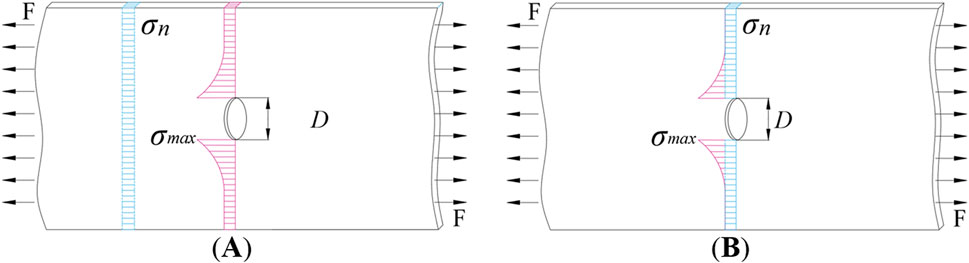
Figure 1. Two types of
According to the principle of equivalent area, four types of specimens were designed Figure 2, four kinds of hole shapes were circular oval, rectangular and diamond. The sheet steel, designated as DC04, with a thickness of 1 mm.
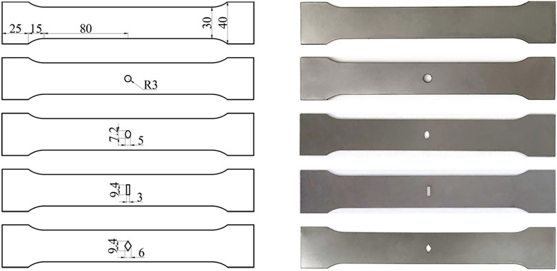
Figure 2. The Geometry size of four types hole plate.
The material parameters of DC04 sheet steel: yield strength of 120 MPa; tensile strength of 270 MPa; modulus of elasticity of 205000 MPa; density of 7850 kg/m3; Poisson’s ratio of 0.3. In the context of uniaxial tensile loading, the mechanical behavior of the sheet steel with four types of holes was investigated both numerical simulation and experimental, with the results as follows.
2.1 Numerical simulation
In ABAQUS, the C3D20R element was selected, and the mesh around the hole was locally refined. Under uniaxial tensile conditions, the left end of the sheet steel was fixed, and a uniform load of 200N was applied to the right end (Figure 3 illustrates the example of plate with a circular hole). The stress-strain conditions around the hole, as calculated, were depicted in Figure 4, and the mechanical properties were presented in Table 1.
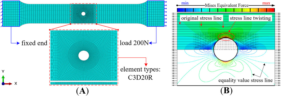
Figure 3. Circular hole plate (A) boundary conditions (B) stress line distribution.
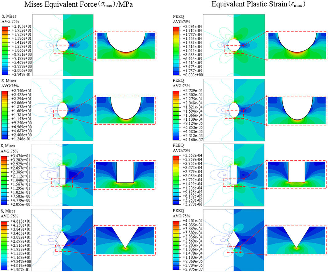
Figure 4. The stress and strain distribution around four types of holes.
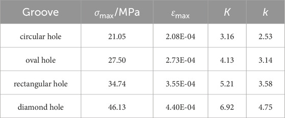
Table 1. Mechanical parameters around the hole.
From Figures 3, 4; Table 1, the results were shown as: 1) The distribution of stress and strain around the hole periphery was expressed a typical “butterfly shape” and stress concentration. The geometric discontinuity caused by the hole opening led to the distortion of stress lines around the hole. The denser the strain lines around the hole, the more pronounced the stress concentration was observed to be. 2) The stress concentration around the diamond-shaped hole was the most pronounced, with the maximum equivalent stress value reaching 46.13 MPa; the stress concentration around the circular hole plate was the lowest, with the maximum equivalent stress value being 21.05 MPa. The shape of the hole directly influenced the distribution of stress.
2.2 Sheet steel tensile test
In accordance with the relevant provisions of the Chinese National Standard GB/T228.1-2010 (Li et al., 2024), specimen preparation and tensile testing were conducted. Tensile tests were conducted using an electronic universal testing machine, with a maximum static load of 300 kN and a loading rate of 2 mm/min. Each type of specimen was tested three times, grouped and numbered as TS1, TS2, and TS3. The load-displacement curves for the unperforated and four perforated specimens are shown in Figures 5, 6, respectively.
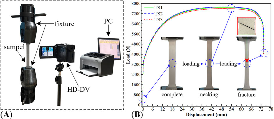
Figure 5. Tensile test of unperforated specimens (A) test equipment (B) load-displacement curve and macro damage evolution.
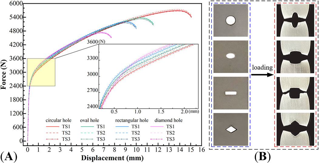
Figure 6. Tensile test of perforated specimens (A) load-displacement curve (B) fracture topography.
The experimental results indicated that: Macroscopically, 1) DC04 unperforated specimens exhibited significant plastic deformation when subjected to load, without immediate fracture. After the specimen fractured, the fracture angle was approximately 60°, which differed from the theoretical value of 45°. The reasons for this discrepancy included the specimen’s good toughness, its thinness, susceptibility to warping deformation during the manufacturing process, and the influence of material elemental characteristics on the stress state at the fracture. 2) Post-yield, the force-displacement curves and the morphologies of the holes began to exhibit noticeable differences. Rectangular and diamond-shaped holes were the first to crack, with significant stress concentration at the two sharp corners perpendicular to the stretching direction, leading to rapid fracture after reaching the maximum tensile stress. In contrast, the stress concentration around circular and oval holes was less pronounced, with smaller cracks around the holes and better ductility.
In summary, numerical simulations and experimental results had demonstrated that the shape of holes significantly influenced stress concentration and crack propagation. Holes with smooth boundaries and gradual geometric transitions, such as circular and oval holes, exhibited less stress concentration and smaller cracks around them, resulting in better ductility. Consequently, the study primarily focused on the stress concentration issues of plates with circular and oval holes in the subsequent research.
3 Stress concentration of the sheet steel with circular and oval hole
3.1 Circular hole plate
A model of the sheet steel with a central circular hole was shown in Figure 7. Its length width and thickness were expressed as
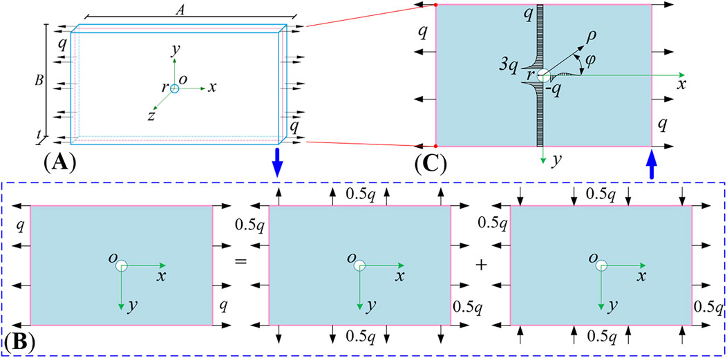
Figure 7. The model of sheet steel with central circular hole (A) 3D modelling of the orifice plate (B) flat model (C) superposition principle.
The circumferential normal stress component surrounding the hole was derived using the superposition method, as reported in (Xu, 2013):
where the polar coordinate system,
When
When
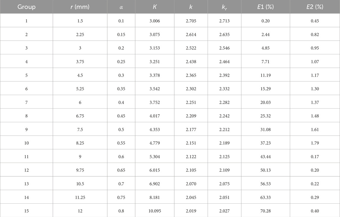
Table 2. SCF around the hole corresponding to different
The numerical solution
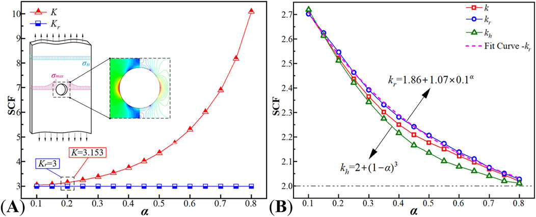
Figure 8. Correspondence of
These results indicated that: As shown in Figure 8A, when
In the relationship curve of Figure 8B,
The formula was compared with the computational results of Hey Wood (Frankl, 1953) (referred to as
3.2 Oval hole plate
The same mechanical model of the sheet steel as in Figure 9A was used and the mechanical model was simplified to a planar problem for analysis (Figure 9B). The hole at the center of the thin plate was designed as an oval hole (with the major axis as
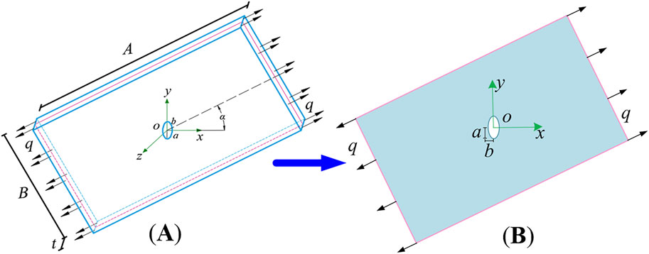
Figure 9. The model of sheet steel with central oval hole (A) 3D modelling of the orifice plate (B) flat model.
By referring to the work cited as (Tan, 2015), the problem was addressed using methods from complex function theory, resulting in the formulation of
where
When
When

Table 3. SCF around the hole corresponding to different
The numerical solution
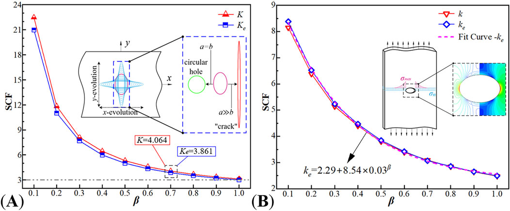
Figure 10. Correspondence of
Research indicated that
In Figure 10B, a negative correlation was observed between
By maintaining the constant area of the perforation in sheet steel and analyzing the stress concentration around the hole with the evolution of the oval hole aperture, the study of stress concentration in finite large plates containing oval holes had been refined to a certain extent. Equation 4 employed a unique variable to precisely quantify the degree of stress concentration around the hole, with succinctly characterizing the two extreme scenarios of oval hole diameter evolution. This approach enhanced efficiency in structural design and engineering calculations.
4 Micro-crack development and fracture mechanism around the hole
The fracture morphology of the non-hole sheet steel and four other types of porous plates was observed using a Scanning Electron Microscope (SEM), with the observation direction and the position of the observation points as depicted in Figure 11.
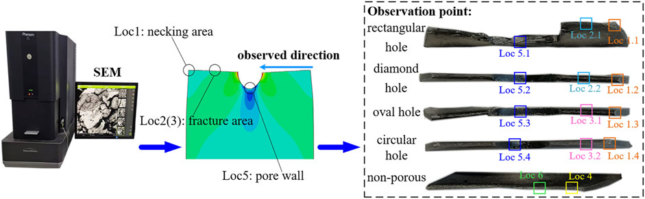
Figure 11. Observation direction and observation point.
The fracture surface of the specimen was observed via SEM to exhibit a substantial presence of slip bands and a dimple zone formed by the aggregation of dimples, as illustrated in Figure 12.
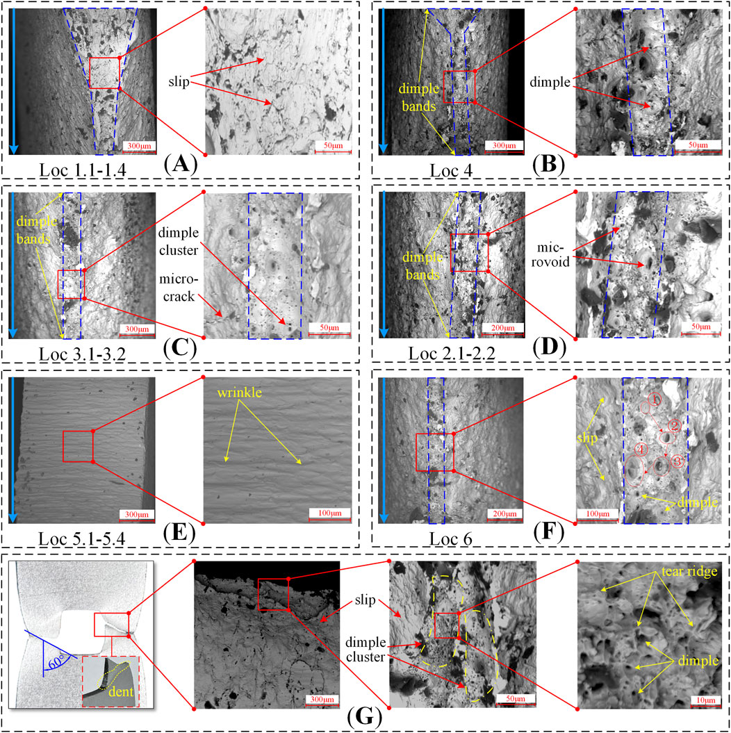
Figure 12. Micro-morphology (A) slip direction of necking area (B) dimples of fracture area (C) dimples of circular and oval orifice plates (D) dimples of rectangular and diamond orifice plates (E) pore wall (F) microscopic damage evolution of peripore (G) rectangular hole damage.
The results were shown that:
(1) The transition zone at the fracture surface exhibited a pronounced necking phenomenon, with the slip direction towards the side closer to the hole (Figure 12A). The near-hole region was the first to develop microcracks, which gradually propagated towards both ends until reaching the surface of the specimen. In this area, dimples coalesced and formed a dimple zone, which then progressively developed into a crack, extending from the central region towards both ends (Figure 12B). The dimples on the fracture surface were distributed with a pattern of increasing density and decreasing size as the distance from the hole mouth increased; the cracks on the hole plate initiated in the central region and gradually expanded towards both ends.
(2) In the context of fracture surfaces, circular and oval holes exhibit a lower density of dimples (Figure 12C), whereas rectangular and diamond-shaped holes display a higher density of dimples (Figure 12D). This phenomenon can be attributed to the presence of second-phase particles and other impurities within the material, which lead to the formation of micro-pores and micro-cracks. The geometric continuity of rectangular and diamond-shaped holes is relatively poor, resulting in a significantly increased crack propagation rate at the sharp corners, which rapidly expands along the damage path. The corners with holes are prone to early fracture. In contrast, the smooth boundaries of circular and oval holes result in weaker stress concentration around the hole, thus the initiation and propagation of micro-cracks are relatively slow. This effect delays the fracture process of the plate to some extent, and as a result, circular and oval hole plates demonstrate higher tensile strength.
(3) Observations of the inner wall of the hole at the fracture revealed that: it was observed that the inner walls of the holes exhibited minor undulation deformation, as illustrated in Figure 12E at Loc 5.1–5.4 (illustrates the example of plate with a circular hole). This phenomenon indicates that the stress perturbation experienced in this area was relatively minor, which is also in accordance with the stress distribution patterns around the holes as simulated numerically.
(4) The maximum stress concentration observed in Figure 4 occurred in the region of the sharp corners of the rectangular hole, and Figure 6 showed that the peripheral cracks of the hole exhibited asymmetry, with the locations of sprouting located in the left and right side regions. According to Figure 12G, the reason for this phenomenon was twofold: firstly, the necking of the inner wall of the hole in the thickness direction, where the thickness of both sides was smaller compared to that at the sharp corners, and the former was more susceptible to fracture; and secondly, there were a large number of clusters of tough foci, slip lines, and microcracks in the walls of the holes on the left and right sides. The convergence of these tough nests, the slip of grains, and the presence of twin boundaries provided potential sites for crack initiation, and the distinctness of the tearing prongs suggested a higher rate of damage evolution in this region. Inclusions in the material could lead to crack initiation at defects at lower stress levels, the specimens were thin and prone to buckling, and the fracture exhibited shear damage (fracture angle of approximately 60°), all of which may have had an impact on the crack extension path.
The hole edge was a potential area for the initiation and propagation of cracks, with the first macroscopic crack typically originating from both ends of the hole and gradually expanding towards the ends in a direction orthogonal to the loading. Microscopically, the growth of dimples and the aggregation of slip were common forms of damage accumulation, where the growth of dimples represented the micro-injury evolution of material toughness fracture, as shown in Figure 12[F(①–④)]. These micro-features had a direct link to the macro-behavior of the material and could systematically elucidate the fracture mechanism of the sheet steel.
5 Conclusion
This study employed a combination of numerical simulation and experimental methods to investigate the behavior of DC04 sheet steel under uniaxial tensile loading conditions. The research materials included plates with different hole patterns, circular hole plates with various hole diameters, and elliptical hole plates with the same area but different hole diameters. The findings of the study led to the following conclusions:
(1) The shape of the hole has a significant impact on stress concentration. Holes with sharp corners are prone to higher degrees of stress concentration around the hole, while holes with smooth edges significantly mitigate stress concentration. The edges of the holes in the sheet steel are potential areas for crack initiation and propagation, and the first macroscopic crack in all hole plates originated at both ends of the hole, developing in a direction perpendicular to the loading.
(2) By defining the aspect ratio
(3) The fracture analysis of plates with holes under the effect of stress concentration indicated that the area of the plate with the smallest cross-section (near the hole) exhibited significant stress concentration first. As the stress concentration further intensified, plastic yielding occurred on a macroscopic level; on a microscopic level, the movement of dislocations within the material generated local micro stress concentrations, which in turn led to the formation of micro holes or depressions in the material, known as dimples.
(4) The intensification of dislocation motion caused plastic deformation to initiate in regions such as grain boundaries and phase interfaces within the material, accelerating the growth of dimples and forming a continuous dimple zone. When the volume of dimples grew to a critical state, adjacent large-volume dimples came into contact and coalesced, a process that was observed macroscopically as a noticeable necking phenomenon around the hole. As the dimples accelerated their convergence, micro cracks in the hole area continued to propagate, and when the stress concentration around the hole reached the ultimate value that the plate could withstand, the sheet steel began to crack at the hole mouth and eventually fractured completely.
Data availability statement
The original contributions presented in the study are included in the article/supplementary material, further inquiries can be directed to the corresponding author.
Author contributions
XL: Conceptualization, Data curation, Formal Analysis, Investigation, Methodology, Visualization, Writing–original draft. LZ: Funding acquisition, Project administration, Resources, Supervision, Writing–review and editing. YX: Writing–review and editing.
Funding
The author(s) declare that financial support was received for the research, authorship, and/or publication of this article. This study was funded by the National Natural Science Foundation of China (Grant No. 52078005).
Conflict of interest
The authors declare that the research was conducted in the absence of any commercial or financial relationships that could be construed as a potential conflict of interest.
Publisher’s note
All claims expressed in this article are solely those of the authors and do not necessarily represent those of their affiliated organizations, or those of the publisher, the editors and the reviewers. Any product that may be evaluated in this article, or claim that may be made by its manufacturer, is not guaranteed or endorsed by the publisher.
References
Chai, K. F., Woon, K. S., Wong, J. K., Lim, J. H., Lee, F. W., and Lee, Y. L. (2023). Experimental and numerical study of the strength performance of deep beams with perforated thin mild steel plates as shear reinforcement. Appl. Sci. 13, 8217. doi:10.3390/app13148217
Dveirin, O. Z., Andreev, O. V., Kondrat’ev, А. V., and Haidachuk, V. Y. (2021). Stressed state in the vicinity of a hole in mechanical joint of composite parts. Int. Appl. Mech. 57, 234–247. doi:10.1007/s10778-021-01076-4
Frankl, E. K. (1953). Designing by photoelasticity. R. B. Heywood. Chapman and Hall, London 1952. 414 pp. 65s. Net, J. R. Aeronaut. Soc. 57, 472–473. doi:10.1017/S000192400012202X
Goyat, V., Verma, S., and Garg, R. K. (2022). Effect of an edge crack on stress concentration around hole surrounded by functionally graded material layer. Eng. Solid Mech. 10, 325–340. doi:10.5267/j.esm.2022.6.005
Habibi, N., Mathi, S., Beier, T., Könemann, M., and Münstermann, S. (2022). Effects of microstructural properties on damage evolution and edge crack sensitivity of DP1000 steels. Crystals 12, 845. doi:10.3390/cryst12060845
Jafari, M., and Ardalani, E. (2016). Stress concentration in finite metallic plates with regular holes. Int. J. Mech. Sci. 106, 220–230. doi:10.1016/j.ijmecsci.2015.12.022
Kang, J.-H. (2014). Exact solutions for stresses, strains, and displacements of a rectangular plate with an arbitrarily located circular hole subjected to in-plane bending moment. Int. J. Mech. Sci. 89, 482–486. doi:10.1016/j.ijmecsci.2014.10.019
Kirsch, E. G. (1898). Die Theorie der Elastizit t und die Bed rfnisse der Festigkeitslehre. Zeitshrift Des. Vereines Dtsch. Ingenieure 42, 797–807.
Li, D., Cheng, B., Xiang, S., and Zhou, H. (2024). Integrative measurement method for tensile test based on DIC using modified second-order shape function. Measurement 226, 114098. doi:10.1016/j.measurement.2023.114098
Lim, T.-C. (2015). “Stress concentration, fracture and damage in auxetic materials,” in Auxetic materials and structures. Editor T.-C. Lim (Singapore: Springer), 147–169. doi:10.1007/978-981-287-275-3_4
Liu, H., Deng, L., and Wang, W. (2024). 3D stress concentration around circular hole under remote biaxial loading. Int. J. Mech. Sci. 268, 109032. doi:10.1016/j.ijmecsci.2024.109032
Liu, M., Oliveira Miranda, A. C. D., Avelar Antunes, M., Meggiolaro, M. A., and Pinho De Castro, J. T. (2023). Plastic stress concentration effects in fatigue strength. Int. J. Fatigue 168, 107394. doi:10.1016/j.ijfatigue.2022.107394
Luo, L., Xiang, Y., and Wang, Q. (2012). Stress concentration factor expression for tension strip with eccentric elliptical hole. Appl. Math. Mech. Engl. Ed. 33, 117–128. doi:10.1007/s10483-012-1537-7
Patel, A., and Desai, C. K. (2020). Stress concentration around an elliptical hole in a large rectangular plate subjected to linearly varying in-plane loading on two opposite edges. Theor. Appl. Fract. Mech. 106, 102432. doi:10.1016/j.tafmec.2019.102432
Savin, G. N. (1961). Stress concentration around holes. Pergamon Press. Available at: https://cir.nii.ac.jp/crid/1572261549002108544.
Sun, H., Ma, Y., Cai, Q., Zhou, G., Duan, Y., and Zhang, M. (2023). Study on the effect of impact on the macro- and micro-structure of Q345 steel plate. J. Mater. Eng. Perform. 33, 9321–9335. doi:10.1007/s11665-023-08630-w
Tadepalli, G., Gayatri Vineela, M., and Janardhan Reddy, T. A. (2017). Analysis of stress concentration in isotropic and orthotropic plates with hole under uniformly distributed loading conditions. Mater. Today Proc. 4, 740–745. doi:10.1016/j.matpr.2017.01.080
Tan, L. (2015). Study on scale effect of hole-edge stress concentration in thin plate. Master’s thesis. Chongqing (China): Chongqing University.
Tan, Z., Gui, M., Zhou, Z., Lv, J., Zhang, S., and Wang, Z. (2023). Crack propagation and strain-induced α'-martensite transformation in selective laser melting 316L stainless steels. Front. Mater. 10, 1264709. doi:10.3389/fmats.2023.1264709
Vivas-Lopez, C. A., Tudon-Martinez, J. C., Estrada-Vela, A., De Jesus Lozoya-Santos, J., and Morales-Menendez, R. (2021). Damping variation effects in vehicle semi-active mr suspensions: a stress concentration analysis. Front. Mater. 8, 590390. doi:10.3389/fmats.2021.590390
Xu, J., Sheng, H., Zhang, S., Tan, J., and Deng, J. (2021). Surface accuracy optimization of mechanical parts with multiple circular holes for additive manufacturing based on triangular fuzzy number. Res. Article 16, 133–150. doi:10.1007/s11465-020-0610-6
Keywords: sheet steel, hole, stress concentration, crack evolution, fracture mechanism
Citation: Lin X, Zhang L and Xie Y (2025) Research on the stress concentration effects and fracture mechanisms of DC04 sheet steel with holes. Front. Mater. 12:1488624. doi: 10.3389/fmats.2025.1488624
Received: 30 August 2024; Accepted: 09 January 2025;
Published: 29 January 2025.
Edited by:
Nicola Maria Pugno, University of Trento, ItalyCopyright © 2025 Lin, Zhang and Xie. This is an open-access article distributed under the terms of the Creative Commons Attribution License (CC BY). The use, distribution or reproduction in other forums is permitted, provided the original author(s) and the copyright owner(s) are credited and that the original publication in this journal is cited, in accordance with accepted academic practice. No use, distribution or reproduction is permitted which does not comply with these terms.
*Correspondence: Limei Zhang, emhhbmdsaW1laUBidGJ1LmVkdS5jbg==