 Jun Zhou1,2
 Yongqiang Zhang1,2,3
 Feng Qin1,2Xuelong Zhang1,2Hao Wang1,2Ze Liu1,2Wenhan Zhang1,2Caiyan Huang1,2Chunbo Zhang1,2*
- 1Harbin Welding Institute Limited Company, China Academy of Machinery, Harbin, China
- 2Heilongjiang Key Laboratory of Advanced Friction Welding Technology and Equipment, Harbin, China
- 3AECC Commercial Aircraft Engine Co., Ltd., Shanghai, China
Nickel-based superalloys are indispensable in aerospace engines due to their exceptional high-temperature strength, oxidation resistance, and corrosion resistance, making them critical for joining processes such as inertia friction welding (IFW), which is favored for its efficiency and superior joint quality. In this study, IFW was used to join FGH101 powder superalloy with IN718 deformed superalloy, resulting in significant plastic deformation that formed symmetrical ear-shaped flash on the IN718 side and minor upsetting on the FGH101 side, with a wavy interface due to heat dissipation. Microhardness analysis revealed higher hardness at the weld interface, followed by a sharp decline near the Heat Affected Zone (HAZ) on the IN718 side due to phase re-dissolution, while FGH101 showed quicker recovery. Post-weld aging treatments enhanced hardness and strength through γ′ and δ phase precipitation in FGH101 and γ″ phases in IN718. Room temperature tensile tests demonstrated impressive strength with failures occurring plastically within the IN718 base metal, whereas elevated temperatures shifted failure locations to the weld zone without necking. Fatigue tests exhibited varied lifespans, with fractures initiating either at stress concentrators or within the FGH101 base metal far from the weld center. Scanning electron microscope (SEM) analysis confirmed mixed-mode fracture patterns, underscoring the importance of microstructure on joint performance and suggesting that optimizing IFW parameters can lead to superior weld quality in aerospace components, thus providing valuable insights for future research and industrial applications.
1 Introduction
Nickel-based superalloys, renowned for their high-temperature strength, oxidation resistance, and corrosion resistance, play a critical role in the manufacture of aerospace engines. They are extensively utilised in the hot sections of engines, such as compressor blades and turbine disks, which are subjected to extreme conditions of high temperatures, pressures, and rotational loads. As an efficient and energy-saving welding technology, friction welding has seen rapid development in recent years (Mahaffey et al., 2016; Tiley et al., 2016; Zhang et al., 2017; Zhang et al., 2024b; Wang et al., 2024). In particular, inertia friction welding (IFW) has found extensive application in the production of aerospace engines.
Inertia friction welding (IFW), an efficient and energy-saving technique, has gained widespread application in the production of aerospace engines. In comparison to conventional welding techniques, IFW provides enhanced efficiency, reduced energy consumption, and superior joint quality. The technique generates sufficient heat rapidly to bring the contact surfaces to a plastic state, thereby forming a strong bond through spinning and upsetting. This technique is particularly well-suited to the fabrication of large components such as engine disk-shaft assemblies, as it circumvents the defects associated with fusion welding, including porosity and cracks. This results in an enhanced reliability and lifespan of the joint. In order to meet the demands for higher thrust-to-weight ratios and improved fuel economy, the temperature at the turbine inlet has been increasing. This trend requires the ongoing improvement of the properties of nickel-based superalloys, specifically in terms of thermal resistance and creep resistance. The evolving requirements present new challenges for IFW, particularly when welding dissimilar nickel-based superalloys. It is of critical importance to ensure the quality of the weld joint due to the differing physical and chemical properties of these alloys. In the production of high-pressure turbine disk-shaft assemblies, achieving high-quality welds is essential for the long-term reliability of the engine.
Despite the significant achievements of IFW technology in manufacturing, further advancements are needed to broaden its application scope and improve weld quality. Researchers have delved into the thermomechanical behavior during welding processes and developed various numerical models to predict temperature fields, stress fields, and strain fields during welding (Zhang et al., 2004a; Tang et al., 2024).
Research into microstructural evolution has demonstrated that the initial microstructure of the base material exerts minimal influence on residual stresses within the weld joint; instead, the weld’s microstructure and high-temperature properties are more influential. Studies have found that γ′ particles in Astroloy alloy can remain stable through rapid heating until liquid formation is thermodynamically favored, after which they re-solidify eutectically (Oluwasegun et al., 2014). Investigations into the dynamic recrystallization behaviors of FGH96 alloy at high strain rates led to the proposal of two strain-modified viscoplastic constitutive models for simulation purposes (Chang-an et al., 2022).A dynamic recrystallization kinetic model was also integrated into microstructural changes simulating during IFW of FGH96 ring components (Nie et al., 2014).
Residual stress analysis efforts have concentrated on measuring and comprehending internal stress distribution within welding joints, especially hoop and axial residual stresses. The contour method has been used to assess internal residual stresses in narrow FGH96 nickel-based superalloy welds, indicating that post-weld heat treatment significantly decreases peak stress levels (Liu et al., 2014). Research into the effects of varying temperatures on microstructure evolution and mechanical properties in FGH96 alloy weld joints underscores the importance of γ′ phase dissolution and precipitation (Han et al., 2023; Iqbal et al., 2011; Zhang et al., 2024c).
Evaluations of joint performance have shown that optimized welding parameters can improve mechanical properties such as tensile strength and fatigue limit. Studies have determined an optimal solution treatment temperature of 1,080°C for enhancing high-temperature tensile and fatigue properties of FGH96 alloy welds (Yang et al., 2019b; Yang et al., 2019a). The Z-parameter model has been successfully applied to predict fatigue life based on facet-induced crack initiation with predictions aligning well with experimental data (Zhang et al., 2023). Moreover, it has been observed that a larger flywheel moment of inertia contributes to better microstructures and room-temperature tensile strength.
Investigations into the impact of different parameters on welding outcomes reveal that higher axial pressure improves the efficiency of converting mechanical energy into effective welding heat, whereas the initial rotational speed mainly affects the quantity of mechanical energy (Wang et al., 2014). The role of clamping forces on the axial stress field during welding has been highlighted, along with the influence of welding pressure on the width of the heat-affected zone, peak temperature, and strain rate (Grant et al., 2009). Crack growth tests have not shown significant differences in crack growth rates under air conditions at 500°C and 650°C despite variations in welding parameters (Daus et al., 2007).
Although considerable research has been undertaken into the IFW of nickel-based wrought and powder superalloys, few reports exist on IFW of dissimilar metals, such as the combination of FGH101 powder superalloy and IN718 deformed superalloy. The objective of this study is to examine the microstructure and mechanical properties of IFW joints between FGH101 and IN718 alloys. This study will employ experimental methods to examine the microstructure of the joint and analyze the impact of this microstructure on the mechanical performance of the joint. The objective is to provide a scientific basis and technical guidance for welding dissimilar superalloys, thereby advancing their practical application in high-pressure turbine disk-shaft assemblies of aerospace engines.
2 Materials and methods
2.1 Materials and welding procedure
FGH101 ring was used in this test with half-aging condition state which has high strength, high damage tolerance, and high operating temperature performance. The IN718 deformed superalloy forged ring used is in aged condition. The shape and dimensions of the base materials are shown in Figure 1.
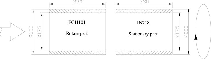
Figure 1. Illustration of the workpiece dimensions prior to welding (units: mm).
HWI-IFW-600 inertia friction welding machine was used with 6000 kN maximum welding force, 650 rpm maximum spindle speed and 8,000 kg m2 maximum rotational inertia. The welding parameter incorporated rotary inertia of 6,000 kg m2;rotational speeds of 450 rpm; upsetting pressure of 297 MPa and upsetting time of 60s. Following the welding process, the weld ring undergoes machining to achieve test specimens. Subsequently, the specimens were subjected to 720°C × 3.5 h aging heat treatment to optimize its mechanical properties.
2.2 Microstructure characterization and mechanical properties test
Figure 2 illustrates the sample cutting positions and types. For microstructural analysis, tensile testing, and fatigue testing, preparations included two specimens with a thickness of 10 mm and eight rods with a diameter of 12 mm, all obtained via wire-electrode cutting. One of the metallographic specimens was retained in as-welded condition to provide a basis for comparative analysis with the aging-treatment samples.
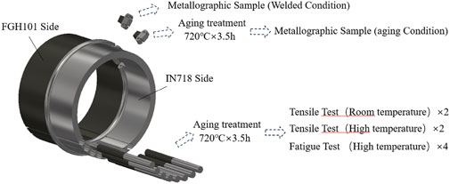
Figure 2. Sampling positionTest sample location and (unit: mm).
The specific conditions of the mechanical properties test are detailed in Table 1. The metallographic specimens were ground to 2,000 grit using abrasive paper and subsequently polished. The γ phase was removed using an appropriate etchant, and electrolytic etching was conducted at a voltage of 5 V for a duration of 3–5 s.
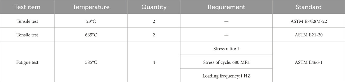
Table 1. Mechanical properties test conditions.
The present study employed optical microscopy (OM) analysis utilising a VHX7000 extended depth of field microscope for the purpose of investigating the interface microstructure. Additionally, a TESCAN MAIA3 scanning electron microscope was used to conduct a Scanning Electron Microscope (SEM) analysis with a view to examining the distribution of precipitated phases and the fracture morphology of fatigue specimens. Microhardness tests were carried out to the faying interface. The loading force used was 9.807N, and the pressure was maintained for a period of 30 s.
3 Results
3.1 Macrostructure and microhardness
Figure 3 illustrates the as-welded (AW) macroscopic morphology and microhardness distribution. During inertia friction welding, the intense heat-induced plastic deformation causes significant plastic flow in IN718 side, resulting in the formation of symmetrical ear-shaped flash. Conversely, the FGH101 side undergoes only minor upsetting. Simultaneously, the weld interface does not exhibit a completely flat characteristic but instead shows a wavy distribution, which is associated with the heat dissipation conditions along the surface of the workpieces during the welding process.
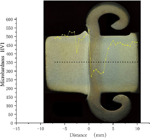
Figure 3. Macroscopic morphology and microhardness distribution of AW.
The microhardness distribution map clearly delineates the size distribution of the heat-affected zone (HAZ) in the welded joint. The highest hardness is observed at the weld interface, due to the residual compressive stress induced by the applied pressure and cooling contraction during the welding process.
In the near-interface HAZ of the IN718 side, the microhardness drops sharply, attributed to the re-dissolution of strengthening phases caused by the frictional heat. As the HAZ transitions into the base material, the hardness gradually returns to the base material level.
Compared to the IN718 side, the microhardness distribution on the FGH101 side does not exhibit a pronounced valley region. Instead, it quickly recovers to the base material level after an initial decrease, indicating better thermal stability of the strengthening phases. These observations indicate that both IN718 and FGH101 near the weld interface have undergone significant dissolution and reprecipitation of strengthening phases. This behavior will be further discussed in the microstructure analysis section.
Figure 4 illustrates the aging condition macroscopic morphology and microhardness distribution. The aged welding joints exhibit higher hardness levels compared to the as-welded condition. Notably, the hardness valley in the HAZ of the IN718 side disappears, while a hardness peak emerges in the HAZ of the FGH101 side. These observations indicate that both materials near the weld interface have undergone significant dissolution and reprecipitation of strengthening phases. This behavior will be further discussed in the microstructure analysis section.
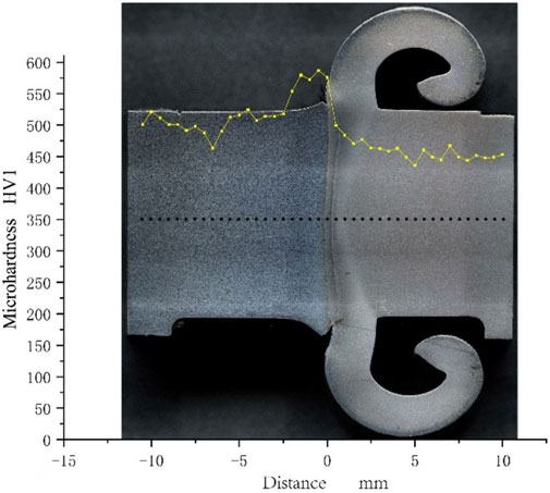
Figure 4. Macroscopic morphology and microhardness distribution of aging condition.
3.2 SEM analysis
In Figure 5, The SEM analysis of the interfacial microstructure reveals that, in the AW condition, both materials adjacent to the friction interface undergo significant plastic deformation due to welding. The peak temperature during the welding process can reach approximately 1,200°C, which leads to the redissolution of most original γ′ phases back into the matrix. The material near and at the interface experiences a dramatic increase in dislocation density due to intense thermomechanical coupling effects. Concurrently, recrystallization occurs; however, the dislocation density sharply decreases under the residual heat from the forging process. Due to the rapid cooling rate, substructures remain after the weld seam has fully cooled.
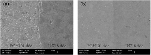
Figure 5. Microstructure of welding joint interface under different conditions. (A) as-welded; (B) aging condition.
Compared to the IN718 side, the FGH101 side exhibits more pronounced grain boundary morphology near the interface. Under aging conditions, further heat and reaction time are provided, allowing for the release of energy stored post-welding. On the FGH101 side, this results in the precipitation of fine tertiary spherical γ′ phases. In contrast, on the IN718 side, continuous δ phase precipitates gradually along the grain boundaries, and fine γ'' phases precipitate within the grains.
The microstructural morphology of the IN718 side across various regions of the dissimilar high-temperature alloy inertia friction weld joints between FGH101 and IN718, under different post-weld heat treatment regimes, is illustrated in Figure 6. The analysis reveals that, within the same heat treatment regime, as the observation location approaches the weld seam, the volume fraction of large γ′ precipitates progressively decreases until it vanishes. This phenomenon is attributed to the redissolution of strengthening phases caused by the frictional heat during welding. In the as-welded (AW) condition, the heat-affected zone exhibits a critical state where large strengthening phases are on the verge of redissolution.
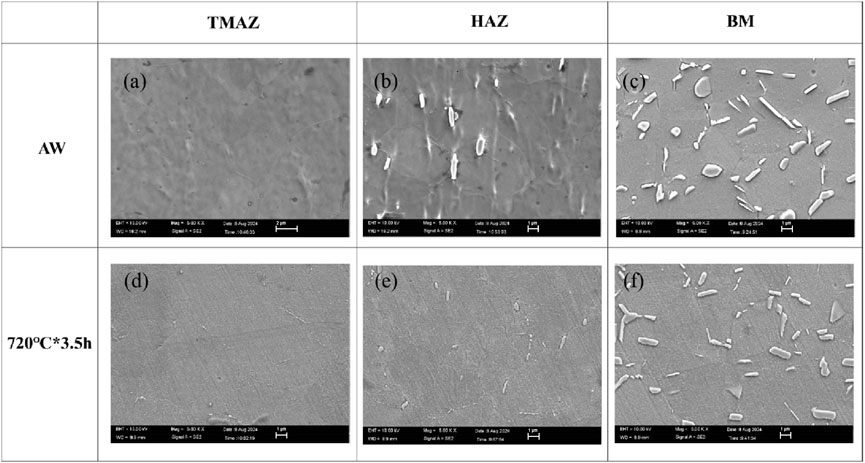
Figure 6. Microstructure of IN718 side. (A) The thermo-mechanically affected zone in as-welded state; (B) Heat-affected zone in as-welded state; (C) Base Metal zone in as-welded state; (D) Thermal Mechanical affected zone in aging state; (E) Heat-affected zone in aging state; (F) Base Metal zone in aging state.
Post-weld heat treatments facilitate the gradual precipitation of fine γ'' phases near the weld seam, which contributes to an enhancement in joint strength. It is noteworthy that no γ'' phase precipitation was observed in any region of the IN718 side under the AW condition. Consequently, at positions distant from the weld centerline, the microstructure of AW specimens consists of γ and γ′ phases, whereas that of the aged specimens comprises γ, γ′, and γ'' phases.
Further analysis indicates that the absence of γ'' phase in the AW condition is likely due to insufficient thermal energy for the nucleation and growth of this phase. The post-weld heat treatments provide the necessary conditions for γ'' phase formation, thereby enhancing the mechanical properties of the weld joint. The transformation of the microstructure with distance from the weld seam reflects the complex interplay between temperature gradients and cooling rates experienced during welding and subsequent heat treatments. This transition not only affects the distribution and size of precipitates but also significantly influences the overall performance and durability of the weld joint.
The microstructural morphology of the FGH101 side across different regions of welding joints between FGH101 and IN718, is depicted in Figure 7. The analysis reveals that,within the same condition, as the observation location approaches the welding seam, the volume fraction of fine γ′ precipitates gradually decreases until it becomes negligible. This trend is indicative of the redissolution of γ′ phases due to elevated temperatures during welding.
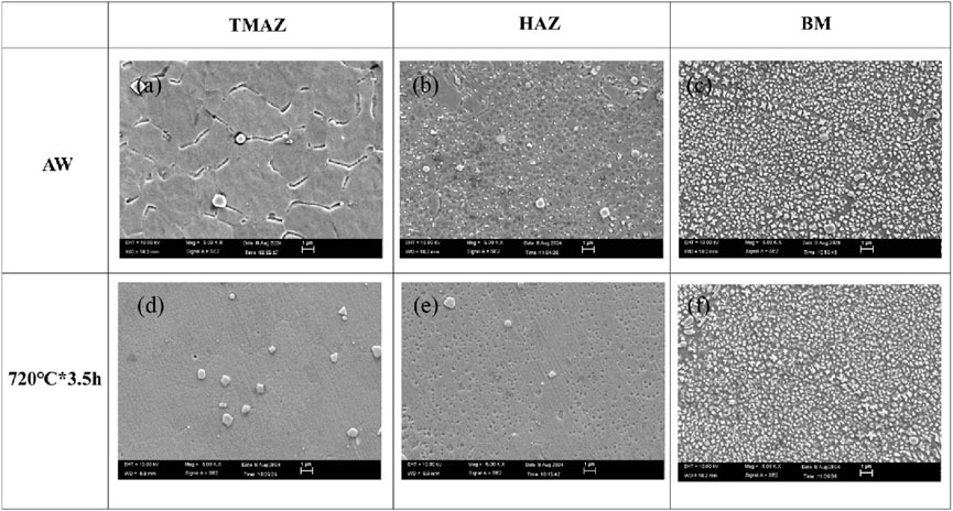
Figure 7. Microstructure of FGH101 side. (A) The thermo-mechanically affected zone in as-welded state; (B) Heat-affected zone in as-welded state; (C) Base Metal zone in as-welded state; (D) Thermal Mechanical affected zone in aging state; (E) Heat affected zone in aging state; (F) Base Metal zone in aging state.
In theTMAZ region, the substructure stored energy varies with different heat treatment regimes, allowing for the continuation of recrystallization processes. As a result, the grain boundaries of FGH101 become increasingly straightened, and fine tertiary γ′ precipitates start to emerge. The progression of recrystallization and precipitation hardening is influenced by the specific heat treatment parameters, which dictate the rate at which stored energy is released and new phases are formed.
Further analysis indicates that the evolution of the microstructure in the near-weld region is a complex function of temperature gradients, cooling rates, and the duration of heat exposure. These factors collectively determine the extent of recrystallization and the characteristics of precipitate formation.
3.3 Mechanical properties and fatigue fracture analysis
The tensile test results of FGH101+IN718 inertial friction welding joints are shown in Figure 8. At room temperature, the welding joints demonstrated impressive strength characteristics, with the average yield strength (YS) and average ultimate tensile strength (UTS) reaching 1,204 MPa and 1,467 MPa, respectively. Notably, all specimens exhibited plastic fracture within the IN718 base metal side, accompanied by evident necking. This indicates that the welds maintained sufficient ductility to deform plastically before failure.
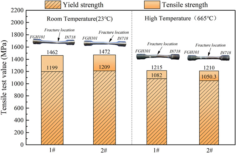
Figure 8. Tensile test results and fracture position.
In high-temperature tests conducted at 665°C, the welded joints showed a decrease in strength properties compared to room temperature, with average YS values around 1,066.1 MPa and average UTS approximately 1,212.5 MPa. Importantly, failures occurred within the weld zone itself, without the presence of necking. This suggests a shift in the failure mode at elevated temperatures, likely due to changes in material properties or residual stresses within the weld.
The high-temperature fatigue performance of the FGH101+IN718 welded joints in Figure 9 reveals significant insights into their durability under cyclic loading conditions at elevated temperatures. The specimens exhibited varying lifespans, with notable differences in both the number of cycles to failure and the location of fracture.

Figure 9. Fatigue test results and fracture position.
Specimens 1# and 2# experienced fewer cycles before failure, reaching 106,752 and 175,684 cycles, respectively. Both specimens ultimately fractured at the threaded section on the IN718 side. This suggests that the threaded region may act as a stress concentrator, leading to earlier initiation of cracks and subsequent failure. The relatively lower cycle counts could also indicate that this area is more susceptible to microstructural changes or residual stresses, which may accelerate crack propagation.
In contrast, Specimens 3 and 4 demonstrated significantly higher fatigue life, enduring 253,879 and 230,337 cycles, respectively. Notably, these specimens failed in the FGH101 base metal, far from the weld center. This indicates that the weld itself and its immediate vicinity did not serve as the primary source of fatigue initiation under these testing conditions. Instead, the failure mode suggests that the material properties of the FGH101 side played a crucial role in determining the joint’s fatigue life.
Further SEM fractographic analysis was conducted on the FGH101 side of specimen 4# to investigate the fatigue fracture surface, as illustrated in Figure 10. Figure 10A provides an overview of the entire fracture surface. Upon closer examination, it is evident that the crack initiation zone is located at the top center of the fracture cross-section (Figure 10C). This region exhibits characteristics of intergranular brittle fracture, indicative of a failure mode where cracks propagate along grain boundaries. In Figure 10E, clear fatigue striations and a few dispersed strengthening phase particles are observable, highlighting the cyclic nature of the loading conditions experienced by the material.
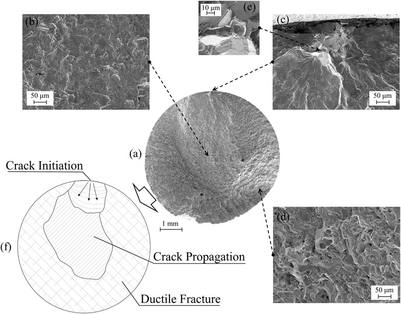
Figure 10. Fatigue fracture morphology of sample 4#. (A) Morphology of Overall fracture; (B) Morphology of crack propagation zone; (C) Morphology of crack initiation zone; (D) Morphology of ductile fracture zone; (E) Local enlarged view of crack initiation zone; (F) Distribution of different fracture zone.
The central region of the fracture surface represents the crack propagation zone, which, as shown in Figure 10B, displays a mixed-mode fracture pattern. This suggests that both ductile and brittle mechanisms were active during crack propagation, likely influenced by varying stress states and microstructural features encountered by the advancing crack front.
The sides and lower portion of the fracture surface correspond to the ductile fracture zone, characterized by a typical dimple morphology, as seen in Figure 10D. The presence of these dimples indicates a significant amount of plastic deformation prior to final rupture, consistent with a ductile tearing mechanism. This region’s morphology suggests that void nucleation, growth, and coalescence played a critical role in the fracture process.
4 Discussion
During inertia friction welding (IFW), intense plastic deformation and high temperatures lead to significant changes in microstructure near the weld interface. Symmetrical ear-shaped flash forms on the IN718 side due to extensive plastic flow, while only minor upsetting is observed on the FGH101 side. In the as-welded condition, both alloys experience a marked decrease in γ′ precipitates near the weld interface because of their redissolution into the matrix at peak temperatures around 1,200°C. This leads to a sharp drop in microhardness within the heat-affected zone (HAZ) of IN718 but quicker recovery to base material levels on FGH101, indicating superior thermal stability.
Post-weld aging treatments enhance hardness and strength by promoting the precipitation of fine tertiary spherical γ′ phases on the FGH101 side and continuous δ phase along grain boundaries with fine γ'' phases within grains on the IN718 side. Room temperature tensile tests reveal impressive joint strength with failures occurring plastically within the IN718 base metal. However, at elevated temperatures, failure shifts to the weld zone without necking, suggesting altered failure modes. Fatigue testing shows varying lifespans, with failures initiated either at stress concentrators like threaded sections or within the FGH101 base metal far from the weld center, emphasizing the role of microstructure on joint performance. Scanning electron microscope (SEM) analysis confirms mixed-mode fracture patterns, highlighting the complex relationship between microstructure, mechanical properties, and fatigue behavior. These findings provide critical insights for optimizing IFW parameters to achieve superior weld quality and reliability in aerospace engine components.
5 Conclusion
(1) During inertia friction welding (IFW), significant microstructural changes occur near the weld interface of FGH101 and IN718. FGH101 demonstrates superior thermal stability, with hardness in the heat-affected zone (HAZ) quickly recovering to base material levels, whereas IN718 experiences a sharp drop in hardness in the same region. This indicates that FGH101 is more resistant to high temperatures during welding, contributing to enhanced joint strength.
(2) Post-weld aging treatments promote the precipitation of fine tertiary spherical γ′ phases on the FGH101 side and continuous δ phases along with fine γ'' phases within grains on the IN718 side, significantly enhancing the hardness and mechanical properties of the joint. This highlights the importance of appropriate heat treatment in optimizing the mechanical characteristics of dissimilar superalloy welds.
(3) Tensile tests reveal that at room temperature, failure primarily occurs through plastic deformation within the IN718 base metal; however, at elevated temperatures, failure shifts to the weld zone without noticeable necking. Fatigue tests show varied lifespans, with fracture locations appearing either at stress concentrators like threaded sections or within the FGH101 base metal far from the weld center. This underscores the critical influence of microstructure on failure mechanisms under different loading conditions.
Data availability statement
The original contributions presented in the study are included in the article/supplementary material, further inquiries can be directed to the corresponding author.
Author contributions
JZ: Writing–review and editing. YZ: Writing–original draft. FQ: Conceptualization, Writing–original draft. XZ: Data curation, Writing–original draft. HW: Investigation, Writing–review and editing. ZL: Methodology, Writing–review and editing. WZ: Validation, Writing–review and editing. CH: Project administration, Writing–review and editing. CZ: Funding acquisition, Writing–review and editing.
Funding
The author(s) declare that no financial support was received for the research, authorship, and/or publication of this article.
Conflict of interest
Authors JZ, YZ, FQ, XZ, HW, ZL, WZ, CH, and CZ were employed by Harbin Welding Institute Limited Company. Author YZ was employed by AECC Commercial Aircraft Engine Co., Ltd.
Generative AI statement
The author(s) declare that no Generative AI was used in the creation of this manuscript.
Publisher’s note
All claims expressed in this article are solely those of the authors and do not necessarily represent those of their affiliated organizations, or those of the publisher, the editors and the reviewers. Any product that may be evaluated in this article, or claim that may be made by its manufacturer, is not guaranteed or endorsed by the publisher.
References
Chang-an, L., Qin, G., Wang, H., and Peihao, G. (2022). Constitutive modeling and dynamic recrystallization mechanism elaboration of FGH96 with severe hot deformation. J. Mater. Res. Technol. 21, 2947–2964. doi:10.1016/j.jmrt.2022.10.103
Daus, Li, Baxter, B., Bowen, , Bray, S., and Bowen, P. (2007). Mechanical and microstructural assessments of RR1000 to IN718 inertia welds – effects of welding parameters. Mater. Sci. Technol. 23 (12), 1424–1432. doi:10.1179/174328407X243997
Grant, B., Preuss, M., Withers, P. J., Baxter, G., and Rowlson, M. (2009). Finite element process modelling of inertia friction welding advanced nickel-based superalloy. Mater. Sci. and Eng. 513-514, A366–A375. doi:10.1016/j.msea.2009.02.005
Han, X., Zhu, G., Tan, Q., and Sun, B. (2023). Effect of semi-aging heat treatment on microstructure and mechanical properties of an inertia friction welded joint of FGH96 powder metallurgy superalloy. Metals 13 (3), 632. doi:10.3390/met13030632
Iqbal, N., Rolph, J., Moat, R., Hughes, D., Hofmann, M., Kelleher, J., et al. (2011). A comparison of residual stress development in inertia friction welded fine grain and coarse grain nickel-base superalloy. Metallurgical Mater. Trans. 42 (13), 4056–4063. doi:10.1007/s11661-011-0802-0
Liu, C., Zhu, H. -Y., and Dong, C. -L. (2014). Internal residual stress measurement on inertia friction welding of nickel-based superalloy. Sci. Technol. Weld. Join. 19 (5), 408–415. doi:10.1179/1362171814Y.0000000206
Mahaffey, D. W., Senkov, O. N., Shivpuri, R., and Semiatin, S. L. (2016). Effect of process variables on the inertia friction welding of superalloys LSHR and mar-m247. Metallurgical Mater. Trans. 47 (8), 3981–4000. doi:10.1007/s11661-016-3600-x
Nie, L., Zhang, L., Zhu, Z., and Xu, W. (2014). Microstructure evolution modeling of FGH96 superalloy during inertia friction welding process. Finite Elem. Analysis and Des. 80, 63–68. doi:10.1016/j.finel.2013.10.007
Oluwasegun, K. M., Olawale, J. O., Ige, O. O., Shittu, M. D., Adeleke, A. A., and Malomo, B. O. (2014). Microstructural characterization of thermomechanical and heat-affected zones of an inertia friction welded Astroloy. J. Mater. Eng. Perform. 23 (8), 2834–2846. doi:10.1007/s11665-014-1067-8
Tang, T., Shi, Q., Zhang, C., Liang, Wu, Zhou, J., Zhang, G., et al. (2024). Elucidating the in-process interfacial friction regime and thermal responses during inertia friction welding of dissimilar superalloys. J. Mater. Res. Technol. 30, 1650–1661. doi:10.1016/j.jmrt.2024.03.210
Tiley, J. S., Mahaffey, D. W., Alam, T., Rojhirunsakool, T., Senkov, O., Parthasarthy, T., et al. (2016). Strengthening mechanisms in an inertia friction welded nickel-base superalloy. Mater. Sci. and Eng. 662, A26–A35. doi:10.1016/j.msea.2016.03.030
Wang, F. F., Li, W. Y., Li, J. L., and Vairis, A. (2014). Process parameter analysis of inertia friction welding nickel-based superalloy. Int. J. Adv. Manuf. Technol. 71 (9-12), 1909–1918. doi:10.1007/s00170-013-5569-6
Wang, J., Xie, Y., Meng, X., Zhao, Y., Li, J., Sun, S., et al. (2024). Wire-based friction stir additive manufacturing towards isotropic high-strength-ductility Al-Mg alloys. Virtual Phys. Prototyp. 19. doi:10.1080/17452759.2024.2417369
Yang, J., Li, J., and Jin, F. (2019b). Effect of welding parameters on high-temperature tensile and fatigue properties of FGH96 inertia friction welded joints. Weld. World 63 (4), 1033–1053. doi:10.1007/s40194-019-00740-1
Yang, J., Li, J., Xiong, J., Yan, W., and Jin, F. (2019a). Effect of solution treatment temperature on the γ′precipitation distribution, high temperature tensile and fatigue properties of FGH96 joints prepared by inertia friction welding. Mater. Res. Express 11, 1165g9. doi:10.1088/2053-1591/ab4d14
Zhang, C., Shen, W., Zhang, L., Xia, Y., and Li, R. (2017). The microstructure and gamma prime distributions in inertia friction welded joint of P/M superalloy FGH96. J. Mater. Eng. Perform. 26 (4), 1581–1588. doi:10.1007/s11665-017-2601-2
Zhang, L., Liu, C., Qi, S., Yu, Y., Zhu, W., Qu, S., et al. (2004a). Numerical simulation of inertia friction welding process of GH4169 alloy. J. de Physique IV (Proceedings), 681–687. doi:10.1051/jp4:2004120078
Zhang, S., Xiao-Long, Li, Jian-Feng, Z., Lu, Z., Zhu, M.-L., and Fu-Zhen, X. (2023). High cycle fatigue behavior of inertia friction welded joint of FGH96 alloy at high temperature. Int. J. Fatigue 176, 107870. doi:10.1016/j.ijfatigue.2023.107870
Zhang, Y., Peng, Z., Tong, Y., Dong, H., Zhou, J., Feng, Q., et al. (2024c). Microstructure and mechanical properties of powder metallurgy superalloy joints welded by inertia friction welding. Materials 17 (6), 1342. doi:10.3390/ma17061342
Keywords: dissimilar metal welding, inertial friction welding, aeroengine, microstructure, superalloy
Citation: Zhou J, Zhang Y, Qin F, Zhang X, Wang H, Liu Z, Zhang W, Huang C and Zhang C (2025) Analysis of microstructural evolution and mechanical properties of FGH101 powder superalloy and IN718 deformed superalloy via inertia friction welding. Front. Mater. 11:1544584. doi: 10.3389/fmats.2024.1544584
Received: 13 December 2024; Accepted: 26 December 2024;
Published: 30 January 2025.
Edited by:
Xiangchen Meng, Harbin Institute of Technology, ChinaReviewed by:
Pavlo Maruschak, Ternopil Ivan Pului National Technical University, UkraineGuoliang Qin, Shandong University, China
H. Dong, Dalian University of Technology, China
Copyright © 2025 Zhou, Zhang, Qin, Zhang, Wang, Liu, Zhang, Huang and Zhang. This is an open-access article distributed under the terms of the Creative Commons Attribution License (CC BY). The use, distribution or reproduction in other forums is permitted, provided the original author(s) and the copyright owner(s) are credited and that the original publication in this journal is cited, in accordance with accepted academic practice. No use, distribution or reproduction is permitted which does not comply with these terms.
*Correspondence: Chunbo Zhang, emhhbmdjYmNiQDE2My5jb20=