- 1Institute for Manufacturing Technologies of Ceramic Components and Composites (IFKB), University of Stuttgart, Stuttgart, Germany
- 2G.E.R.N. Center of Tissue Replacement, Regeneration and Neogenesis, Department of Orthopedics and Trauma Surgery, Faculty of Medicine, Albert-Ludwigs-University of Freiburg, Freiburg, Germany
- 3Federal Institute for Materials Research and Testing (BAM), Berlin, Germany
Enhancing osseointegration, the process by which medical implants securely bond to bone, is crucial for improving patient outcomes in orthopedics and dental surgery. Calcium alkali orthophosphates, with their superior bioactivity, resorbability, and chemical resemblance to bone minerals, have emerged as promising candidates for implant coatings. These materials offer improved solubility and lower melting points due to the substitution of calcium with potassium and sodium, along with the addition of magnesium oxide. This study investigates GB14 calcium alkali orthophosphate coatings applied via High Velocity Suspension Flame Spraying (HVSFS), a technique that enables precise control over coating properties. A porosity target of >10% was set to promote bone growth, and we achieved porosities up to 13%, ensuring better cell penetration and stability at the implant-bone interface. Coatings were produced using different gas parameters and distances, with their microstructure and phase composition analyzed using scanning electron microscope (SEM), Vickers hardness testing and X-ray diffraction (XRD). Additionally, roughness and porosity were also assessed. Different coating’s microstructures were achieved by varying stand-off distance and gas parameters. Increasing stand-off distance while reducing gas stoichiometry enabled the production of calcium alkali orthophosphate coatings with fewer cracks, higher porosity and a hardness level comparable to that of state-of-the-art tricalcium phosphate (TCP) coatings. The sample with optimized properties in terms of achieved microstructure and topography was selected for in vitro testing using MG63 osteosarcoma cells to evaluate cell proliferation and adhesion. WST (I) assay, LDH assay, and live/dead staining confirmed the biocompatibility of the coatings, highlighting the potential of HVSFS to enhance osseointegration and outperform conventional methods in implantology. No relevant cytotoxicity could be shown and cells show a good proliferation over time. These results highlight thus the potential of HVSFS to produce thin, bioactive and resorbable coatings to enhance osseointegration.
1 Introduction
The development of advanced materials for medical implants is critical to improving patient outcomes, particularly in orthopedics and dental surgery. One of the key challenges in implantology is achieving optimal osseointegration, the process by which an implant becomes securely anchored to the surrounding bone (Zhang et al., 2014; Heimann, 2018; Amirtharaj Mosas et al., 2022; Nikolova and Apostolova, 2022). To improve this process, coatings that promote bone cell attachment and growth, such as bioceramics, are of great interest (Heimann, 2013; 2024; Chen et al., 2020; Goldmann, 2021; Molaei et al., 2021; Amirtharaj Mosas et al., 2022). Bioceramics first appeared in the 1920s and have been developed primarily since the 1960s. These materials are now state of the art in joint replacement prosthetics (Best et al., 2008). They can be classified as “bioinert” or “bioactive” and they can be resorbable or non-resorbable (Best et al., 2008).
Besides established materials such as tricalcium phosphate (TCP, Ca3(PO4)2) and bioglass (BG45S5), calcium alkali orthophosphates have been developed. Aiming to increase the solubility compared to TCP, Berger et al. developed calcium alkali orthophosphate materials based on the main crystalline phase Ca2KNa(PO4)2, replacing one of the calcium atoms by a potassium and a sodium atom (Berger et al., 1995). Because of their excellent biocompatibility, bioactivity, and chemical similarity to natural bone mineral, calcium alkali orthophosphates have emerged as promising candidates for coating medical implants (Bernstein et al., 2008; Bernstein et al., 2017). In addition, they can facilitate bone regeneration by providing a favourable environment for bone cell attachment, proliferation, and differentiation (Berger et al., 1995; Knabe et al., 1998).GB14 is based on the main crystalline phase Ca2KNa(PO4)2 and an additional amorphous portion of magnesium potassium phosphate with the following composition (wt%): CaO (30.67 wt%), P2O5 (43.14 wt%), Na2O (9.42 wt%), K2O (14.32 wt%), MgO (2.45 wt%) (Berger et al., 1995). GB14 bone cements and substitutes have already been produced and characterized, obtaining excellent results (Knabe et al., 1998; Knabe et al., 2004; Knabe et al., 2023).When applied as a coating, calcium alkali orthophosphates can significantly enhance the osseointegration process, reducing the risk of implant failure and improving patient outcomes (Bernstein et al., 2017). High Velocity Suspension Flame Spraying (HVSFS) enables the deposition of dense, well-adhered coatings with tunable microstructures, making it an ideal method for applying calcium alkali orthophosphate coatings to implants (Bernstein et al., 2017; Burtscher et al., 2019; Przybilla et al., 2023). The advantages of HVSFS, such as the ability to produce thin coatings with controlled porosity and surface roughness, can further enhance the bioactivity of the implant surface and promote faster and more effective osseointegration (Killinger et al., 2006; Bolelli et al., 2009; Bernstein et al., 2017; Toma et al., 2021; Blum et al., 2022; Lanzino et al., 2024).
In this article, we will explore the potential of GB14 calcium-alkali orthophosphate, resorbable coatings applied by HVSFS to medical implants to promote osseointegration. A porosity target of >10% is set to enhance bone growth and ensure sufficient stability at the interface through cell penetration within the pores (Cao and Hench, 1996). Since GB14 is resorbable, the porous coating is supposed to degrade, be absorbed by the body and replaced by the new bone tissue over time. Additionally, we aim to highlight the advantages of using HVSFS over conventional coating methods for calcium phosphate (CaP) materials, such as atmospheric plasma spraying (APS), electrochemical deposition and sol-gel processes (Guner and Meran, 2019; Ishikawa and Kareiva, 2020; Jaafar et al., 2020; Heimann, 2024). Starting from the production of GB14 powder, we analyzed coatings sprayed under different gas parameters and distances. The microstructure and phase composition of these coatings were examined, and the sample with the best results was selected for in vitro testing. For these samples, we evaluated the interaction with MG63 cells (an osteosarcoma cell line commonly used as an in vitro model to evaluate the proliferation and adhesion of bone cells on new biomaterials). WST (I) assay, LDH assay and live/dead staining were performed.
2 Materials and methods
2.1 Materials
GB14 based on the main crystalline phase Ca2KNa(PO4)2 with an average particle size of 33 μm was provided by Federal Institute for Materials Research and Testing (BAM), Berlin Lichterfelde, Germany.
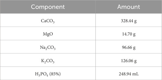
The material was prepared in small batches using the components as listed in Table 1.
For each single batch, the powders were weighed and mixed with a Turbula shaker (Typ T2F, Willy A. Bachofen AG Maschinenfabrik, Muttenz, Switzerland). Subsequently, the phosphoric acid was added in small steps with constant stirring to achieve a homogeneous distribution. The material was dried at 100°C, calcinated at 400°C in Al2O3 crucibles and processed with a pestle after each step. Combined batches were melted at about 1,580°C in an induction furnace (EMA-TEC GmbH 2002, Sondershausen, Germany), cast on a steel block, crushed with a jaw crusher (Type 8,850 Zirkon, Retsch GmbH, Haan, Germany) and milled with a vibrating mill (Pulverisette, Fritsch GmbH, Idar-Oberstein, Germany).
2.2 Suspension and coating deposition
2.2.1 Suspension
The GB14 raw powder exhibited a d90 of 72.7 µm. Given that particle sizes of this magnitude presented a risk of clogging the injection system during the spraying process, it was necessary to subject the powder to milling. For this purpose, the powder was introduced in a plastic vessel along with isopropanol and aluminium oxide (Al2O3) balls with a diameter d of 2 mm. The milling process was continued until achieving a d90 of 10 µm. In fact, in previous works it was found out, that such particle size allows the production of homogeneous CaP coatings (Lanzino et al., 2024).
Following the milling of the raw powder, water-based suspensions were prepared. The milled GB14 powder was added into the mixture of deionized (DI) water under continuous stirring, along with two stabilizing agents: 2 wt% of a hydrocolloid additive and 0.0015 wt% of a phosphonate-based additive.
2.2.2 Coating deposition
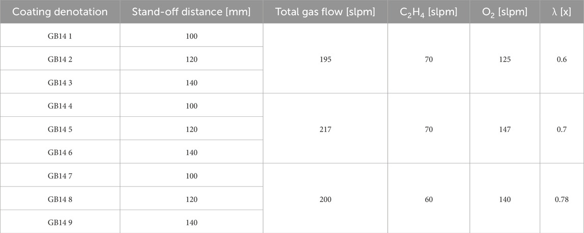
A parameter study was conducted to determine the optimal parameters for GB14 coatings. The target microstructure should be homogeneous, with a porosity >10% and moderate roughness to facilitate cells’ penetration and anchoring into the coating layers. A modified Top-Gun-G system (GTV Verschleißschutz, Luckenbach, Germany) was used for this work. The spray gun was mounted on a six-axis robot to perform controlled meander movement with an offset of 3 mm. The stand-off distance between spray gun and substrate was varied as well as the ethene (C2H4) and oxygen (O2) ratio, used for the combustion. Experiments were conducted on V2A stainless-steel substrates (Schmiedekult, rapa GmbH, Emmerich am Rhein, Germany, 50 × 50 × 3 mm). Before spraying, the surface of all samples was mechanically activated through grit-blasting, using F60 corundum with a pressure of 4 bar. Subsequently, the samples were cleaned with acetone in an ultrasonic bath and then weighed to determine the net weight of the substrate. The relative surface speed of the spray gun was set to 600 mm/s. A combustion chamber with the dimensions 22-8-135 was selected and used for all samples. To keep the thermal stress of the samples as low as possible, an axial pressurized air cooling with two nozzles at the left and right side of the spray gun axis was used and the samples were also cooled from behind during the whole spraying process. The influence of similar total gas flow by different ethene to oxygen ratio (λ) and stand-off distances was investigated. The suspension feed rate was kept at 80 g/min 10 passes were performed for all samples. All the parameters used for spraying can be seen in Table 2.
After selecting the sample with optimized properties, 12 samples on titanium (Ti) substrates (ARA-T Advance GmbH, Dinslaken, Germany, 10 × 10 × 3 mm) were produced to perform in vitro experiments. Here, the target thickness was set to 30 µm and only four passes of the torch over the Ti substrate were performed. This thickness was selected to achieve a thin coating that should be resorbed by the body within 6 months.
2.3 Coating characterization
2.3.1 SEM
For the characterization of the coatings, details of the microstructures were observed using a field-emission scanning electron microscope (SEM) S-800 (Hitachi High-Technologies Corporation, Tokyo, Japan) equipped with a sensor for backscattered electrons (BEC). Cross-section samples were sputtered with carbon before SEM examination. SEM images were additionally utilized to evaluate the coating porosity using image processing software (ImageJ 1.47v) with a contrast threshold for analysis. We performed the analysis on three SEM images at a magnification of ×800 and the “Minimum” threshold option was selected to avoid that supraparticles were considered as pores.
2.3.2 XRD
The phase composition of the coatings was analyzed by X-ray diffraction (XRD: X'Pert PRO, PANAlytical, Almelo, The Netherlands) using Cu–Kα radiation (wavelength: 0.1540598 nm). The diffraction patterns were collected in the 20°–70° 2θ range (step size: 0.02°; scan rate: 5 s/step).
2.3.3 Vickers microhardness
The coatings’ Vickers microhardness was measured on polished cross sections using a Fisherscope H100 (Helmut Fischer GmbH Institut für Elektronik und Messtechnik, Sindelfingen, Germany) hardness tester. HV 0.1 scale was used according to DIN EN ISO 14577 standard. The measurement was force regulated and the applied load of 980.665 mN was performed for 20 s with a load and release time of 5 s. For each sample, 13 imprints on the cross-section of the coating were made, the average hardness and its standard deviation were calculated.
2.3.4 Surface roughness
Coating roughness values Ra and Rz were investigated by tactile measurement with Mahr Perthometer (Mahr GmbH, Göttingen, Germany). The measurement was performed with a length of 17.5 mm and five single measurements according to DIN EN ISO 3274. For each coating, the values and standard deviation were determined taking the average values.
2.3.5 Optical microscopy
Coating microstructures were analyzed through an optical microscope MeF4M (Leica GmbH, Wetzlar, Germany) in bright field. Pictures were taken and analyzed by the Aquinto a4i analysis software (Olympus Europa SE and Co. KG, Hamburg, Germany). Coating thicknesses were characterized according to DIN EN ISO 1463:2021-08 by measuring fifteen single coating thickness values and respectively calculating average value and standard deviation.
2.3.6 Immersion in SBF
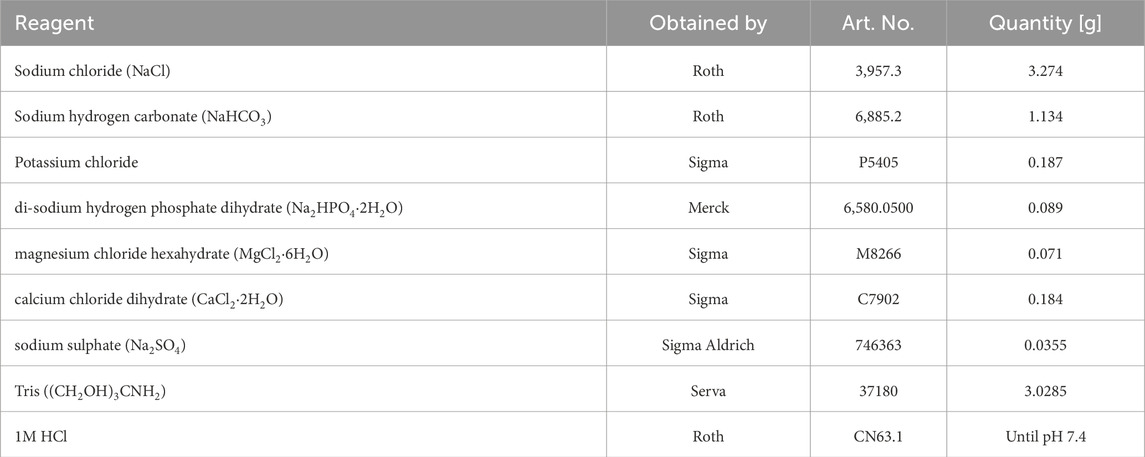
A 500 mL batch of simulated body fluid (SBF) was prepared according to the method described by (Jalota et al., 2008). The chemicals and their corresponding quantities used for SBF preparation are listed in Table 3. Deionized water was placed in a beaker and heated to 37°C on a magnetic stirrer. Each chemical was weighed using an electronic balance and added to the water in the order listed in Table 3. The pH of the solution was then measured using an electronic pH meter (Mettler Toledo, EL20, Columbus, OH, United States), and hydrochloric acid was gradually added until the pH reached 7.4. The beaker was covered with aluminum foil and stirred overnight. The next day, the solution was filtered through a 0.2 µm pore size filter and sealed under sterile conditions. A minimum of three samples were immersed in SBF for 14 days. Subsequently, the coating was examined using SEM (FEI Quanta 250 FEG with Oxford EDX) and compared with coatings that had not been incubated in SBF.
2.4 Biocompatibility testing in vitro
2.4.1 Preparation of the samples
Prior to the in vitro experiments, the samples were disinfected in 70% and 100% ethanol. After that they were autoclaved using the Systec D-Series Horizontal Benchtop autoclave (Thermo Fisher Scientific, Waltham, MA, United States).
2.4.2 Cell culture
For biocompatibility testing Osteosarcoma-cells MG-63 (ATCC, CRL 1427) were used. For culturing of the cells, a default medium, which was changed every other day, was used. This medium consisted of Dulbeccos Modified Eagle Medium DMEM/F-12 (DMEM/F12) (Gibco, Braunschweig, Germany), 10% fetal bovine serum (Biochrom, Berlin, Germany) and 1% Penicillin/Streptomycin (P/S) (Gibco, Braunschweig, Germany). To subculture the cells, Trypsin/Ethylene diamine tetracetic acid (Sigma-Aldrich, St. Louis, MO, United States) treatment was performed two times a week. The cells were incubated in a humid chamber at 37°C and 5% CO2.
Biocompatibility testing was performed using 50,000 cells/75 µL per sample. Per test, 3 samples were used and the tests were repeated at least 3 times.
2.4.3 Cell proliferation (WST-I-Assay)
50,000 cells in 75 µL medium were seeded onto each sample. As a control, a Thermanox® cover slip was used. After incubating the samples at 37°C, 5% CO2 and 100% humidity for 2 h, 1 mL of the medium described earlier was added to each well. After 24 h of incubation, the medium was exchanged using a medium which consisted of DMEM/F-12, 1% P/S and 1% FBS. To prevent background absorption, a lower concentration of FBS was used than in the seeding medium. The cell proliferation Assay was performed on day 1, 3 and 7 after incubation. Therefore, each well was washed with PBS three times. After that, 600 µL of a solution consisting of DMEM/F-12, 1% P/S, 1% FBS and 10% WST solution (Roche, Mannheim, Germany) was added to each well. After 2 h of incubation at 37°C and 5% CO2, the absorbance was measured using a spectrometer (SpectroStar nano, BMG Labtech, Ortenberg, Germany) at 450 nm. To avoid photoactivation all steps were performed in the dark.
2.4.4 LDH-cytotoxicity assay
The cells were seeded onto the samples in the same manner as before. Additionally, a positive control (Triton X and cells, 100% cytotoxicity) and a negative control (cells only, 0% cytotoxicity) were used. Cytotoxicity measurements were performed on day 1, 3 and 7 after initial seeding. At the measuring time points, 3 × 100 µL from each well was added to 3 wells of a 96-well plate. To prepare the cytotoxicity detection kit solution (Roche, Mannheim, Germany), 1 part of the catalyst solution was added to 45 parts of staining solution. 100 μL of the staining solution was then added to each well. The plate was incubated in the dark for 30 min. After the incubation period, the absorbance was measured at 490 nm using a spectrometer.
2.4.5 Live/dead-assay
As described beforehand, 50,000 cells/75 µL were seeded onto the samples and Thermanox® cover slip as control. After 2 h of incubation at 37°C, 5% CO2 and 100% humidity, 1 mL of default medium was added to each well. Live/Dead staining was performed on day 1, 3 and 7. To prepare the staining solution, 2 mL of Dulbecco’s Phosphate Buffered Saline (DPBS) (Gibco, Grand Island, NE, United States) were mixed with 1 µL Calcein dye (PromoCell, Heidelberg, Germany) and 4 µL Ethidium homodimer III (PromoCell, Heidelberg, Germany). At the measuring time points, the samples were washed with DPBS to remove serum esterase activity. The samples were incubated in the staining solution for 10 min and evaluated using an Olympus fluorescence microscope (BX51, Olympus, Osaka, Japan). Three detailed images at ×10 magnification and 1 overview at ×5 magnification were taken.
2.5 Statistics
Data were expressed as mean ± standard deviation and subjected to one-way analysis of variance (ANOVA). Means were compared by Fisher LSD. A significance threshold of p < 0.05 was used. Calculations were performed using OriginPro 2023 SR1 (OriginLabs, Northampton, MA, United States).
3 Results
3.1 Suspension and coating characterization
Before the spraying process began, the raw powder was first characterized through XRD to determine its phase composition, as shown in Figure 6A. Following this characterization, the powder was milled according to the procedure described in the Material and Methods section. SEM images of the raw powder, as well as the powder after milling can be seen in Figures 1A, B. Figure 1C illustrates the particle size distribution of the powder both before and after milling. Initially, the particle size had a d90 value of 72.7 µm, which was reduced to a d90 of 10.1 µm. The raw powder exhibited a bimodal distribution with d10 = 4.0 µm, d50 = 32.9 µm, and d90 = 72.7 µm. After milling, the first peak remained unchanged but increased in volume, while the second one shifted to the left and decreased in volume, indicating an overall reduction in size. The milled powder’s new particle size distribution was d10 = 0.9 µm, d50 = 3.2 µm and d90 = 10.1 µm.
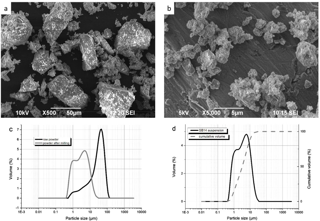
Figure 1. (A) SEM of GB14 raw powder; (B) SEM of GB14 after milling; (C) Particle size distribution of the GB14 powder before and after milling; (D) Particle size distribution of GB14 suspension.
The particle size distribution of the suspension used for spraying is shown in Figure 1D. The suspension had a d10 = 1 μm, d50 = 3.7 µm and d90 = 11.7 µm. It was successfully injected without any issues, and no clogging of the system was observed.
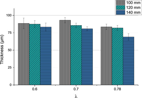
The coating thickness varied between 69.01 µm (GB14_9) and 93.06 µm (GB14_4). In Figure 2 can be observed that the thickness slightly decreases, when stand-off distance is increased.
Changing the ethene to oxygen ration (λ) does not significantly lead to a variation of the thickness. The coatings sprayed at λ = 0.78 seem to be thinner than at lower λ values. The sample sprayed at 140 mm and with the highest gas parameters (λ = 0.78) has the lowest coating thickness.
In the SEM images in Figures 3A–I the microstructure of the coatings can be seen.
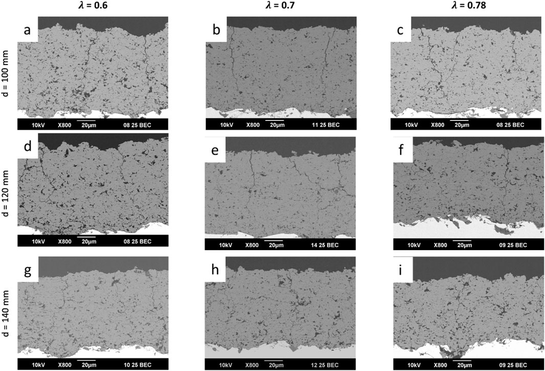
Figure 3. SEM images of all the sprayed GB14 coatings: (A) GB14_1; (B) GB14_2; (C) GB14_3; (D) GB14_4; (E) GB14_5; (F) GB14_6; (G) GB14_7; (H) GB14_8; (I) GB14_9.
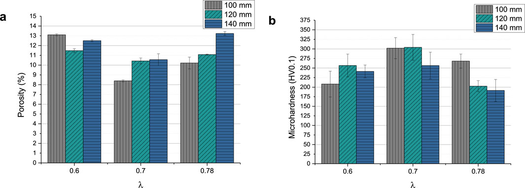
All coatings show vertical cracks and high porosity. For each set of samples sprayed with the same λ, the amount of cracks decreases with increasing stand-off distance. At the same time, with the exception of sample GB14_1 (Figure 3A), increasing stand-off distance results in higher porosity. The porosity of the coatings ranged between approximately 8% and 13% (see Figure 4A). GB14_1 and GB14_9 have the most porous microstructure (13% ± 0.08% and 13% ± 0.25%), followed by GB14_3 (12% ± 0.09%). The coatings sprayed at a stoichiometry ratio of λ = 0.7 and total gas flow of 217 slpm show a lower porosity compared to samples with else same parameters. In contrast, using a lower stoichiometry of λ = 0.6 appears to increase the porosity of the coating. The densest coating is sample GB14_4, coated with d = 100 mm and λ = 0.7 (8% ± 0.06%). Coatings sprayed with λ = 0.78 show a more pronounced crack network with predominantly smaller cracks as compared to those sprayed at λ = 0.7. Additionally, an increase in stand-off distance seems to improve particle melting.
Figure 4B shows the Vickers microhardness of the coatings, which ranges between 191.4 ± 28.81 HV0.1 (GB14_9) and 304.19 ± 33.67 HV0.1 (GB14_5). In this case, the total gas flow has the greatest impact on the results. The samples coated at λ = 0.7 and a total gas flow of 217 slpm show the highest microhardness. The coatings sprayed with the same gas parameters but at different distances, with the exception of sample GB14_7, have similar microhardness.
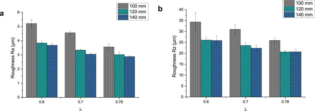
The roughness parameter Ra of the GB14 coatings is shown in Figure 5A. It ranges between 2.88 ± 0.06 µm (GB14_9) and 5.21 ± 0.3 µm (GB14_1). The Rz values, shown in Figure 5B, are between 20.68 ± 1.12 µm (GB14_9) and 34.31 ± 4.36 µm (GB14_1). The roughness increases with decreasing stand-off distance and at the same time with decreasing λ. GB14_1 has thus the roughest surface whereas GB14_9 has the smoothest surface. It is to be observed, that an increase of d from 100 mm to 120 mm significantly decreases Ra and Rz values, while a further change of the stand-off distance from 120 mm to 140 mm leads to less change in these values.
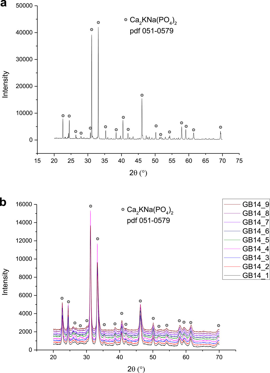
Figure 6 shows the XRD patterns of the phases observed in the GB14 raw powder and in the coatings. All the peaks observed in the GB14 powder are also present in the XRD patterns of the coatings and are of the main crystalline phase Ca2KNa(PO4)2 (reference pdf 051-0579). The samples exhibit similar patterns, with GB14_4 displaying higher intensities, suggesting that this coating is more crystalline than the other specimens. Coatings sprayed at d = 100 mm and d = 120 mm also show slightly higher intensities, particularly in the smaller peaks. However, it is challenging to quantify the differences between the samples, as the main peak intensities are similar.
After characterizing all samples, GB14_3 (λ = 0.6 and d = 140 mm) was selected for the in vitro experiments on Ti substrates because of the properties the coating showed. In fact, it exhibited fewer cracks, indicating lower residual tensile stress within the coating, and a porosity level >10% (12% ± 0.09%). Moreover, it showed a higher roughness Ra of 3.65 ± 0.12 µm compared to the other samples sprayed at d = 140 mm and a Vickers microhardness of 241.26 ± 16.65 HV0.1 in line with literature values for TCP coatings (see Discussion).
The thickness of the samples on Ti substrate was 27.11 ± 2.74 µm, the roughness parameter Ra was 4.02 ± 0.26 µm and Rz 25.25 ± 1.33 µm. The microstructure can be seen in Figure 7.
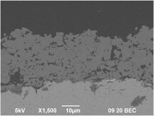
Figure 7. Microstructure of GB14_3 sample sprayed with optimized parameters on Ti substrate for in vitro tests.
3.1.1 Hydroxyapatite formation in simulated body fluid (SBF)
After 14 days of immersion in SBF, new crystalline structures develop on the surface of the samples (see Figures 8A, B). The crystalline structures can be found throughout the whole surface of the samples. Figure 8C shows XRD measurements before and after the in vitro experiments with MG63 cells. Here, the formation of hydroxyapatite (HAp) was revealed according to the International Centre for Diffraction Data (ICDD) 9-432.
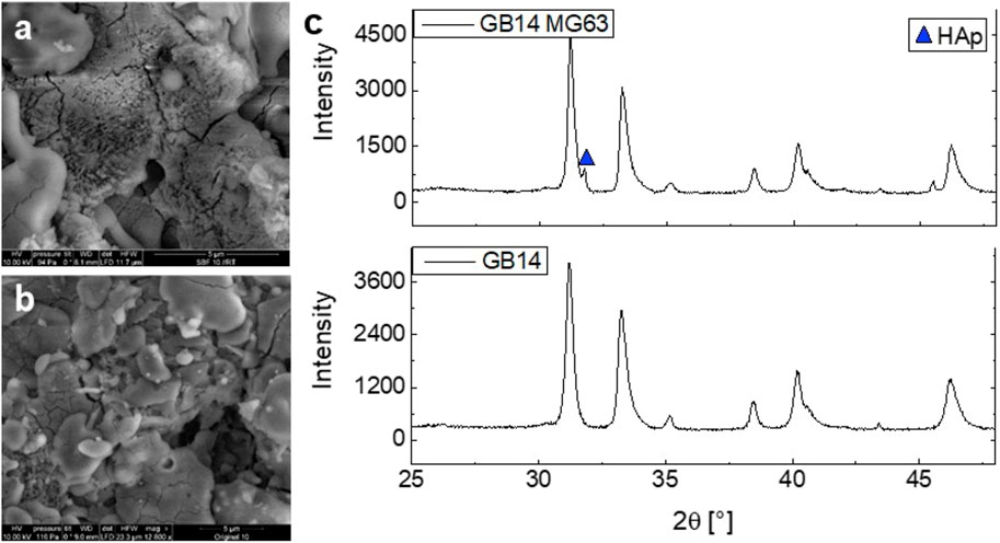
Figure 8. SEM imaging of GB14_3 sample on Ti before (A) and after (B) 14-day immersion in SBF. XRD measurement of GB14_3 sample before and after in vitro experiments with MG63 cells (C).
3.2 Biocompatibility testing in vitro
3.2.1 Cell proliferation
As Figure 9 shows, the cell proliferation of the GB14 sample increases significantly over 7 days. The cell proliferation is slightly lower compared to C-. Also, cells seem to proliferate significantly slower on the coating than on the Thermanox® cover slip.
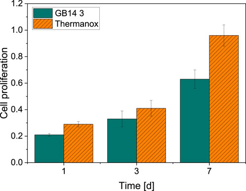
Figure 9. Cell proliferation on day 1, 3 and 7. Thermanox® cover slip with cells serves as a negative control. There is a significant increase in cell proliferation for MG63-cells on both GB14-coated samples as well as Thermanox® cover slip.
3.2.2 Cytotoxicity (LDH)
Compared to the negative control (0% cytotoxicity, cells only), no significant cytotoxicity can be observed for the coated GB14 sample after 24 h (3.38% ± 3.35%). After 48 h the cytotoxicity increases to 10.76% ± 9.54% and decreases after 72 h to 5.85% ± 5.42%. The course of the cytotoxicity of the GB14 coating in comparison to the negative control (0% cytotoxicity, cells only) and positive control (100% cytotoxicity, cells and Triton X) is summarized in Figure 10.
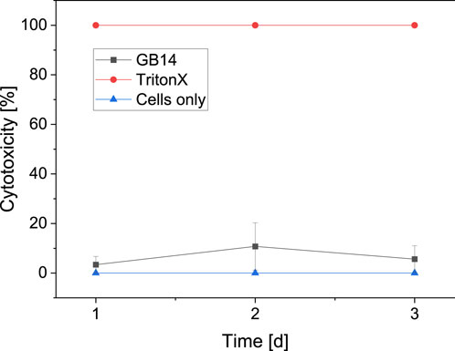
Figure 10. Cytotoxicity on day 1, 2 and 3. Triton X on cells serves as positive control (100% cytotoxicity), medium with cells serves as negative control (0% cytotoxicity). The cytotoxicity for the evaluated sample stays below 11%.
3.2.3 Live/dead assay
Figure 11 shows the live/dead cell counts over 7 days for the GB14 sample and the Thermanox® coverslip. The number of live cells on the coated sample is slightly lower than for C-. This difference is significant for day 1 and day 7. The number of dead cells is approximately the same for both samples.
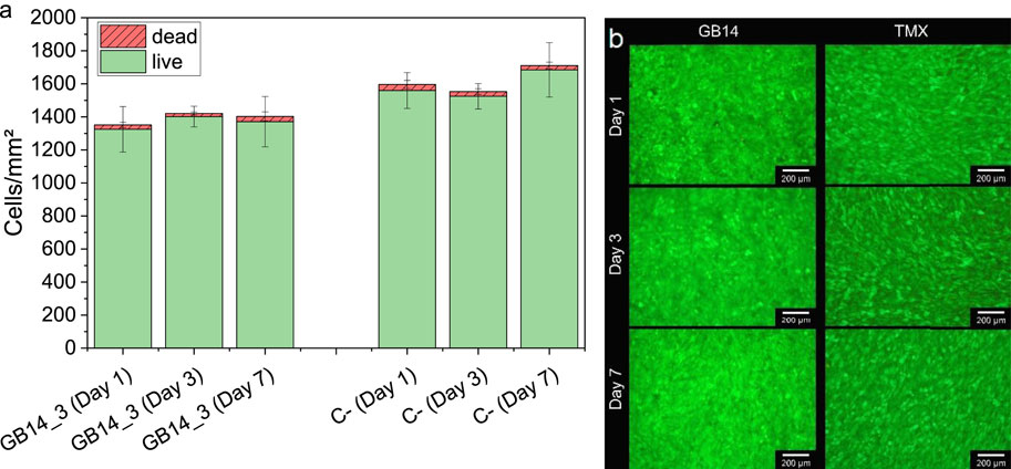
Figure 11. Live and dead cells on day 1, 3 and 7, (A) shows the cell count of live and dead cells, (B) shows the fluorescent images of the cells on the coating and the negative control. Cells on Thermanox® cover slip serve as a negative control (C-). Cell numbers on GB14 are similar to cell numbers on C-. GB14 does not significantly exhibit more dead cells than C-.
4 Discussion
4.1 Suspension and coatings
After milling, the raw powder’s particle size distribution was reduced to a d90 of 10.1 µm. In contrast, the produced suspension exhibited a d90 of 11.7 µm. This larger particle size in the suspension could be attributed to the presence of additives or small agglomerates. No clogging of the system was observed, suggesting that such distribution is suitable for the HVSFS process. These particles sizes have also been successfully used in previous studies (Lanzino et al., 2024).
The results of the thickness measurements indicate a decreasing coating thickness with increasing stand-off distance, a common behavior in thermal spraying. As the stand-off distance increases, the particles lose kinetic energy during the time spent in the flame, resulting in fewer particles adhering to the substrate or to subsequent coating layers. This leads to thinner coatings (Li et al., 2013; Fauchais et al., 2014; Katranidis et al., 2019; Rakhadilov et al., 2024).
As described in the results section, all coatings show numerous cracks. These cracks are predominantly vertical, suggesting they are unlikely to impair the coating quality (Bolelli et al., 2009). Horizontal cracks, however, indicate a decrease in cohesion strength between the layers (Vencl et al., 2011). Such coatings with horizontal cracks, sprayed at λ = 0.7, were therefore considered inadequate for medical applications (GB14_4, GB14_5 and GB14_6).
Increasing the stand-off distance reduced the cracks within the coating and led to a more porous microstructure, with the exception of sample GB14_1 (λ = 0.6 and d = 100 mm), which showed higher porosity than GB14_3 (λ = 0.6 and d = 140 mm). This likely resulted from the low flame temperature at λ = 0.6, combined with a short dwell time in the flame, preventing proper particle melting and causing a more porous coating. With increasing stand-off distance, on the contrary, the increasing dwell time caused significantly better melting and reduced the porosity from 100 mm to 120 mm.
In this study, coatings sprayed with λ = 0.7 and the maximum gas flow of 217 slpm exhibited the highest density and showed long vertical and horizontal cracks. This is probably due to the high gas flow and sufficiently high flame temperature, which led to well-molten particles, low porosity, and consequently high residual tensile stress, resulting in cracking. For coatings sprayed with λ = 0.78, a more pronounced crack network with predominantly smaller cracks formed compared to 0.7, likely due to higher flame temperature and therefore higher particle temperature at lower particle speeds.
In a previous study, GB14 coatings were applied using HVSFS, resulting in highly dense coatings (Bernstein et al., 2017). In the present study, we aimed to increase porosity to enhance resorbability. The porosity of the coatings in this paper ranged between 8% and 13%, aligning with literature values for ceramic coatings (Dalton and Cook, 1995; Ročňáková et al., 2018; Ganvir et al., 2021). In fact, higher porosity facilitates bone cell penetration into the coating, improving stability at the interface with the implant material (Cao and Hench, 1996).
The Vickers microhardness results showed an inverse correlation with porosity, as higher porosity leads to lower hardness values. Literature indicates that the microhardness of hydroxyapatite coatings depends on several microstructure properties, such as porosity and the presence of secondary phases (Sun et al., 2003; Ganvir et al., 2021). Additionally, in the study of Sun et al., coatings sprayed at higher power levels exhibited better particle melting and recrystallization, resulting in higher microhardness (Sun et al., 2003). Similarly, in our GB14 coatings, samples sprayed with higher λ and shorter standoff distances, where the particles are “hotter,” achieved the highest microhardness (GB14_4, GB14_5 and GB14_7). Higher porosity led to reduced hardness values. However, during microhardness testing, both the solid coating material and the pores may be measured, potentially skewing the results. In more porous coatings, the indenter might partially interact with the pores, which are filled with resin or voids, leading to artificially lower hardness values than those of the actual coating material alone. This could explain why more porous coatings exhibit lower microhardness measurements.
Implant topography plays a very important role for osseointegration and fixation of the implant after surgery (Swain, 2021; Kawai et al., 2022). An increased roughness can increase the surface area of the implant, improve cell attachment and enhance osseointegration process (Jemat et al., 2015). Kuwaii et al., for example, observed that a roughness value Ra of 4–8 μm, compared to surfaces with Ra values of 1.0–2.5 µm, led to an early and strong bonding to the bone (Kawai et al., 2022). Regarding our roughness results, as described before, with higher λ the particles achieve higher velocities and the impact with the surface of the substrate is stronger. The particles adhere better, and the coatings are smoother. On the other hand, when the distance between the spray gun and the substrate is too small, velocities get so high that the particles shatter when they touch the surface. Thus, the coating gets rougher (Fauchais et al., 2014).
XRD patterns show peaks that are observed in literature as well (Berger et al., 1995; Bernstein et al., 2017). As mentioned in the results, the coatings sprayed at d = 100 mm and d = 120 mm have higher intensities and are thus more crystalline. The coatings sprayed at d = 140 mm show a higher amorphous phase. This can be explained with the different times that the particles remain in the flame. These particles experience a longer dwell time which allows them to cool more, leading to a more amorphous structure. Sample GB14_4 showed the most crystalline phase. This coating was sprayed with the highest total gas flow and lowest stand-off distance and is likely to be the sample that experienced the highest temperature, leading to a more crystalline structure.
In general, coatings sprayed at stand-off distance of 140 mm showed fewer cracks and higher porosity level. A reduced stoichiometry ratio of 0.6 further permitted to spray more porous layers. Sample GB14_3, which combines both parameters (d = 140 mm and λ = 0.6) achieved a high porosity level and a Vickers hardness which are in-line with literature values of TCP and hydroxyapatite with coatings with similar porous microstructures (Hasan et al., 2014; Elghazel et al., 2018; Lanzino et al., 2024). These characteristics should promote bone growth through the pores and stability at the interface and thus good osseointegration in vitro experiments (Cao and Hench, 1996; Bernstein et al., 2017).
4.2 Hydroxyapatite formation in simulated body fluid (SBF)
The formation of new HAp-crystals in SBF indicates bioconductivity of different materials (Kokubo and Takadama, 2006). The pronounced formation of HAp-crystals on the surface of the GB14-samples therefore implies bioconductivity of our samples. The bioconductivity of GB14 has been observed in several other studies. Investigations of HVSFS-sprayed copper-doped GB14 samples revealed a noticeable formation of HAp-crystals during SBF-testing. These results indicate good bioconductivity of the materials (Burtscher et al., 2019). Similar results could also be found in in vivo testing. Bernstein et al. investigated APS-fabricated GB14- and 602020-coated metal substrates in New Zealand White rabbits. The study showed a pronounced bone regeneration for GB14-coated samples (Bernstein et al., 2008).
SBF-testing is a cost effective and common way to investigate the bioconductivity of new materials. Yet, factors such as influence of the musculoskeletal system as well as proteins cannot be represented in SBF testing. SBF testing only shows the chemical bioconductivity of a material, while biological and topographical mechanisms are neglected (Zadpoor, 2014). Nevertheless, considering the study results presented, it can be assumed that our coatings also exhibit good bioconductivtiy.
4.3 Biocompatibility
The overall results from the in vitro biocompatibility testing shows great biocompatibility and no cytotoxicity for the investigated HVSFS-sprayed GB14-sample. WST (I)-Assay shows a significant proliferation of cells over the course of 7 days. Yet, the cell proliferation is significantly lower compared to the negative control. Although, the proliferation in our test is lower compared to the negative control, Live/Dead cell counts show similar results for both negative control and coated samples indicating a good biocompatibility. Other studies using human bone-derived cells on GB14-samples show good biocompatibility and no cytotoxicity (Radetzki et al., 2011). Ignatius et al. (Ignatius et al., 2001) investigated the biocompatibility of GB14-granules. In this case, clone L929 mouse fibroblasts and clone BALB/3T3 embryonic mouse cells were used. Here, again no signs of cytotoxicity and no inhibition of cell growth could be detected. Burtscher et al. (2019) conducted biocompatibility testing of HVSFS-sprayed GB14-samples using MG63 cells. Here no cytotoxicity could be detected. Furthermore, in vivo testing of HVSFS-sprayed GB14-coatings have already been conducted. In this study no negative effects on bone cells were found (Przybilla et al., 2023). The same conclusions can be drawn from our LDH results. Although positive values can be seen, according to ISO standard 10993 those values are not considered cytotoxic. Materials are only considered to be cytotoxic for values greater than 30% (DIN EN ISO 10993, 2024).
The properties of the GB14-samples such as the roughness do not show negative effects on the biocompatibility. They rather coincide with the values described as suitable for orthopedic application in the literature. For implant coatings, moderately rough surfaces are to be favored (Albrektsson and Wennerberg, 2019). The roughness of our coating is within the range of the surface roughness which has been described to promote osseointegration (Fraulob et al., 2020).
5 Conclusion
This study demonstrates the efficacy of HVSFS in producing thin, porous and bioactive coatings of degradable calcium alkali orthophosphates. By changing gas parameters and stand-off distances, we obtained different coating microstructures and mechanical properties. The coatings’ microstructure was characterized using SEM and Vickers hardness testing. The phase composition of all coatings was observed using XRD. Surface roughness was also evaluated to ensure cell attachment. Focus was set on the porosity of the coating, which should ensure optimal osseointegration. Porosities up to 13% were achieved. Sample GB14_3 was evaluated as the best specimen for further in vitro characterization. This sample showed high porosity (12%) and less cracks than other samples and at the same time good mechanical properties, such as microhardness values, and roughness.
In vitro characterization with Osteosarcoma cells MG63 showed good biocompatibility and bioconductivity and no cytotoxicity. The roughness did not show negative effects on the biocompatibility. The suitability of the material for orthopedic application must be further evaluated in in vivo experiments.
Concluding, our GB14 samples show promising results regarding biocompatibility with increased resorbability potential and therefore represent an interesting alternative to conventional bioceramics. Future research will focus on in vivo studies to assess the resorption behavior of these coatings under physiological conditions. Additionally, we aim to incorporate antibacterial agents within the coatings to prevent biofilm formation on medical implants, a common cause of implant-related infections.
Data availability statement
The raw data supporting the conclusions of this article will be made available by the authors, without undue reservation.
Author contributions
ML: Conceptualization, Formal Analysis, Methodology, Writing–original draft, Writing–review and editing. L-QL: Conceptualization, Formal Analysis, Writing–original draft, Writing–review and editing. JW: Writing–original draft, Writing–review and editing. WR: Resources, Writing–original draft, Writing–review and editing. MS: Funding acquisition, Methodology, Resources, Supervision, Writing–original draft, Writing–review and editing. JG: Writing–original draft, Writing–review and editing. AK: Funding acquisition, Methodology, Resources, Supervision, Writing–original draft, Writing–review and editing.
Funding
The author(s) declare that financial support was received for the research, authorship, and/or publication of this article. This research is funded by the German Research Foundation (DFG) grant number: 240897167. The article processing charge was funded by the Baden-Wuerttemberg Ministry of Science, Research and Art and the University of Freiburg in the funding program Open Access Publishing.
Acknowledgments
We would like to thank Ralf Thomann from the Freiburger Research Center for Material Sciences at the Albert-Ludwigs-University of Freiburg for performing the ESEM imaging.
Conflict of interest
The authors declare that the research was conducted in the absence of any commercial or financial relationships that could be construed as a potential conflict of interest.
Generative AI statement
The author(s) declare that no Generative AI was used in the creation of this manuscript.
Publisher’s note
All claims expressed in this article are solely those of the authors and do not necessarily represent those of their affiliated organizations, or those of the publisher, the editors and the reviewers. Any product that may be evaluated in this article, or claim that may be made by its manufacturer, is not guaranteed or endorsed by the publisher.
References
Albrektsson, T., and Wennerberg, A. (2019). On osseointegration in relation to implant surfaces. Clin. Implant Dent. Rel Res. 21, 4–7. doi:10.1111/cid.12742
Amirtharaj Mosas, K. K., Chandrasekar, A. R., Dasan, A., Pakseresht, A., and Galusek, D. (2022). Recent advancements in materials and coatings for biomedical implants. Gels 8, 323. doi:10.3390/gels8050323
Berger, G., Gildenhaar, R., and Ploska, U. (1995). Rapid resorbable, glassy crystalline materials on the basis of calcium alkali orthophosphates. Biomaterials 16, 1241–1248. doi:10.1016/0142-9612(95)98131-W
Bernstein, A., Nöbel, D., Mayr, H. O., Berger, G., Gildenhaar, R., and Brandt, J. (2008). Histological and histomorphometric investigations on bone integration of rapidly resorbable calcium phosphate ceramics. J. Biomed. Mater Res. 84B, 452–462. doi:10.1002/jbm.b.30891
Bernstein, A., Suedkamp, N., Mayr, H. O., Gadow, R., Burtscher, S., Arhire, I., et al. (2017). “Thin degradable coatings for optimization of osseointegration associated with simultaneous infection prophylaxis,” in Nanostructures for antimicrobial therapy (Elsevier), 117–137. doi:10.1016/B978-0-323-46152-8.00005-6
Best, S. M., Porter, A. E., Thian, E. S., and Huang, J. (2008). Bioceramics: past, present and for the future. J. Eur. Ceram. Soc. 28, 1319–1327. doi:10.1016/j.jeurceramsoc.2007.12.001
Blum, M., Derad, L., and Killinger, A. (2022). Deposition of fluoresceine-doped HAp coatings via high-velocity suspension flame spraying. Coatings 12, 1251. doi:10.3390/coatings12091251
Bolelli, G., Cannillo, V., Gadow, R., Killinger, A., Lusvarghi, L., and Rauch, J. (2009). Microstructural and in vitro characterisation of high-velocity suspension flame sprayed (HVSFS) bioactive glass coatings. J. Eur. Ceram. Soc. 29, 2249–2257. doi:10.1016/j.jeurceramsoc.2009.01.032
Burtscher, S., Krieg, P., Killinger, A., Al-Ahmad, A., Seidenstücker, M., Latorre, S. H., et al. (2019). Thin degradable coatings for optimization of osteointegration associated with simultaneous infection prophylaxis. Materials 12, 3495. doi:10.3390/ma12213495
Cao, W., and Hench, L. L. (1996). Bioactive materials. Ceram. Int. 22, 493–507. doi:10.1016/0272-8842(95)00126-3
Chen, K.-C., Lee, T.-M., Kuo, N.-W., Liu, C., and Huang, C.-L. (2020). Nano/micro hierarchical bioceramic coatings for bone implant surface treatments. Materials 13, 1548. doi:10.3390/ma13071548
Dalton, J. E., and Cook, S. D. (1995). In vivo mechanical and histological characteristics of HA-coated implants vary with coating vendor. J. Biomed. Mater. Res. 29, 239–245. doi:10.1002/jbm.820290215
DIN EN ISO 10993 (2024). Biologische Beurteilung von Medizinprodukten_- Teil_1: Beurteilung und Prüfungen im Rahmen eines Risikomanagementsystems. ISO_10993-1:2018, einschließlich korrigierte Fass. 2018-10; Dtsch. Fass. EN_ISO_10993-1:2020. doi:10.31030/2842664
Elghazel, A., Taktak, R., Elleuch, K., and Bouaziz, J. (2018). Mechanical and tribological properties of tricalcium phosphate reinforced with fluorapatite as coating for orthopedic implant. Mater. Lett. 215, 53–57. doi:10.1016/j.matlet.2017.12.044
Fauchais, P., Heberlein, J. V., and Boulos, M. I. (2014) Thermal spray fundamentals, Vol. 2. New York Heidelberg Dordrecht London: Springer.
Fraulob, M., Vayron, R., Le Cann, S., Lecuelle, B., Hériveaux, Y., Albini Lomami, H., et al. (2020). Quantitative ultrasound assessment of the influence of roughness and healing time on osseointegration phenomena. Sci. Rep. 10, 21962. doi:10.1038/s41598-020-78806-0
Ganvir, A., Nagar, S., Markocsan, N., and Balani, K. (2021). Deposition of hydroxyapatite coatings by axial plasma spraying: influence of feedstock characteristics on coating microstructure, phase content and mechanical properties. J. Eur. Ceram. Soc. 41, 4637–4649. doi:10.1016/j.jeurceramsoc.2021.02.050
Goldmann, W. H. (2021). Biosensitive and antibacterial coatings on metallic material for medical applications. Cell Biol. Int. 45, 1624–1632. doi:10.1002/cbin.11604
Guner, A. T., and Meran, C. (2019). A review on plasma sprayed titanium and hydroxyapatite coatings on polyetheretherketone implants. IJSURFSE 13, 237. doi:10.1504/IJSURFSE.2019.103923
Hasan, M. F., Wang, J., and Berndt, C. (2014). Evaluation of the mechanical properties of plasma sprayed hydroxyapatite coatings. Appl. Surf. Sci. 303, 155–162. doi:10.1016/j.apsusc.2014.02.125
Heimann, R. B. (2013). Structure, properties, and biomedical performance of osteoconductive bioceramic coatings. Surf. Coatings Technol. 233, 27–38. doi:10.1016/j.surfcoat.2012.11.013
Heimann, R. B. (2018). Plasma-sprayed hydroxylapatite coatings as biocompatible intermediaries between inorganic implant surfaces and living tissue. J. Therm. Spray. Tech. 27, 1212–1237. doi:10.1007/s11666-018-0737-8
Heimann, R. B. (2024). Plasma-sprayed osseoconductive hydroxylapatite coatings for endoprosthetic hip implants: phase composition, microstructure, properties, and biomedical functions. Coatings 14, 787. doi:10.3390/coatings14070787
Ignatius, A. A., Schmidt, C., Kaspar, D., and Claes, L. E. (2001). In vitro biocompatibility of resorbable experimental glass ceramics for bone substitutes. J. Biomed. Mater. Res. 55, 285–294. doi:10.1002/1097-4636(20010605)55:3<285::AID-JBM1016>3.0.CO;2-1
Ishikawa, K., and Kareiva, A. (2020). Sol–gel synthesis of calcium phosphate-based coatings – a review. chemija 31. doi:10.6001/chemija.v31i1.4169
Jaafar, A., Hecker, C., Árki, P., and Joseph, Y. (2020). Sol-gel derived hydroxyapatite coatings for titanium implants: a review. Bioengineering 7, 127. doi:10.3390/bioengineering7040127
Jalota, S., Bhaduri, S. B., and Tas, A. C. (2008). Using a synthetic body fluid (SBF) solution of 27 mM HCO3− to make bone substitutes more osteointegrative. Mater. Sci. Eng. C 28, 129–140. doi:10.1016/j.msec.2007.10.058
Jemat, A., Ghazali, M. J., Razali, M., and Otsuka, Y. (2015). Surface modifications and their effects on titanium dental implants. BioMed Res. Int. 2015, 1–11. doi:10.1155/2015/791725
Katranidis, V., Kamnis, S., Allcock, B., and Gu, S. (2019). Effects and interplays of spray angle and stand-off distance on the sliding wear behavior of HVOF WC-17Co coatings. J. Therm. Spray. Tech. 28, 514–534. doi:10.1007/s11666-019-00831-x
Kawai, T., Goto, K., Kuroda, Y., Okuzu, Y., and Matsuda, S. (2022). High subsidence rate after primary total hip arthroplasty using a zweymüller-type noncemented implant with a matte surface. JAAOS Glob. Res. Rev. 6. doi:10.5435/JAAOSGlobal-D-21-00126
Killinger, A., Kuhn, M., and Gadow, R. (2006). High-Velocity Suspension Flame Spraying (HVSFS), a new approach for spraying nanoparticles with hypersonic speed. Surf. Coatings Technol. 201, 1922–1929. doi:10.1016/j.surfcoat.2006.04.034
Knabe, C., Adel-Khattab, D., Rezk, M., Cheng, J., Berger, G., Gildenhaar, R., et al. (2023). Osteogenic effect of a bioactive calcium alkali phosphate bone substitute in humans. Bioengineering 10, 1408. doi:10.3390/bioengineering10121408
Knabe, C., Berger, G., Gildenhaar, R., Meyer, J., Howlett, C. R., Markovic, B., et al. (2004). Effect of rapidly resorbable calcium phosphates and a calcium phosphate bone cement on the expression of bone-related genes and proteins in vitro. J. Biomed. Mater. Res. 69A, 145–154. doi:10.1002/jbm.a.20131
Knabe, C., Ostapowicz, W., Radlanski, R. J., Gildenhaar, R., Berger, G., Fitzner, R., et al. (1998). In vitro investigation of novel calcium phosphates using osteogenic cultures. J. Mater. Sci. Mater. Med. 9, 337–345. doi:10.1023/A:1008854930676
Kokubo, T., and Takadama, H. (2006). How useful is SBF in predicting in vivo bone bioactivity? Biomaterials 27, 2907–2915. doi:10.1016/j.biomaterials.2006.01.017
Lanzino, M. C., Le, L.-Q. R. V., Höppel, A., Killinger, A., Rheinheimer, W., Dembski, S., et al. (2024). Suspension-sprayed calcium phosphate coatings with antibacterial properties. JFB 15, 281. doi:10.3390/jfb15100281
Li, C.-J., Yang, G.-J., and Li, C.-X. (2013). Development of particle interface bonding in thermal spray coatings: a review. J. Therm. Spray. Tech. 22, 192–206. doi:10.1007/s11666-012-9864-9
Molaei, M., Attarzadeh, N., and Fattah-alhosseini, A. (2021). Tailoring the biological response of zirconium implants using zirconia bioceramic coatings: a systematic review. J. Trace Elem. Med. Biol. 66, 126756. doi:10.1016/j.jtemb.2021.126756
Nikolova, M. P., and Apostolova, M. D. (2022). Advances in multifunctional bioactive coatings for metallic bone implants. Materials 16, 183. doi:10.3390/ma16010183
Przybilla, P., Subkov, E., Latorre, S. H., Zankovic, S., Mayr, H. O., Killinger, A., et al. (2023). Effect of 20 μm thin ceramic coatings of hydroxyapatite, bioglass, GB14 and Beta-Tricalciumphosphate with copper on the biomechanical stability of femoral implants. J. Mech. Behav. Biomed. Mater. 144, 105951. doi:10.1016/j.jmbbm.2023.105951
Radetzki, F., Wohlrab, D., Zeh, A., Delank, K. S., Mendel, T., Berger, G., et al. (2011). Cellular compatibility of highly degradable bioactive ceramics for coating of metal implants. Bio-Medical Mater. Eng. 21, 307–321. doi:10.3233/BME-2012-0678
Rakhadilov, B., Magazov, N., Kakimzhanov, D., Apsezhanova, A., Molbossynov, Y., and Kengesbekov, A. (2024). Influence of spraying process parameters on the characteristics of steel coatings produced by arc spraying method. Coatings 14, 1145. doi:10.3390/coatings14091145
Ročňáková, I., Slámečka, K., Montufar, E. B., Remešová, M., Dyčková, L., Břínek, A., et al. (2018). Deposition of hydroxyapatite and tricalcium phosphate coatings by suspension plasma spraying: effects of torch speed. J. Eur. Ceram. Soc. 38, 5489–5496. doi:10.1016/j.jeurceramsoc.2018.08.007
Sun, L., Berndt, C. C., and Grey, C. P. (2003). Phase, structural and microstructural investigations of plasma sprayed hydroxyapatite coatings. Mater. Sci. Eng. A 360, 70–84. doi:10.1016/S0921-5093(03)00439-8
Toma, F.-L., Alamri, S., Leupolt, B., Kunze, T., and Barbosa, M. (2021). Functionalization of suspension sprayed HVOF TiO2 coatings by direct laser interference patterning. J. Therm. Spray. Tech. 30, 1159–1173. doi:10.1007/s11666-021-01181-3
Vencl, A., Arostegui, S., Favaro, G., Zivic, F., Mrdak, M., Mitrović, S., et al. (2011). Evaluation of adhesion/cohesion bond strength of the thick plasma spray coatings by scratch testing on coatings cross-sections. Tribol. Int. 44, 1281–1288. doi:10.1016/j.triboint.2011.04.002
Zadpoor, A. A. (2014). Relationship between in vitro apatite-forming ability measured using simulated body fluid and in vivo bioactivity of biomaterials. Mater. Sci. Eng. C 35, 134–143. doi:10.1016/j.msec.2013.10.026
Keywords: GB14, joint, coating, bioactivity, resorbable materials, HVSFS
Citation: Lanzino MC, Le L-QRV, Wilbig J, Rheinheimer W, Seidenstuecker M, Günster J and Killinger A (2024) Thin GB14 coatings on implants using HVSFS. Front. Mater. 11:1522447. doi: 10.3389/fmats.2024.1522447
Received: 04 November 2024; Accepted: 02 December 2024;
Published: 17 December 2024.
Edited by:
Richard Drevet, Masaryk University, CzechiaReviewed by:
Kamalan Kirubaharan Amirtharaj Mosas, Alexander Dubcek University in Trencin, SlovakiaLeszek Łatka, Wrocław University of Science and Technology, Poland
Copyright © 2024 Lanzino, Le, Wilbig, Rheinheimer, Seidenstuecker, Günster and Killinger. This is an open-access article distributed under the terms of the Creative Commons Attribution License (CC BY). The use, distribution or reproduction in other forums is permitted, provided the original author(s) and the copyright owner(s) are credited and that the original publication in this journal is cited, in accordance with accepted academic practice. No use, distribution or reproduction is permitted which does not comply with these terms.
*Correspondence: Michael Seidenstuecker, bWljaGFlbC5zZWlkZW5zdHVlY2tlckB1bmlrbGluaWstZnJlaWJ1cmcuZGU=
 Maria Carolina Lanzino
 Long-Quan R. V. Le
 Janka Wilbig
 Wolfgang Rheinheimer1
 Michael Seidenstuecker