- 1Department of Medical Engineering, Peking University Third Hospital, Beijing, China
- 2National Center for Materials Service Safety, University of Science and Technology Beijing, Beijing, China
The TC4 alloy has become an ideal material for marine engineering due to its excellent corrosion resistance, high specific strength and light weight in seawater. However, components made from TC4 alloys often come into contact with parts such as propellers and turbine engine blades, leading to severe fretting wear during operation and significantly reducing their service life. In this study, the untreated TC4 alloy samples were used as the control group, and the samples after 240 min of surface mechanical attrition treatment (SMAT) were selected to investigate the fretting wear behavior under different load conditions in artificial seawater environment. The results show that the friction coefficient of TC4 alloy remains relatively unaffected by load variations, both before and after SMAT treatment. With the increase of load, the fretting regime gradually changed from gross slip to partial slip, and the wear depth, volume and wear rate increased. Under the same load, the wear volume of TC4 alloy after SMAT treatment is significantly reduced, indicating that its wear performance has been improved.
1 Introduction
Titanium alloys have become a new generation of advantageous materials in the field of marine engineering due to their excellent corrosion resistance in seawater, high strength, and low weight (Oryshchenko et al., 2015; Yan et al., 2018; Mountford, 2002). However, in marine engineering, aerospace, and other fields, titanium alloy components often come into contact with adjacent structural elements, such as propellers, turbine engine blades, seawater pumps, moving parts, and fasteners (Najafizadeh et al., 2024; Wood, 2017). During actual service, these components are subjected to severe fretting wear, which significantly reduces the service life of titanium alloys (Fayeulle et al., 1993). As a result, fretting wear has become a key factor limiting the further development and application of titanium alloys (Wang et al., 2020).
To address this challenge, researchers are continuously exploring methods to enhance the fretting wear resistance of titanium alloys. Common surface treatment techniques include surface mechanical attrition treatment (SMAT) (Yang et al., 2024), laser cladding (Qin et al., 2024), ion implantation (Vlcak et al., 2019), plasma spraying (Feng et al., 2022), and others. These treatments aim to improve the wear resistance of titanium alloys by altering the surface’s microstructure, hardness, and oxidation resistance. Since fretting damage is closely related to the surface properties of materials (Fu et al., 2000), effective surface modification can not only greatly enhance the material’s wear and corrosion resistance but also significantly improve its fretting wear performance (Fu et al., 1998). Among various surface treatment techniques, SMAT has garnered significant attention for its distinctive advantages. SMAT utilizes mechanical energy to induce intense plastic deformation in the surface layer of the material, resulting in the formation of a nanocrystalline (NG) structure (Kanou et al., 2013). This process not only produces a highly active nano-structured surface with an enhanced atomic diffusion rate but also preserves the intrinsic properties of the material bulk (Kang et al., 2023). Furthermore, SMAT treated materials exhibit a gradient microstructure between the surface layer and the matrix (Lu and Lu, 2004). This gradual transition along the depth direction strengthens the bonding between the surface and the matrix, effectively preventing delamination or separation (Wang et al., 2006). Such structural integration significantly enhances the material stability under complex service conditions.
In material service, surface degradation often triggers instability (Sun et al., 2016). Lu et al. introduced the concept of surface nanocrystallization, which involves creating a nanostructured surface layer on metal materials without altering their bulk structure or chemical composition. This technique aims to improve the overall performance and service behavior of the material by optimizing surface properties (Ke LU, 1999). Research has shown that surface nanocrystallization can repair surface damage, reduce surface roughness, and enhance the nanocrystalline surface quality of titanium alloys such as TC4 (Wen et al., 2010). Wen et al. further demonstrated that surface nanocrystallization improves the fatigue limit of TC4 alloy (Wen et al., 2010).
At present, the research focus of titanium alloy wear mainly focuses on the friction and wear behavior in air environment or seawater environment, and explores the influence of environment or surface treatment on wear. Chen D. et al. (2024) studied the effect of temperature on the friction and wear behavior of TC4 alloy, and found that the increase of temperature would change the wear mechanism, reduce the wear volume and increase the wear dissipation energy. Chen and Zhang (2016) studied the electrochemical and corrosion wear behavior of TC4 alloy in artificial seawater, and confirmed the synergistic effect between wear and corrosion. However, there are few reports on the fretting wear and protection of surface treated titanium alloy in seawater environment.
Therefore, in view of the above problems, in this paper, the original TC4 alloy sample was used as the control group, and the SMAT 240 min sample with good wear performance after SMAT was selected to carry out the fretting wear test under different loads for a long time in seawater environment. The protective effect of surface modification in seawater environment was discussed. At the same time, the microstructure of TC4 alloy after surface mechanical grinding was studied to find a technical way to improve the fretting wear resistance in seawater environment.
2 Materials and methods
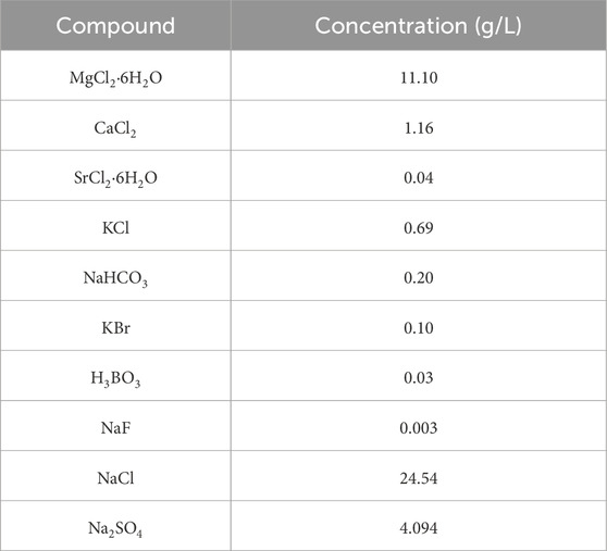
The fretting wear tests were performed on annealed TC4 alloy and TC4 alloy samples subjected to 240 min of surface mechanical attrition treatment (SMAT). The roughness (Ra) of TC4 alloy before and after surface mechanical treatment for 240 min is 366 and 1,133, respectively. The Vickers hardness of the material was evaluated before and after SMAT. At a depth of 60 μm from the treated surface, the average hardness, based on five measurements, increased from 364 for the untreated material to 437 after 240 min of SMAT. Similarly, at a depth of 160 μm, the average hardness increased from 360 in the untreated state to 376 after 240 min of SMAT. The original microstructure and chemical composition were shown in Figure 1 and Table 1. The sample size was 30 mm × 30 mm × 6 mm. The friction pair is Al2O3 ceramic ball (diameter: 5.953 mm). The solution environment used in the fretting wear test was artificial seawater environment. According to ASTM D1141-98 standard (Singh et al., 2020), the artificial seawater with chemical composition as shown in Table 2 was prepared, and its pH value was 8.2 ± 0.1 at room temperature.
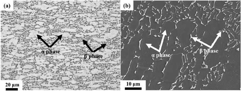
Figure 1. The microstructure of TC4 alloy under different microscopes. (A) Optical microscope, (B) Electron microscope.
The fretting wear tests in seawater were conducted using the Rtec multifunctional friction and wear tester (MFT-5000). A custom-made liquid pool was installed on the high-frequency reciprocating module to fix the fretting wear sample and accommodate the solution, as shown in Figure 2. The tester was capable of simultaneously recording three parameters: friction coefficient, amplitude and load during the fretting wear test. The parameters of fretting wear test were set as follows: loading force ranged from 2 to 10 N, fretting frequency was set at 10 Hz, amplitude was 150 μm, and 1 a total of 10,000 cycles were performed. To ensure the repeatability of the results, three experiments were conducted under each condition.
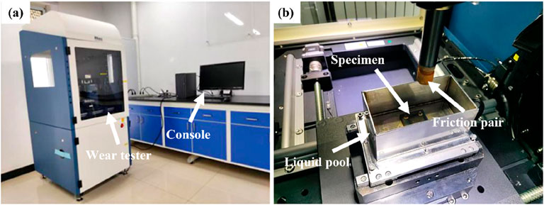
Figure 2. Equipment for fretting wear. (A) Rtec multifunctional friction and wear tester, (B) Fretting wear platform.
After the experiments, the specimens were cleaned ultrasonically in alcohol for 10 min to remove any residual debris. After drying, the worn surface morphology and cross-sectional morphology of the wear scars on the TC4 alloy plates were characterized by scanning electron microscope (SEM) equipped with an energy dispersive spectrometer (EDS) detector.
The wear volume and depth of the wear scars were quantified using a white light interferometer, enabling the subsequent calculation of the wear rate. Friction force and time data were obtained from the multifunctional friction and wear tester, from which the friction coefficient curve over time was derived to assess the wear resistance of the TC4 alloy before and after surface mechanical attrition treatment (SMAT). Based on these results, a comprehensive investigation was conducted on the wear behavior of the untreated and SMAT-treated TC4 alloy in artificial seawater under varying load conditions.
3 Results and discussion
3.1 Effect of load on friction coefficient (macro-level)
Figure 3A shows the friction coefficient curves of TC4 alloy after 240 min of SMAT treatment over the initial 40 cycles of fretting wear under loads of 2 N, 4 N, 6 N, 8 N, and 10 N. Figure 3B shows the friction coefficient curve over an extended 50,000-cycle fretting wear period under these loads. From Figure 3A, it is evident that the friction coefficient for all samples rises rapidly during the initial 3 to 4 cycles. This is followed by a slower increase in the friction coefficient over the subsequent 3 to 10 cycles, showing a fluctuating pattern of down-up oscillations. In Figure 3B, after approximately 10 cycles, the friction coefficient of each sample exhibits a gradual upward trend, stabilizing more slowly with increasing cycles. Additionally, it is noted that, within the first 10,000 cycles, the friction coefficient under all loads experiences an initial increase before reaching a relatively stable state after 10,000 cycles.
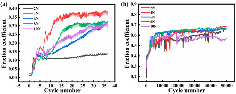
Figure 3. The friction coefficient curves of TC4 alloy after SMAT treatment for 240 min under different cycles of 2 N, 4 N, 6 N, 8 N and 10 N loads. (A) 40 cycles, (B) 50,000 cycles.
During the initial 5 cycles, the friction pair enters a running-in stage characterized by a low friction coefficient (Chen L. et al., 2024), with a maximum value below 0.2. This lower coefficient is attributed to the presence of an oxide film on the TC4 alloy surface, which initially provides a lubricating effect. However, as friction progresses, this oxide film begins to degrade, resulting in increased adhesion and plastic deformation between the contact surfaces, causing the friction coefficient to rise sharply. Between 3 and 10 cycles, the oxide film is fully worn away, exposing the TC4 alloy to direct contact with the grinding ball. This exposure enlarges the actual contact area, leading to a continued rise in friction coefficient, though at a slower rate than the initial stage. Around 10 to 10,000 cycles, a transition occurs from two-body to three-body contact. At this stage, wear debris accumulates between the contact surfaces, acting as a third body that provides lubrication (Zabihi et al., 2024), similar to tiny rolling elements. This accumulated debris moderates the friction coefficient, causing it to stabilize. However, due to the rate of debris formation exceeding its removal rate, localized increases in friction are observed, though overall, the friction coefficient continues a gradual climb from approximately 0.2 to over 0.5. Beyond 10,000 cycles, continuous particle exfoliation and oxidation of wear debris occur under fretting forces, creating a dynamic balance as the debris formation rate equals its removal rate. This results in minimal fluctuations in the friction coefficient, which stabilizes between 0.5 and 0.65.
From Figures 3A, B, it can be seen that during the fretting wear process of 50,000 cycles, the friction coefficient for the 2 N and 10 N loads remains relatively low, while the coefficients for other loads exhibit similar values. This suggests that, under the test conditions, there is no clear relationship between friction coefficient and applied load (Chen et al., 2002).
3.2 Effect of load on surface morphology (meso-level)
Figure 4 shows the two-dimensional wear surface profile of the original TC4 alloy and after SMAT treatment for 240 min after fretting wear for 50,000 cycles under 2 N, 4 N, 6 N, 8 N and 10 N loads. It can be seen from the figure that under the condition of 2N load [Figure 4 (a1) and (a2)], both the untreated and SMAT treatment samples exhibit an elliptical wear scar contour, indicating a gross slip fretting regime under these conditions. The wear scar width (along the fretting wear direction) and height (perpendicular to the wear direction) were measured from the edge distances of the wear scar. At a 4 N load [Figure 4 (b1) and (b2)], the width-to-height ratio of the wear scar decreases, and the SMAT-treated sample shows a smaller width-to-height ratio than the untreated sample, suggesting a more focused wear pattern post-treatment. As the load increases to 6 N [Figure 4 (c1) and (c2)], the width-to-height ratio of both wear scars further reduces, nearing a ratio of 1, indicating an evolution in wear shape towards more symmetric contours. When the load reaches 8N [Figure 4 (d1) and (d2)], the wear scar of the SMAT treatment sample achieves a nearly circular profile with a width-to-height ratio close to 1. Although the wear scar of the untreated sample also trends toward circularity, it remains slightly elliptical. Finally, under the 10 N load [Figure 4 (e1) and (e2)], the edge contours of the wear scars for both the untreated and SMAT treatment samples are approximately circular, signifying an advanced stage of wear symmetry and uniform contact area distribution at higher loads.
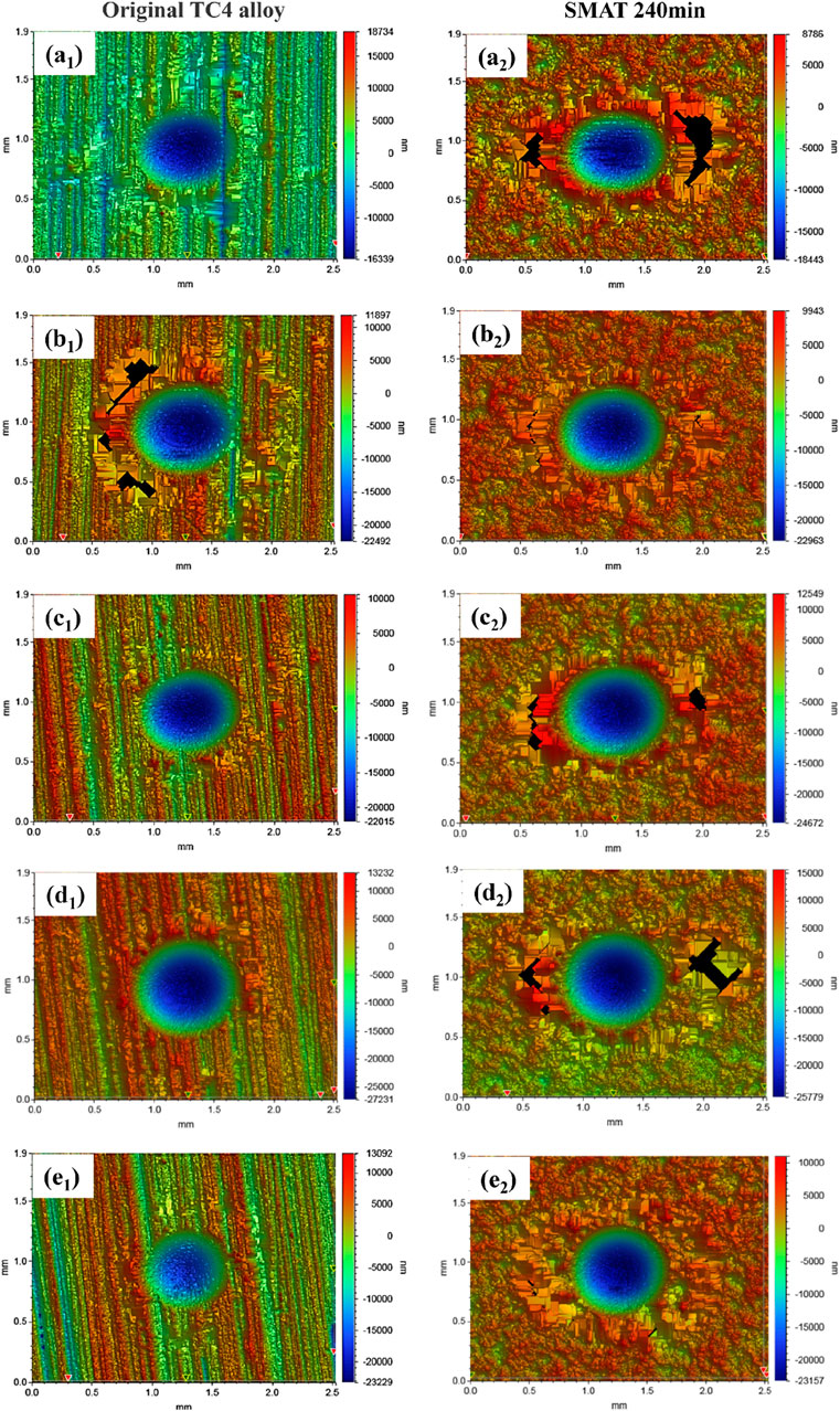
Figure 4. The two-dimensional wear surface profile of the original TA4 alloy and SMAT treatment for 240 treatment utes under different loads. (a1) and (a2) 2 N, (b1) and (b2) 4 N, (c1) and (c2) 6 N, (d1) and (d2) 8 N, (e1) and (e2) 10 N.
As the load increases from 2 N to 10 N, the wear scar morphology tends to be approximately circular whether it is before or after SMAT treatment, indicating that the wear mode of the sample gradually tends from gross slip regime (GSR) to partial slip regime (PSR) (Vingsbo and Söderberg, 1988; Garcin et al., 2015). Moreover, the sample after SMAT treatment can approach the partial slip regime faster with the increase of load. Under the same load, the wear scar of the sample after SMAT treatment is smaller than that of the sample without SMAT treatment, which reflects that SMAT has a certain improvement effect on the wear resistance of TC4 alloy surface.
Figures 5, 6 show the SEM and EDS images of the wear scars of TC4 alloy without SMAT treatment and after SMAT treatment for 240 min under different loads, respectively. From the SEM images, it can be observed that the wear scars on the surface of the material are approximately elliptical or circular whether before or after SMAT treatment, and the shape of the wear scars tends to be circular with the increase of the load. Notably, a ring of wear debris can be observed protruding from the matrix plane around the wear scars. This accumulation of wear debris occurs due to the material removal during the wear process, where debris is either expelled or squeezed out from the grinding pit as a result of the relative motion between the ball and the plate. The presence of this wear debris may influence the friction and wear behavior by providing a lubricating effect (Blau, 1981), potentially contributing to a reduction in the overall wear rate.
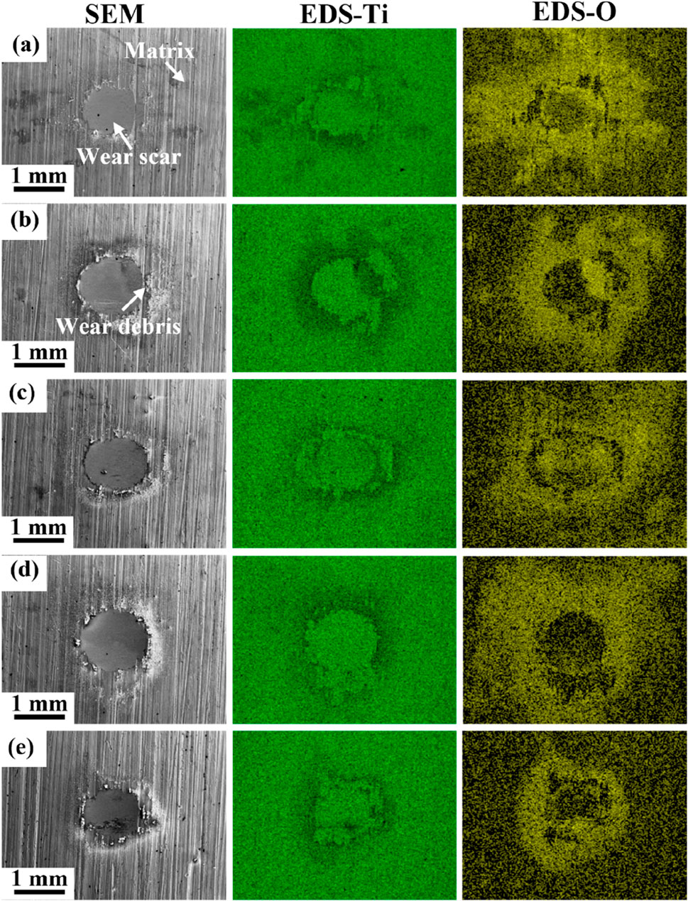
Figure 5. The SEM and EDS images of the wear morphology of the original TC4 alloy under different loads. (A) 2 N, (B) 4 N, (C) 6 N, (D) 8 N, (E) 10 N.
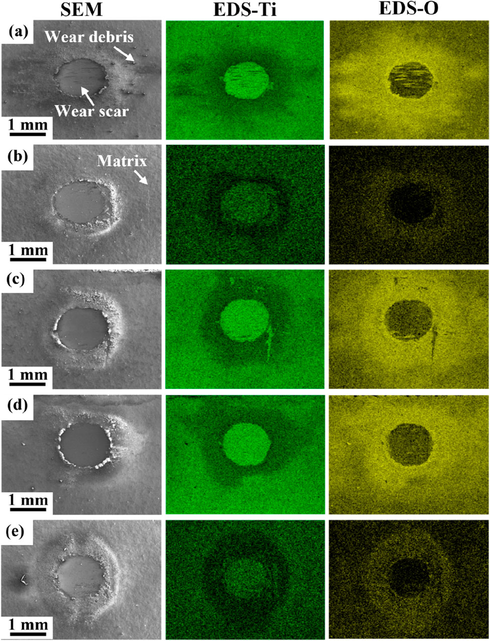
Figure 6. The SEM and EDS images of the wear morphology of the SMAT treatment for 240 min under different loads. (A) 2 N, (B) 4 N, (C) 6 N, (D) 8 N, (E) 10 N.
It can be found from the EDS images that the content of Ti in the wear scar is higher than in both the surrounding wear debris and the matrix. This increased Ti concentration is attributed to the presence of an oxide film on the substrate, which has been removed from the wear scar area by the grinding ball during the wear process. The overall O in the wear scar is lower compared to the surrounding region, while the O concentration within the grooves of the wear scar area is elevated. This suggests that the majority of the wear scar is less influenced by oxidation compared to mechanical actions during wear. Consequently, oxidative wear does not appear to be the primary wear mechanism; however, oxidation is more pronounced in the grooves. In the wear debris area, the content of O is significantly higher, while the Ti content is relatively low. This indicates that the wear debris undergoes a complete reaction with oxygen as it detaches from the matrix, potentially resulting in the formation of TiOx wear debris products (Shi et al., 2023).
Figure 7 shows the wear morphology SEM images of the original TA4 alloy and SMAT treatment for 240 min under different loads. At a load of 2N [Figure 7 (a1) and (a2)], the groove is basically evenly distributed on the whole wear scar surface, with an abundance of white wear debris accumulating near these grooves. This observation suggests that abrasive wear predominates at this stage, as abrasive particles scratch the substrate, resulting in the formation of grooves and the accumulation of wear debris around them. With the increase of the load, the main area of the grooves gradually changes from the whole wear scar to its edges. The central area of the wear scar shows a reduction in the depth and presence of grooves, leading to a smoother grinding surface. Consequently, the number of abrasive particles also decreases. This trend is consistent with the findings in Figure 4, which indicate that at a load of 2 N, the fretting wear is carried out in a gross slip regime. However, as the load increases, the fretting wear changes to the partial slip regime. At the edges of the wear scar, relative motion occurs between the grinding materials, resulting in the formation of numerous grooves due to abrasive wear (Rajendhran et al., 2023). In contrast, in the central region of the wear scar, the increase in load leads to a decrease in groove depth, significantly reducing the extent of abrasive wear. Here, adhesive wear emerges as the primary mode of wear, highlighting the transition in wear mechanisms as load conditions change.
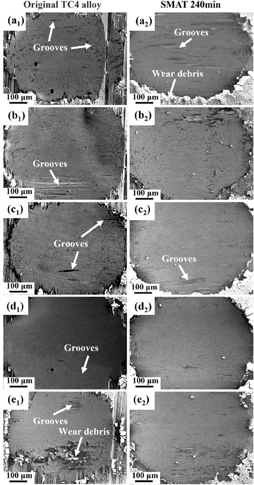
Figure 7. The wear morphology SEM images of the original TA4 alloy and SMAT treatment for 240 min under different loads. (a1) and (a2) 2 N, (b1) and (b2) 4 N, (c1) and (c2) 6 N, (d1) and (d2) 8 N, (e1) and (e2) 10 N.
3.3 Wear depth and wear volume
According to Figure 8, the wear scar exhibits an approximately hemispherical crater shape. The part that is absent below the matrix corresponds to the wear volume measured during the tests. For the measurement of wear depth, as shown in Figure 8, it is represented by the height difference ΔZ between the height R line at the intersection with the wear scar and the height M line at the intersection with the matrix profile. The wear depth is recorded from the center of the wear scar to determine its maximum depth. All wear depths referenced in this paper pertain to this maximum wear depth. The wear rate is calculated by formula (Arnaud et al., 2017):
Where V is the wear volume, t is the wear time.
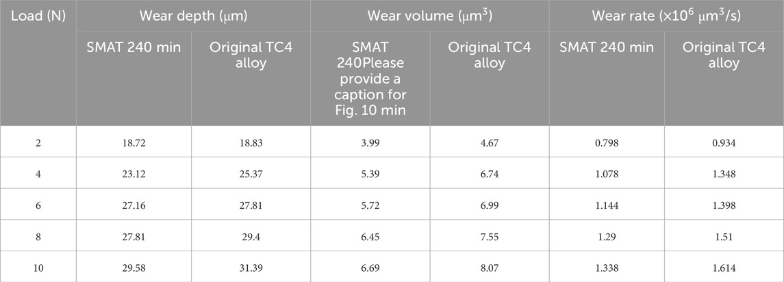
Table 3 shows the wear depth, wear volume and wear rate (Calculated by Equation 1) for both the original TC4 alloy sample and the sample subjected to SMAT treatment for 240 min across various loads. At a load of 2 N, the wear depth is 18.83 μm, and the wear volume is 4.67 × 10 μm3. Notably, these values are the lowest observed during the fretting wear tests across all loads, with the wear time remaining consistent, indicating that the wear rate and wear volume exhibit similar trends. With the increase of load, both the wear depth and wear volume also demonstrate a corresponding increase (Wei et al., 2024). When the load reaches 10 N, the maximum wear depth is 31.39 μm, and the wear volume is 7.55 × 10 μm3. The trends of wear depth and wear volume in relation to load are illustrated in Figures 9A, B.
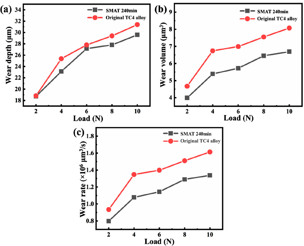
Figure 9. (A) The change curve of wear depth with load before and after SMAT. (B) The change curve of wear volume with load before and after SMAT. (C) The change curve of wear rate with load before and after SMAT.
Figure 9A shows the relationship between wear depth and load. The diagram reveals that at a load of 2 N, the wear depth difference before and after SMAT treatment is minimal, with both measurements falling within the range of 18 and 19 μm. When the load increases to 4 N, there is a significant increase in wear depth for both samples. Specifically, the wear depth before SMAT treatment reaches 25.37 μm, and the wear depth after SMAT treatment reaches 23.12 μm, indicating a notable reduction in wear depth due to SMAT treatment. When the load increases to 6 N, the wear depth before and after SMAT treatment further increases. The wear depth before SMAT treatment reaches 27.81 μm, and the wear depth after SMAT treatment reaches 27.16 μm. The wear depth after SMAT treatment is still less than the wear depth before SMAT treatment. When the load increases to 8 N, the wear depth before and after SMAT treatment still keeps increasing. The wear depth before SMAT treatment reaches 29.4 μm, and the wear depth after SMAT treatment reaches 27.81 μm. When the load increases to 10 N, the wear depth of both reaches the maximum. Overall, the curve indicates that the wear depths for both samples at 2 N are similar, and that wear depth gradually increases with increasing load. Throughout the entire testing process, the wear depth of the untreated sample consistently exceeds that of the SMAT treatment sample at equivalent loads, demonstrating the effectiveness of SMAT treatment in enhancing wear resistance. Figure 9B shows the relationship between wear volume and load. It can be seen from the diagram that when the load is 2 N, the wear volume before and after SMAT treatment is very small (Tang et al., 2024). The wear volume before SMAT treatment reaches 4.67 μm3, and the wear volume after SMAT treatment reaches 3.99 μm3. When the load increases to 4 N, the wear volume before and after SMAT treatment increases greatly. The wear volume before SMAT treatment reaches 6.74 μm3, and the wear volume after SMAT treatment reaches 5.39 μm3, which is significantly smaller than the wear volume before SMAT treatment. When the load increases to 6 N, the wear volume before and after SMAT treatment increases further. The wear volume before SMAT treatment reaches 5.99 μm3, and the wear volume after SMAT treatment reaches 5.74 μm3. The wear volume after SMAT treatment is still smaller than the wear volume before SMAT treatment. When the load increases to 8 N, the wear volume before and after SMAT treatment still maintains an increasing trend. The wear volume before SMAT treatment reaches 7.55 μm3, and the wear volume after SMAT treatment reaches 6.45 μm3. When the load increases to 10 N, the wear volume of both reaches the maximum. From the overall trend of the curve in the figure, as the load increases, the wear volume gradually increases. In the process of 2–4 N, the wear volume increases rapidly; in the process of 4–10 N, the wear volume growth is relatively flat, which is due to the wear mode from gross slip regime to partial slip regime, and the wear volume of partial slip regime is less than that of gross slip regime (Pinto et al., 2020; Xin et al., 2017). In the whole process, the wear volume before SMAT treatment is always larger than that after SMAT treatment under the same load. Figure 9C shows the relationship between wear rate and load. From the diagram, it can be found that the wear rate gradually increases with the increase of load. In the process of 2 N–4 N, the wear rate increases rapidly; in the process of 4 N–10 N, the wear rate growth is relatively flat. During the whole process, the wear rate after SMAT treatment is always lower than that before SMAT treatment under the same load. The trend of the figure is consistent with the trend of wear volume changing with load in Figure 9B, because the wear rate is the ratio of wear volume to wear time. In this paper, the wear time under different loads before and after SMAT treatment is consistent, so the wear rate and wear volume trend are consistent (Shuai et al., 2024).
Overall, the improvement in fretting wear performance by SMAT is primarily related to its effect on the material’s surface microstructure. SMAT treatment applies high-frequency vibration and impact force to the material’s surface, causing plastic deformation in the surface layer and forming fine nanocrystalline (NG) structures (Yang et al., 2024). Nanocrystals possess higher hardness and better wear resistance, effectively reducing wear during friction. This nanocrystalline layer exhibits a gradient structure between the surface and the matrix, which strengthens the bond between the surface layer and the matrix, preventing delamination or separation due to external forces, thus enhancing wear resistance (Han et al., 2024). SMAT treatment also introduces compressive residual stress in the surface and subsurface layers, which helps inhibit the propagation of microcracks and reduces the likelihood of fatigue failure during fretting wear (Zhou et al., 2022). Experimental results show that the wear depth and wear volume of SMAT-treated samples are consistently smaller than those of untreated samples under various loads, indicating that the introduction of surface compressive stress effectively enhances fatigue resistance.
4 Conclusion
In this study, the fretting wear scars of the matrix without SMAT treatment and the samples treatment by SMAT for 240 min under 2 N, 4 N, 6 N, 8 N and 10 N conditions were characterized by SEM, EDS and white light interferometer. The variation trend of friction coefficient, wear depth, wear volume and wear rate with load was studied. The conclusions are as follows:
1. In the artificial seawater environment, the fretting wear test was carried out with the test parameters of frequency of 10 Hz, amplitude of 150 μm, cycle number of 50,000 and different loads. For the sample treatment by SMAT for 240 min, the friction coefficient does not change much under different load test conditions, indicating that the friction coefficient is not significantly affected by the load.
2. With the increase of load, the fretting wear regime of the original TC4 alloy sample and the sample treatment by SMAT for 240 min changed from gross slip regime to partial slip regime. When the load is 2 N, both of them are in a gross slip regime; when the load reaches 10 N, the two are approximately in a partial slip regime.
3. With the increase of load, the wear depth, wear volume and wear rate of the original TC4 alloy sample and the sample treatment by SMAT for 240 min increased after fretting wear. Moreover, under the same load conditions, the wear volume of the sample treatment with SMAT for 240 min is smaller than that of the sample without SMAT treatment. It can be seen that SMAT treatment improves the wear resistance of TC4 alloy under different loads.
Data availability statement
The original contributions presented in the study are included in the article/supplementary material, further inquiries can be directed to the corresponding authors.
Author contributions
ZL: Funding acquisition, Investigation, Supervision, Writing–original draft, Writing–review and editing. FX: Funding acquisition, Supervision, Writing–review and editing. XL: Funding acquisition, Supervision, Writing–review and editing. SY: Investigation, Supervision, Writing–review and editing. BG: Investigation, Methodology, Writing–original draft. XZ: Investigation, Supervision, Writing–original draft, Writing–review and editing. LX: Funding acquisition, Investigation, Methodology, Supervision, Writing–review and editing.
Funding
The author(s) declare financial support was received for the research, authorship, and/or publication of this article. We are grateful for the financial support of the Interdisciplinary Research Project of Peking University Third Hospital (Grant No. BYSYJCZH2024002).
Conflict of interest
The authors declare that the research was conducted in the absence of any commercial or financial relationships that could be construed as a potential conflict of interest.
Publisher’s note
All claims expressed in this article are solely those of the authors and do not necessarily represent those of their affiliated organizations, or those of the publisher, the editors and the reviewers. Any product that may be evaluated in this article, or claim that may be made by its manufacturer, is not guaranteed or endorsed by the publisher.
References
Arnaud, P., Fouvry, S., and Garcin, S. (2017). Wear rate impact on Ti-6Al-4V fretting crack risk: experimental and numerical comparison between cylinder/plane and punch/plane contact geometries. Tribol. Int. 108, 32–47. doi:10.1016/j.triboint.2016.11.023
Blau, P. J. (1981). Mechanisms for transitional friction and wear behavior of sliding metals. Wear 72 (1), 55–66. doi:10.1016/0043-1648(81)90283-0
Chen, D., Zhang, P., Deng, Q., Deng, M., Yue, Z., Cai, Z., et al. (2024). Comparative investigation on the fretting and sliding wear properties of TC4 against GCr15 under different temperatures. Tribol. Int. 199, 109980. doi:10.1016/j.triboint.2024.109980
Chen, J., and Zhang, Q. (2016). Effect of electrochemical state on corrosion–wear behaviors of TC4 alloy in artificial seawater. Trans. Nonferrous Metals Soc. China 26 (4), 1011–1018. doi:10.1016/s1003-6326(16)64164-x
Chen, L., Lan, Y., Cheng, Y., Zeng, J., Ma, Y., Yu, S., et al. (2024). Friction behavior and wear mechanism of laser cladded FeNiCr-WC composite coatings in comparison with different friction pairs. J. Mater. Res. Technol. 31, 1956–1973. doi:10.1016/j.jmrt.2024.06.206
Chen, M., Kato, K., and Adachi, K. (2002). The comparisons of sliding speed and normal load effect on friction coefficients of self-mated Si3N4 and SiC under water lubrication. Tribol. Int. 35 (3), 129–135. doi:10.1016/s0301-679x(01)00105-0
Fayeulle, S., Blanchard, P., and Vincent, L. (1993). Fretting behavior of titanium alloys. Tribol. Trans. 36 (2), 267–275. doi:10.1080/10402009308983158
Feng, J., Wang, J., Yang, K., and Rong, J. (2022). Microstructure and performance of YTaO4 coating deposited by atmospheric plasma spraying on TC4 titanium alloy surface. Surf. Coatings Technol. 431, 128004. doi:10.1016/j.surfcoat.2021.128004
Fu, Y., Loh, N. L., Batchelor, A. W., Liu, D., Xiaodong, Z., He, J., et al. (1998). Improvement in fretting wear and fatigue resistance of Ti–6Al–4V by application of several surface treatments and coatings. Surf. Coatings Technol. 106 (2), 193–197. doi:10.1016/s0257-8972(98)00528-3
Fu, Y., Wei, J., and Batchelor, A. W. (2000). Some considerations on the mitigation of fretting damage by the application of surface-modification technologies. J. Mater. Process. Technol. 99 (1), 231–245. doi:10.1016/s0924-0136(99)00429-x
Garcin, S., Fouvry, S., and Heredia, S. (2015). A FEM fretting map modeling: effect of surface wear on crack nucleation. Wear 330-331, 145–159. doi:10.1016/j.wear.2015.01.013
Han, Z., Ma, Z., Shen, G., Zhang, W., Li, J., Li, Y., et al. (2024). An additively manufactured high-entropy alloy with superior wear resistance by nanoprecipitation and high density dislocations. Tribol. Int. 199, 109993. doi:10.1016/j.triboint.2024.109993
Kang, L., Mi, X., Zhang, X., Xin, L., Lu, Y., and Shoji, T. (2023). Detail characterization on the microstructure evolution of nickel-base alloy 600MA via surface mechanical attrition treatment. Mater. Charact. 195, 112498. doi:10.1016/j.matchar.2022.112498
Kanou, S., Nishikawa, M., and Soyama, H. (2013). Analysis of the formation of plastic deformation layer on the surface of polycrystalline metals subjected to a micro-size high-rate shot impact. Int. J. Mech. Sci. 75, 316–323. doi:10.1016/j.ijmecsci.2013.07.014
Ke Lu, J. L. (1999) Surface nanocrystallization (SNC) of metallic materials-presentation of the concept behind a new approach, 15, 193–197.
Lu, K., and Lu, J. (2004). Nanostructured surface layer on metallic materials induced by surface mechanical attrition treatment. Mater. Sci. Eng. A 375-377, 38–45. doi:10.1016/j.msea.2003.10.261
Mountford, J. A. (2002). Titanium - properties, advantages and applications solving the corrosion problems in marine service. CORROSION.
Najafizadeh, M., Yazdi, S., Bozorg, M., Ghasempour-Mouziraji, M., Hosseinzadeh, M., Zarrabian, M., et al. (2024). Classification and applications of titanium and its alloys: a review. J. Alloys Compd. Commun. 3, 100019. doi:10.1016/j.jacomc.2024.100019
Oryshchenko, A. S., Gorynin, I. V., Leonov, V. P., Kudryavtsev, A. S., Mikhailov, V. I., and Chudakov, E. V. (2015). Marine titanium alloys: present and future. Inorg. Mater. Appl. Res. 6 (6), 571–579. doi:10.1134/s2075113315060106
Pinto, A. L., Cardoso, R. A., Talemi, R., and Araújo, J. A. (2020). Fretting fatigue under variable amplitude loading considering partial and gross slip regimes: numerical analysis. Tribol. Int. 146, 106199. doi:10.1016/j.triboint.2020.106199
Qin, X., Yang, H., Zhao, Y., Wan, S., Zhao, X., Yu, T., et al. (2024). Investigation of the microstructural characteristics of laser-cladded Ti6Al4V titanium alloy and its corrosion behavior in simulated body fluid. Mater. Today Commun. 41, 110780. doi:10.1016/j.mtcomm.2024.110780
Rajendhran, N., Pondicherry, K., Huang, S., Vleugels, J., and De Baets, P. (2023). Influence of abrasive characteristics on the wear micro-mechanisms of NbC and WC cermets during three-body abrasion. Wear 530-531, 205007. doi:10.1016/j.wear.2023.205007
Shi, P., Sun, H., Yi, G., Wang, W., Wan, S., Yu, Y., et al. (2023). Tribological behavior and mechanical properties of thermal sprayed TiO2–ZnO and TiOx ceramic coatings. Ceram. Int. 49, 18662–18670. doi:10.1016/j.ceramint.2023.02.243
Shuai, C., Xie, J., Yu, Z., Yang, Y., and Wang, C. (2024). Enhanced wear resistance of in-situ nanoscale TiC reinforced Ti composites fabricated by additive manufacturing. Vacuum 230, 113704. doi:10.1016/j.vacuum.2024.113704
Singh, A., Dayu, X., Ituen, E., Ansari, K., Quraishi, M. A., Kaya, S., et al. (2020). Tobacco extracted from the discarded cigarettes as an inhibitor of copper and zinc corrosion in an ASTM standard D1141-98(2013) artificial seawater solution. J. Mater. Res. Technol. 9 (3), 5161–5173. doi:10.1016/j.jmrt.2020.03.033
Sun, Q., Hu, T., Fan, H., Zhang, Y., and Hu, L. (2016). Thermal oxidation behavior and tribological properties of textured TC4 surface: influence of thermal oxidation temperature and time. Tribol. Int. 94, 479–489. doi:10.1016/j.triboint.2015.10.013
Tang, G., Ou, Z., Liu, F., Li, T., Su, F., Zheng, J., et al. (2024). Enhancing wear resistance of aluminum alloy by fabricating a Ti-Al modified layer via surface mechanical attrition treatment. Tribol. Int. 193, 109462. doi:10.1016/j.triboint.2024.109462
Vingsbo, O., and Söderberg, S. (1988). On fretting maps. Wear 126 (2), 131–147. doi:10.1016/0043-1648(88)90134-2
Vlcak, P., Fojt, J., Weiss, Z., Kopeček, J., and Perina, V. (2019). The effect of nitrogen saturation on the corrosion behaviour of Ti-35Nb-7Zr-5Ta beta titanium alloy nitrided by ion implantation. Surf. Coatings Technol. 358, 144–152. doi:10.1016/j.surfcoat.2018.11.004
Wang, J., Duan, D., Xue, W., Gao, S., and Li, S. (2020). Ti-6Al-4V fretting wear and a quantitative indicator for fretting regime evaluation. Proc. Institution Mech. Eng. Part J J. Eng. Tribol. 235 (2), 423–433. doi:10.1177/1350650120933115
Wang, K., Tao, N. R., Liu, G., Lu, J., and Lu, K. (2006). Plastic strain-induced grain refinement at the nanometer scale in copper. Acta Mater. 54 (19), 5281–5291. doi:10.1016/j.actamat.2006.07.013
Wei, W., Ke, J., Liu, Z., Chen, Y., Liu, G., and Hua, L. (2024). The influences of normal load and displacement amplitude on fretting wear behavior of M50 bearing steel. Tribol. Int. 199, 109944. doi:10.1016/j.triboint.2024.109944
Wen, A. L., Wang, S. W., Ren, R. M., and Yan, X. X. (2010). Effect of combined shot peening process for surface nanocrystallization method on fatigue strength of TC4. Adv. Mater. Res. 97-101, 2217–2220. doi:10.4028/www.scientific.net/amr.97-101.2217
Wood, R. J. K. (2017). Marine wear and tribocorrosion. Wear 376-377, 893–910. doi:10.1016/j.wear.2017.01.076
Xin, L., Yang, B. B., Li, J., Lu, Y. H., and Shoji, T. (2017). Wear damage of Alloy 690TT in partial and gross slip fretting regimes at high temperature. Wear 390-391, 71–79. doi:10.1016/j.wear.2017.07.006
Yan, S., Song, G.-L., Li, Z., Wang, H., Zheng, D., Cao, F., et al. (2018). A state-of-the-art review on passivation and biofouling of Ti and its alloys in marine environments. J. Mater. Sci. and Technol. 34 (3), 421–435. doi:10.1016/j.jmst.2017.11.021
Yang, H., Zhang, Z., Shu, J., and Han, Y. (2024). Gradient nanostructure, enhanced surface integrity and fatigue resistance of Ti-6Al-7Nb alloy processed by surface mechanical attrition treatment. J. Mater. Sci. and Technol. 188, 252–269. doi:10.1016/j.jmst.2023.12.011
Zabihi, A., Juoksukangas, J., Hintikka, J., Salminen, T., Mäntylä, A., Vaara, J., et al. (2024). Influence of displacement amplitude on fretting-induced friction and wear of steel in oil-lubricated contact. Tribol. Int. 193, 109451. doi:10.1016/j.triboint.2024.109451
Keywords: TC4 alloy, fretting wear, load, SMAT, fretting regime
Citation: Liu Z, Xu F, Luan X, Yu S, Guo B, Zhang X and Xin L (2024) The effect of load on the fretting wear behavior of TC4 alloy treated by SMAT in artificial seawater. Front. Mater. 11:1520286. doi: 10.3389/fmats.2024.1520286
Received: 31 October 2024; Accepted: 09 December 2024;
Published: 24 December 2024.
Edited by:
Xu-Sheng Yang, Hong Kong Polytechnic University, Hong Kong SAR, ChinaReviewed by:
Pavlo Maruschak, Ternopil Ivan Pului National Technical University, UkraineWeichen Xu, Chinese Academy of Sciences (CAS), China
Copyright © 2024 Liu, Xu, Luan, Yu, Guo, Zhang and Xin. This is an open-access article distributed under the terms of the Creative Commons Attribution License (CC BY). The use, distribution or reproduction in other forums is permitted, provided the original author(s) and the copyright owner(s) are credited and that the original publication in this journal is cited, in accordance with accepted academic practice. No use, distribution or reproduction is permitted which does not comply with these terms.
*Correspondence: Zhenlin Liu, MTI2MzE4ODQ2MkBiam11LmVkdS5jbg==; Xiaofeng Zhang, emhhbmd4aWFvZmVuZ0B1c3RiLmVkdS5jbg==; Long Xin, bG9uZ194aW5AdXN0Yi5lZHUuY24=
 Zhenlin Liu1*
 Long Xin
