- 1College of Civil Engineering, Tongji University, Shanghai, China
- 2Department of Civil Engineering, University of Engineering and Technology, Peshawar, Pakistan
- 3Omicron AEC Inc., Vancouver, BC, Canada
- 4Institute of Energy Infrastructure, Universiti Tenaga Nasional, Kajang, Malaysia
- 5Department of Civil Engineering, University of Engineering and Technology Peshawar (Bannu Campus), Bannu, Pakistan
- 6Peter the Great St. Petersburg Polytechnic University, St. Petersburg, Russia
Composite construction materials are extensively employed and have proven to be more effective than their individual components, such as steel and concrete. This is because composites combine the strengths of different materials, resulting in enhanced properties such as increased strength-to-weight ratios, better durability, and improved thermal efficiency. However, despite the strong structural properties and energy-saving benefits of reinforced concrete sandwich panels, their use is restricted in many rural regions of developing nations like Pakistan, largely because of the economic limitations faced by the communities. Therefore, this study introduces cost-effective structural mud insulated panels (SMIPs) that utilize mud wythes and evaluates their mechanical performance. These panels consist of a lightweight Expanded Polystyrene (EPS) foam core, sandwiched between two galvanized steel-reinforced mud layers. The study includes flexural, compression, diagonal tension, and water absorption tests. Flexural tests revealed that the panels have substantial load-bearing capacity under bending forces. Whereas, Compression tests showed that the panels possess adequate strength and stiffness to support moderate structural loads. Additionally, Diagonal tension tests confirmed the panels’ ability to resist significant in-plane loads. Water absorption tests also indicated that the panels demonstrated adequate moisture resistance, staying within the acceptable limit of 15%. These findings highlight the mechanical and hydric properties of SMIPs, underscoring their potential in sustainable construction, especially in economically constrained regions.
1 Introduction
Rapid declination of natural resources for producing fine and coarse aggregates and increase in global warming have required research on effective use of building materials and sustainable construction (CityChangers, 2024). Solely depending on the primary material like cement or steel, it is more effective to use sustainable composite materials in building construction. Composite materials, including sandwich panels, are made by layering different materials like mud plaster, form and steel mesh to improve strength, insulation, and cost-efficiency (Abdelghani, 2003). In most cases, a reduction in the self-weight of the member is also a key factor (Fernando et al., 2017). In the last few decades, reinforced concrete sandwich panels (RCSP) have been used to construct structural members such as walls, slabs, and roofs. RCSP typically consists of an expanded polystyrene (EPS) core, wythes, and steel mesh, with the steel mesh welded across the EPS thickness to transfer shear stresses and ensure composite behavior (Benayoune et al., 2001; Gara et al., 2012). Shotcrete is applied to both sides of the core, forming the concrete wythes, making up the composite structure. EPS, constituting about 50% of the RCSP volume, is lightweight and often reused from packaging, contributing to environmental sustainability (Fernando et al., 2017; Kan and Demirboğa, 2009). Moreover, different researchers have explored the behavior of RCSP with different loading, configuration and materials (Benayoune et al., 2001; Benayoune et al., 2007; Benayoune et al., 2008; Benayoune et al., 2006; Bush and Stine, 1994; Bush and Wu, 1998; Carbonari et al., 2012; Bush and Stine, 1994). Additionally, research has been conducted on new sustainable construction materials, such as foamed concrete and fiber concrete, for use as a wythe in RCSP (Fernando et al., 2017; Amran et al., 2016).
Research on the flexural performance of concrete sandwich panels has shown that those with cement fiber wythes exhibit higher failure stress than those without, although both types fail in a brittle manner (Fernando et al., 2017). In another study, panels with foamed concrete wythes experienced increased crack width at mid-span, which led to failure at the ultimate load (Amran et al., 2016). In one-way precast concrete sandwich panels (PCSP), flexure cracks appeared along the bottom wythe. All panels eventually failed due to steel failure and crack propagation in the tension zone. The experimental analysis of reinforced mud sandwich panels (RMSPs) shows significantly higher deflections than those of cement-stabilized soil block masonry (Tennant et al., 2016; Liang et al., 2024). The load-deflection profiles of RMSPs were linear at first, becoming nonlinear as larger cracks formed, consistent with prior studies (Sarwar et al., 2024; Mohamad et al., 2014; Ahmad and Singh, 2021a). The maximum deflection occurred at the mid-span, the most critical area (Sarwar et al., 2024; Benayoune et al., 2001; Bishnoi et al., 2021; Mohamad et al., 2014; Tennant et al., 2016). Despite substantial midpoint deformations up to 108 mm, the panels maintained structural integrity, demonstrating significant deformation capacity (Benayoune et al., 2008; Sarwar et al., 2024).
There is research in which six precast foamed concrete sandwich panels PFCSPs with varying slenderness ratios tested. Initial cracking was observed at 33%–82% of the ultimate load. The ultimate bearing capacity decreased as the slenderness ratio increased (Benayoune et al., 2007; Mugahed Amran et al., 2016). In one of the study buckling was identified as the primary failure mode (Mohamad et al., 2017) while another study showed that the capping beams ensured the uniform load transfer and prevented local crushing and also the buckling failure of the specimen (Ahmad and Singh, 2021b). Test results revealed the formation of vertical cracks along the specimen heights. Also observations included vertical and transverse splitting of the wythes, concrete crushing, and spalling (Ahmad and Singh, 2021b). Concrete sandwich panels (CSPs) can replace conventional load-bearing brick masonry walls and can reduce the structure’s dead weight by nearly 50% (Daniel Ronald Joseph et al., 2023). So, these panels are suitable for load-bearing applications in multi-stored buildings, especially on low bearing capacity ground (Mugahed Amran et al., 2016). Samples were tested in diagonal compression, two specimens experienced premature failure of one concrete layer due to slight axial load eccentricity. All specimens exhibited high first cracking loads, but only one specimen achieved diagonal tensile failure as it was reinforced with transversal stiffening walls, while others showed concrete crushing at the load application point (Gara et al., 2012). It was observed that specimens predominantly failed due to the formation of tensile cracks along the vertical diagonal. The ultimate average shear strength of a specimen with a total thickness of 180 mm was found to be 4.67 MPa.
One of the primary aims of incorporating composite materials, such as sandwich panels, in the construction industry is to promote sustainable construction. It is well known that carbon dioxide (CO2) is a significant contributor to global warming, with human activities, including cement production and the burning of various materials, being the primary sources of CO2 emissions. For every 1,000 kg of cement produced, approximately 866 kg of CO2 is generated (Bistline and Rai, 2010; Celik et al., 2015; Ahmed et al., 2023; Liu et al., 2024). The substantial growth of the global economy and population is anticipated to lead to an enormous demand for energy, thereby increasing CO2 concentrations in the atmosphere (Solomon et al., 2007; Planas et al., 2013; Zhao et al., 2024; Zhao et al., 2024). The construction industry is a leading contributor to CO2 emissions, accounting for an estimated 7% of the total greenhouse gases released into the atmosphere (Benhelal et al., 2013). Numerous studies have been conducted on alternative cementitious materials to investigate their properties and applications, aiming to reduce the environmental impact of construction (Alam et al., 2015) (Agarwal and Taylor, 1982) (Danso et al., 2015) (Dai et al., 2024). Incorporating these innovative materials is a crucial step toward more sustainable building practices and reducing the carbon footprint of the construction industry.
Mud is a fundamental material in both traditional and modern construction, renowned for its sustainability due to its widespread availability, cost-effectiveness, and minimal environmental impact. Earth or mud has been a prevalent construction material for over 9,000 years (Minke, 2006). Approximately 1.7 billion people worldwide reside in earthen houses (Benhelal et al., 2013), which are considered environmental friendly and affordable as compared to houses built with other material for a multitude of reasons, e. g., earthen houses are known to improve the indoor air quality and thermal comfort (Cascione et al., 2019), they consume minimal energy for material production and the transportation costs are reduced due to local resource utilization (Morel et al., 2001). To achieve desire properties from the mud, it is modified by adding stabilizer. While cement is an effective modern stabilizer, as significant decrease in water absorption is observed in the case of cement-stabilized bricks, it also enhances the tensile and compressive strength of mud (Alam et al., 2015; Prakash and Raj, 2016; Ngowi, 1997; Walker and Stace, 1997). Its use should be balanced with environmental considerations due to its significant CO2 emissions.
Previous studies on reinforced sandwich panels have mainly addressed their parametric and reinforcement properties, boundary conditions, and loading conditions, with a consistent focus on panels with concrete wythes (Abdelghani, 2003; Benayoune et al., 2001; Benayoune et al., 2007; Benayoune et al., 2008; Bush and Stine, 1994; Bush and Wu, 1998; Carbonari et al., 2012; Amran et al., 2016; Mohamad et al., 2014; Ahmad and Singh, 2021a; Bishnoi et al., 2021; Daniel Ronald Joseph et al., 2018; Daniel Ronald Joseph et al., 2017). There are very few research articles exist on the assessment of the flexure performance of reinforced mud sandwich panel (Sarwar et al., 2024). This approach, which replaces traditional materials like cement concrete with stabilized mud, offers an eco-friendly alternative for casting structural components and non-load-bearing or boundary walls. In developing countries, structural mud insulated panels (SMIPs) could serve as a composite material that contributes to the United Nations Sustainable Development Goals (SDGs) by lowering carbon emissions. The primary aim of this study is to investigate the flexural, compressive, shear strength and water absorption capacity of SMIPs under different loading condition to evaluate various structural aspects, including load-bearing capacities, deformation, stiffness, crack patterns, failure modes and water absorption capacity. Flexural tests recorded a maximum load of 6 kN with a displacement of 119.83 mm, while compression tests revealed an average stress of 0.817 MPa and a Young’s Modulus of 55.33 MPa. Additionally, diagonal tension tests demonstrated a maximum load capacity of 29.5 kN and a shear strength of 0.170 MPa. Furthermore, water absorption tests showed an average rate of 13.88%, which is within the acceptable limit. Together, these findings provide valuable insights into the mechanical and hydric properties of SMIPs, suggesting their potential for sustainable construction, particularly in regions where economic considerations are crucial.
2 Experimental setup
The SMIP in this study was constructed from reinforced sandwich panels (RSP) with mud wythes. The RSP consisted of expanded polystyrene (EPS) with a density of 21.62 kg/m3 and a thickness of 102 mm and 51 mm as the core material, enclosed within a steel mesh. The steel mesh reinforcement comprised 2 mm diameter galvanized steel wires, placed at 50.8 mm center-to-center along the width and length of the panel, and connected through welding. Additionally, the galvanized steel wires, forming a 67.5° angle with the horizontal plane, connected the meshes by welding across the thickness of the EPS, acting as shear connectors, as shown in Figure 1A. The dimensions of each flexure panel were 3,048 mm × 1,219 mm × 152.4 mm (length, width, and thickness, respectively) (Figure 1B) and the dimensions of compression, diagonal tension and water absorption panels were 609.6 mm × 457 mm × 203 mm, 1,219 mm × 1,219 mm × 203 mm and 609.6 mm × 305 mm × 203 mm respectively. The panels used in this research were provided by Norwest (PVT) LTD., Islamabad, Pakistan.
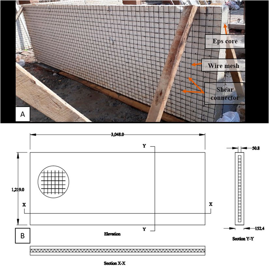
Figure 1. (A)Sandwich panel comprise of wire mesh and EPS core, (B)Schematic diagram of sandwich panel (all dimensions are in mm).
2.1 Mechanical properties of materials
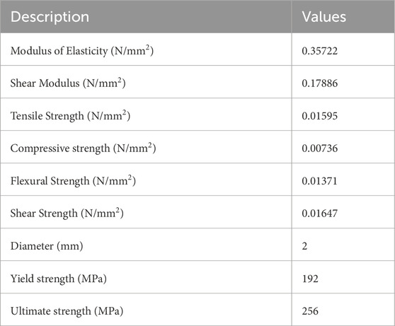
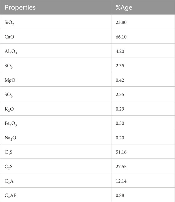
The mechanical properties of EPS and steel were analyzed to understand their load-bearing behavior. The properties of EPS and galvanized steel wire are provided in Table 1. Additionally, oxide and mineral compositions of the Ordinary Portland Cement (OPC) Type I used in this study are detailed in Table 2. Locally available soil was used to prepare the stabilized mud mix for casting the panels wythes. The Atterberg limits, specific gravity, optimum moisture content and dry density of the soil were determined and is given in the Supplementary Tables S3, S4. According to the unified soil classification system the soil was classified as silty clay. The soil was mixed with 10% cement and 1% straw (10–15 mm length) by weight of dry soil.
2.2 Casting of SMIPs
Two full scale SMIP’s (Fp-1 and FP-2) were constructed for flexure testing. Each SMIP was 152.4 mm thick, with a central EPS core 51 mm and 51 mm thick mud mortar wythes on either side. The panels were setup vertically, with their width perpendicular to the ground and supported by wooden planks as shown in Figure 2A). Three SMIP’s were constructed for diagonal tension testing (DT-1, DT-2 and DT-3), three samples for compression test (CS1, CS2 and CS3) and 3 (WAS-1, WAS-2 and WAS-3) for water absorption test. The EPS core thickness for diagonal, compression and water absorption specimen are 102 mm.
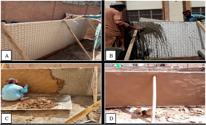
Figure 2. Casting of SMIP’s (A) sprinkling water (B) application of grout (C) stabilized mud plastering (D) finished surface with trowel.
The SMIP was erected by using wooden supports, placed at each corner on both sides and at mid for the flexure samples. After the panels were setup, water was sprinkled on them to remove dust and get wet surface for the application of mud plaster. Water cement grout was then applied to both sides of the panels. Following the grout, a cement stabilized mud mix was applied by hand from a distance to ensure food adhesion and the surface was finished with a steel trowel to create a uniform wythe thickness. This procedure was followed for all the SMIPs. The entire casting process is illustrated in Figures 2A–D.
During the plastering of the panels, three 50 mm × 50 mm × 50 mm cubes were made from the stabilized mud mix. These cubes underwent a compressive strength test after 28 days of curing, according to ASTM C-109, to determine their compressive strength and modulus of elasticity. The results showed a compressive strength of 0.75 N/mm2 and a modulus of elasticity of 15.30 N/mm2 (ASTM, 2020).
The SMIPs were cured at ambient temperature by sprinkling water on the wythes every 24 h for 28 days. While traditional mud construction usually does not require curing as no cementitious material is used, the cement-stabilized mud in this study needed curing to ensure proper cement hydration. The SMIPs were kept in an uncovered ambient environment until testing.
2.3 Test setup and instrumentation
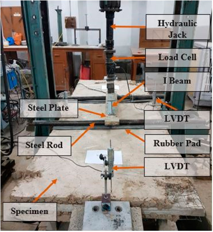
Flexural testing was conducted according to ASTM Standard C 78-02 to analyze the flexural behavior of SMIPs (Amran et al., 2016; ASTM, 2017b). The SMIPs were positioned on hinge and roller supports with a center-to-center distance of 2,438 mm, allowing for a 304.8 mm overhang on both sides, as depicted in Figure 3. Linear Variable Displacement Transducers (LVDTs) were strategically placed: two at the mid-span edges and one at each end of the SMIPs to measure deflection or rise of the SMIP. All LVDTs recorded positive values during contraction and negative values during elongation, with data automatically logged by a data logger.
For applying the load, a universal testing machine equipped with a hydraulic system capable of exerting up to 200 kN was used. The loading rate for both monotonic and cyclic loading was set at 10 mm/min. A W-shaped steel beam facilitated the transfer of load from the hydraulic jack to the steel plate and then to solid round steel bars (diameter 50 mm) positioned at specified locations on the SMIP. Figure 4 illustrates the experimental setup of SMIPs under flexural loading, focusing on their structural response as one-way slabs under load.
For the first flexural panel (FP-1), the load was applied while monitoring the deformations. The flexural panel (FP-2), was subjected to cyclic loading with three cycles (loading and unloading) for each load increment (1, 2, 3 and 4 kN). The test was conducted using load control, with an incremental load of 1 kN. After each increment, the load was reduced to zero. This process was repeated until the failure of FP-2. Detailed specifications of the specimens, including dimensions, composition, and testing parameters, can be found in the Supplementary Material.
Additionally, the stress at failure for a simply supported beam under loading, as per Equation 1 in ASTM C78 (ASTM, 2017b), was employed to analyze the results.
Where, R = Bending stress in MPa.
P = Maximum applied load indicated by the testing machine in N.
l = Span length in mm.
b = Average width of the specimen in mm.
d = Average thickness of the specimen in mm.
Diagonal tension tests followed ASTM E-519 standards (ASTM, 2022). Samples were positioned diagonally in loading shoes to transfer uniaxial loads from the hydraulic actuator. Two displacement sensors, with a gauge length of 33.5″, were installed diagonally—one in tension and one in compression—1.4 feet from the top and 1 foot from each end as shown in the Figure 5A. These sensors along with the load cell were connected to a data logger, as shown in Figure 5B. The tests aimed to determine the shear strength of the SMIPs. Three samples were tested; one was strengthened at the corners due to local failure and then tested again.
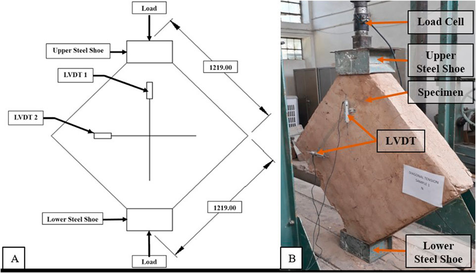
Figure 5. (A) Schematic diagram of diagonal tension test (dimensions are in mm) (B) Shear test setup of SMIPs.
The three compression SMIPs (CS1, CS2, and CS3) were tested following ASTM E-447 standards (ASTM, 2017a). The schematic diagram is as shown in the Figure 6A. Each specimen was positioned centrally on a layer of wet sand placed on the lower plate of the UTM. Additional wet sand was placed on top of each sample, and a 2 ft × 2 ft plate was placed over the sand to ensure uniform load distribution as shown in the Figure 6B. The sand served to provide a smooth surface for loading.
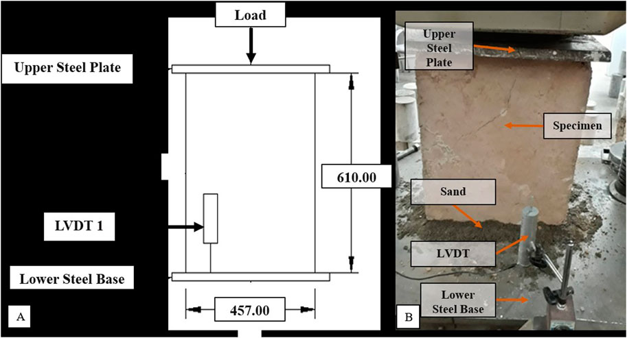
Figure 6. (A) Schematic diagram of compression test (dimensions are in mm) (B) Compression test setup.
LVDT was installed to measure vertical deformation in the compression samples. Initially, a 20 mm dial gauge was selected for CS1, anticipating minimal vertical deformation. However, it was found that the gauge reached its maximum capacity of 20 mm while deformation continued. Consequently, for CS2 and CS3, a 50 mm LVDT was utilized as shown in the Figure 6B. Water absorption test was carried out according to ASTM D 559 – 03 (ASTM, 2012). Total of three samples were constructed. All the specimen of SMIP after curing for 28 days were then placed in the water tank for 24 h in order to find out the water absorption capacity of the specimen.
3 Results and discussion
3.1 Load-displacement relationship
For the first flexural panel (FP-1), the load was applied slowly, and deformations were monitored. The second flexural panel (FP-2), was subjected to the cyclic loading with three cycles (loading and unloading) for each load increment (1, 2, 3 and 4 kN). The test used a load control method, with incremental loads of 1 kN applied and reduced to zero after each increment until FP-2 failed.
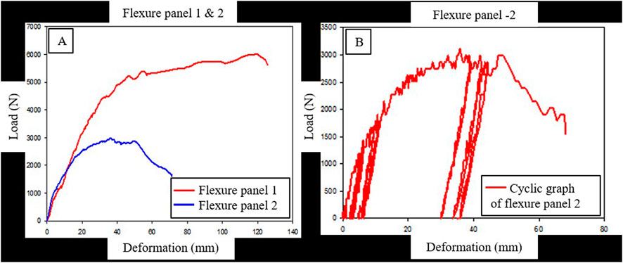
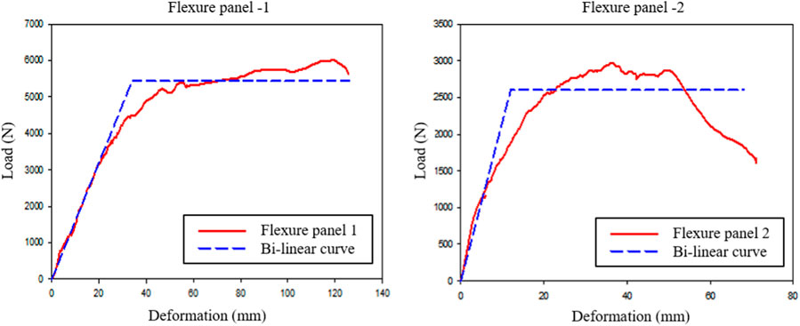
The load versus displacement curve for FP-1 and FP-2 is shown in Figure 7A. The ultimate load for FP-1 and FP-2 was 6 kN and 3 kN, respectively, with corresponding displacements at ultimate load of 119.83 mm and 36.04 mm. The maximum deformations for both panels were recorded as 123 mm and 66 mm, respectively. The cyclic loading graph of FP-2 is shown in Figure 7B.
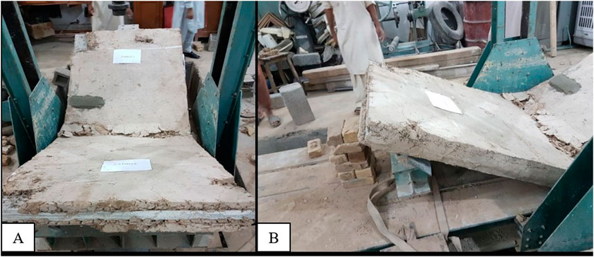
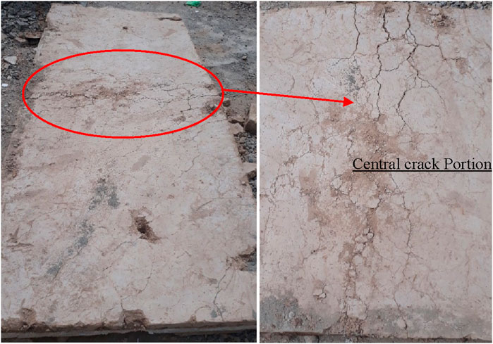
The behavior of the flexural panels under different loading conditions can be observed in the Figure 7. From Figure 7A, it can be seen that as the load increases, the deformations at the middle also increase. At a load of 6000 N, deformation of 119.83 mm was achieved, indicating that the system is very ductile in bending. In contrast, for the cyclic loaded FP-2 load was applied in increments of 1 kN (0.1 ton). During the first two load increments, only small deformations were observed. However, when the load was increased from 2 kN to 3 kN (0.2–0.3 tons), very large permanent deformations occurred as shown in Figure 7B. When the load cycle of 4 kN (0.4 tons) began, the sample could no longer withstand more than 3 kN (0.3 tons) and suddenly collapsed, as shown in Figure 8. This sudden failure was considered due to a patch of the wooden support at the top mid-location as shown Figure 9A which was later filled with mud. Additionally, a crack at the center, as shown in Figure 9B, contributed to the failure. Bi-linear idealizations for both panels are presented in Figure 10. The initial stiffness values were 3 kN/mm for FP-1 and 1.2 kN/mm for FP-2.
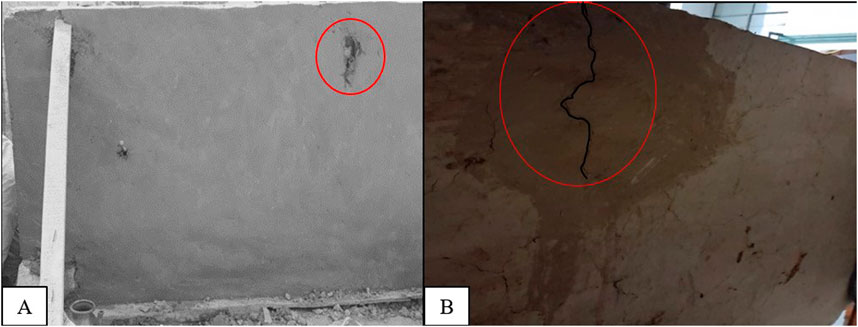
Figure 9. Patch at the center of FP-2 (A) Patch at center encircle in red (B) Crack encircled in red.
Initially, minor cracks appeared in the lower wythes of the FP-1. The panel shows a linear elastic response. While further increasing load caused these minor cracks to widen and new cracks to form, especially in the lower wythe within the middle third region, where stresses and bending moments are highest (Fernando et al., 2017; Bishnoi et al., 2021; Mohamad et al., 2014). Most cracks occurred in the middle and extended across the width of the FP-1 without spalling of mud as shown in Figure 11.
Ductility is a crucial factor indicating a structure’s ability to undergo post-yield/plastic deformation and dissipate energy, thus reflecting its capacity to endure significant inelastic deformations before failure (Spadea et al., 1998). In this study, deflection ductility (µΔ) for the SMIPs is calculated, which is for 3.7 and 5.1 for FP-1 and FP-2 respectively. Deflection ductility is the ratio of ultimate deformation (Δu) to yield deformation (Δy) (Özkılıç et al., 2023). A higher deflection ductility (µΔ) means the structure can undergo substantial deformation before reaching the critical failure point, making it highly recommended for earthquake-resistant structures (Said and Razak, 2016). Additionally, the failure stress under flexural loading was calculated using from ASTM C78 for SMIP, EPS-based lightweight concrete sandwich walls panel (LCSWP), precast concrete sandwich panel (PCSP), reinforced mud sandwich panels RMSPs Equation 1 and precast lightweight foam concrete sandwich panels (PLFCSP) (Fernando et al., 2017; Daniel Ronald Joseph et al., 2018; Sarwar et al., 2024; Mohamad et al., 2014). The results revealed that the failure stress of SMIPs was higher than that of the LCSWP but lower than that of the PCSP and PLFCSP, and similar to that of RMSP, as illustrated in Figure 12.
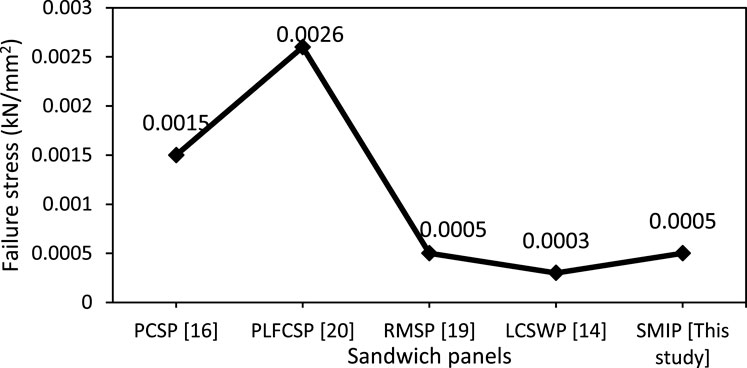
Figure 12. Comparison between failure stress (kN/mm2) of SMIP and other sandwich panels (previous studies).
3.2 Load-overhang end deformation (OED)
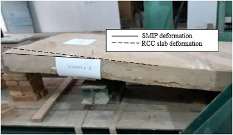
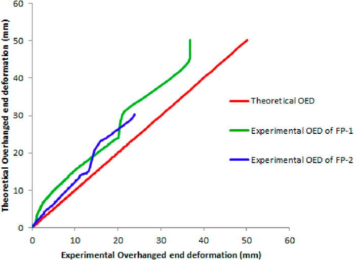
From the flexure loading mechanism, it was observed that the ends of a panel along its length rise as the mid-span deflects, a behavior confirmed during the experiment as shown in the Figure 14. At an ultimate load of 3 kN, the uplift at the overhang portion was recorded at 36.9 mm while the theoretically calculated was 50.2 mm. At a load of 6 kN, the center span deformation was recorded at 119.83 mm, and the uplift deformation was 36.9 mm. For the same load, the uplift deformation at the overhang portion was 29% of the center span deformation. Similar to the mid-span deflection, the rise of the overhang portion of the panel was linear in the early loading stage, but beyond approximately 3 kN of loading, nonlinear behavior was observed.
3.3 Sandwich action
The overhanging part of the SMIPs exhibits a slight deviation from its original position, resulting in a hogging shape, as shown in Figure 13. To analyze the sandwich effect, graphs were created to compare the experimental and predicted deformations at the cantilever ends of the panels Figure 14, using principle of similarity of triangles.
Initially, both panels closely follow the theoretical predictions, indicating linear elastic behavior. For FP-1, the experimental OED begins to deviate from the theoretical line as the load increases, showing greater deformations due to cracks and plastic deformation. FP-2 also initially aligns with the theoretical OED but diverges sooner, indicating earlier onset of damage due to cyclic loading and the preexisting crack at center. The experimental OEDs of both panels eventually fall below the theoretical predictions, demonstrating the sandwich effect, where layer interactions reduce overall deformation and enhance stability.
3.4 Failure of SMIP
As the load increases, in the beginning, minor cracks appeared in the lower wythes of the SMIP. Initially the panels show a linear elastic response. While further increasing load caused these minor cracks to widen and new cracks to form, especially in the lower wythe within the middle third region, where stresses and bending moments are highest (Fernando et al., 2017; Bishnoi et al., 2021; Mohamad et al., 2014). Most cracks occurred in the middle and extended across the width of the SMIPs.
For the cyclic loaded FP-2, the load was incrementally applied in steps of 1 kN (0.1 ton). Initially, only minor deformations were observed during the first two load increments. However, a significant change occurred when the load increased from 2 kN to 3 kN (0.2 to 0.3 tons), resulting in substantial permanent deformations in FP-2. At the start of the 4 kN (0.4 tons) load cycle, the panel could no longer sustain more than 3 kN (0.3 tons), as illustrated in Figure 7B, leading to a sudden collapse depicted in Figure 8. The abrupt failure of FP-2 was primarily attributed to a weak patch due to the wooden support at the top mid-location, shown in Figure 9A, which was subsequently filled with mud. Additionally, a central crack, as highlighted in Figure 9B, further compromised the panel’s integrity. These defects collectively facilitated the panel’s inability to bear the increase.
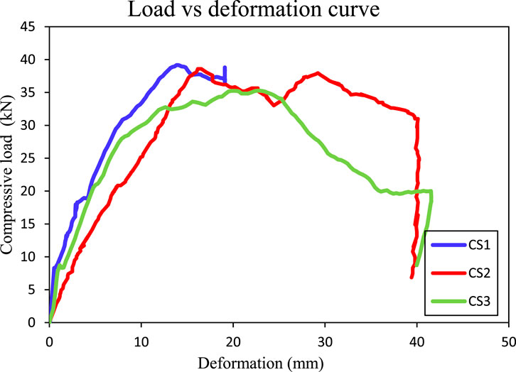
The Figure 15 illustrates the compressive behavior of three specimens (CS1, CS2, and CS3) under loading conditions. Initially, all specimens exhibit elastic behavior, with the compressive load increasing linearly with deformation. CS1 reaches a peak load of approximately 40 kN at around 20 mm deformation. However, it is important to note that the displacement sensor used during the CS1 test was limited to measuring up to 20 mm. This limitation means that CS1’s full deformation was not captured, and it is expected that CS1 would have exhibited similar deformation behavior to CS2 and CS3 if a more capable sensor had been used. Despite this, CS1 demonstrates a high load-bearing capacity and significant residual strength, as indicated by the post-peak load maintenance and fluctuations.
CS2 reaches a peak load of around 39 kN at approximately 17 mm deformation, with a maximum deformation of 40.24 mm. Due to a pre-existing crack in the middle of CS2, its initial stiffness is lower compared to CS1 and CS3. CS3 reaches a peak load of about 35 kN at 22 mm deformation, with a maximum deformation of 41.56 mm. After the peak, CS3 demonstrates a gradual decrease in load capacity. For the CS2 and CS3 tests, a sensor with a measurement capacity of up to 50 mm was used, ensuring that their full deformation behavior was captured.
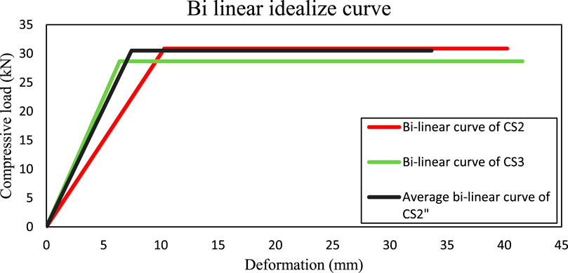
Bi-linear idealizations for CS2 and CS3 are presented in Figure 16. The initial stiffness values are 3 kN/mm for CS2 and 4.5 kN/mm for CS3, with an average stiffness of 4.1 kN/mm. Although the ductility of CS1 cannot be calculated due to the sensor’s limitation in capturing its ultimate deformation, its initial stiffness was found to be 5.7 kN/mm. The ductility ratios for CS2 and CS3 are 7.8 and 8.9, respectively, with an average ductility ratio of 8.3.
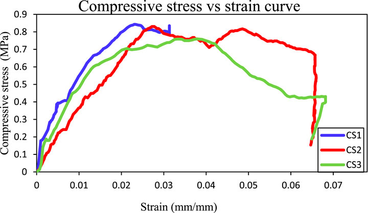
Figure 17 shows that CS1, CS2, and CS3 exhibit peak strengths of 0.861 MPa, 0.831 MPa, and 0.760 MPa, respectively. The corresponding strains for these values are 0.0313 mm/mm for CS1, 0.0278 mm/mm for CS2, and 0.0378 mm/mm for CS3. The Young’s moduli are 65 MPa for CS1, 37 MPa for CS2, and 64 MPa for CS3. The compressive strength of CSs was found to be nearly identical among the specimens with the average value of 0.82 MPa but lower than that of the cube specimens, which had a compressive strength of 1.06 MPa. Despite the lower compressive strength of the CSs compared to the cubes, the mud remained stable due to the presence of the sandwich panel, preventing it from buckling like a pure mud sample of the same size and thickness.
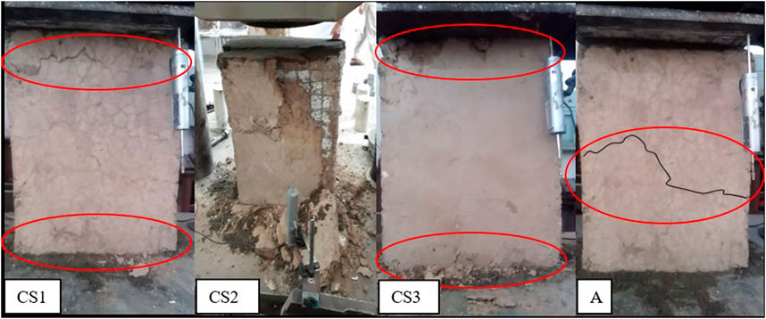
The behavior of the first and third compressive specimens (CS1 and CS3) was similar as shown in the Figure 17. As shown in Figure 18 in both CS1 and CS3, cracks appeared at the top and bottom of the sample at the ultimate load, specifically within a region extending up to 3 inches from both ends of the samples (Daniel Ronald Joseph et al., 2023; Mugahed Amran et al., 2016). In the CS2, chunks of mud spalling were observed at the ultimate load. Damage occurred on half of the top and a quarter of the bottom side of the sample. Both CS1 and CS3 experienced localized damage at the top region, with the depth of damage extending 3 inches from the top edge. In contrast, CS2 exhibited significant mud loss from the top half and partially from the bottom side. The primary mode of failure as shown in Figure 19 was the buckling of the wire mesh, detachment and spalling of mud from the specimens (Daniel Ronald Joseph et al., 2023).
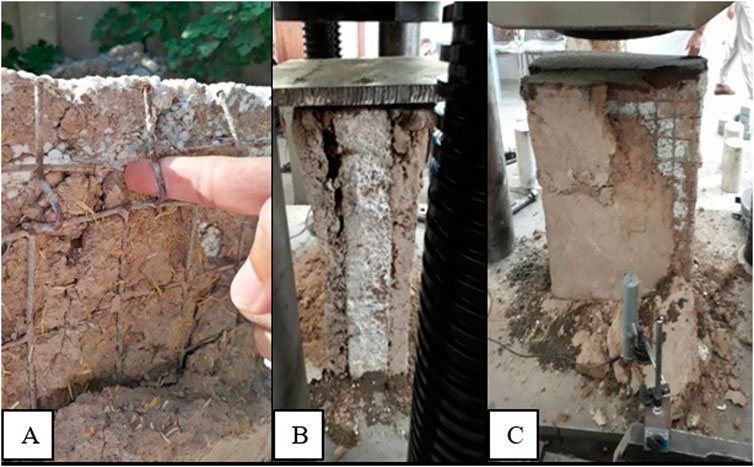
Figure 19. Failure mechanism of CSs (A) buckling of wires (B) detachment of mud (C) chunks of mud spalling.
The Figure 20 illustrates the ultimate load-carrying capacities of various structural panels, including PA4, PC1, FCS-F1, GA6, RCSP, and CSs (Benayoune et al., 2007; Daniel Ronald Joseph et al., 2023; Mohamad et al., 2017; Gara et al., 2012; Mugahed Amran et al., 2016; Khattak, 2024). PA4 exhibits the highest capacity of 1,075.00 kN/m, followed by PC1 of 917.60 kN/m, FCS-F1 of 830.67 kN/m, and GA6 of 616.80 kN/m. RCSP has a capacity of 188.68 kN/m, while CSs have the lowest of 83.03 kN/m (Khattak, 2024). Furthermore, when comparing the load-carrying capacities of CS and Reinforced Concrete Structural Panels (RCSPs), RCSP panels, with a capacity of 188.68 kN/m, can support loads for up to nine stores (Khattak, 2024). In contrast, mud panels (CSs) have a load-carrying capacity of 83.03 kN/m, allowing them to support approximately four stores under the same conditions. This indicates that while RCSP and other panels are suitable for high-rise structures, mud panels are a viable option for low-rise buildings due to their sufficient load-bearing capacity and sustainability advantages. In order to enhance the compressive capacity of SMIP CSs, it is recommended to increase the thickness of the mud plaster from 2 inches. This increase in thickness would likely provide additional stability and improve the overall compressive strength of the specimens.
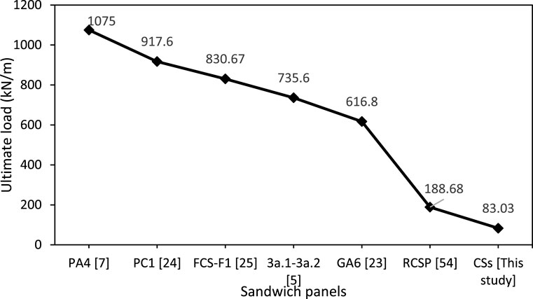
Figure 20. Comparison between failure force (kN/m) of CSs and other sandwich panels (previous studies).
The behavior of diagonal tension specimens was also studied in terms of cracking pattern, mode of failure, strain, and in-plane shear capacity. During the application of diagonal compression load, the vertical diagonal shortens, whereas the horizontal diagonal elongates. All the diagonal compression specimens were tested until collapse or until the load was reduced to below 80% of the peak load. The response was recorded in terms of total load versus horizontal and vertical displacements, using linear displacement sensors to measure these displacements. The total shear strain was calculated as the sum of strains along the two diagonals according to Equation 2 (ASTM, 2022). The applied load was used to evaluate the shear stress as per Equation 3 (ASTM, 2022). The shear stress versus strain plot is shown in Figure 21A. The nature of the shear stress versus strain curves is linear, as the cracking starts curves become non-linear.
where,
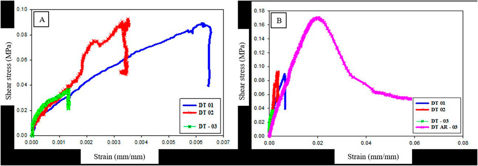
Figure 21. Shear stress vs. strain graph (A) local failure of all Samples (B) failure of strengthen sample at ultimate load/stress.
Figure 21B illustrates the relationship between shear stress (MPa) and shear strain (mm/mm) for four specimens: DT 01, DT 02, DT 03, and DT AR-03. DT 01, exhibits a linear increase in shear stress with strain, peaking at approximately 0.04 MPa at 0.0012 mm/mm before sharply dropping, indicating failure. For specimen DT 02, there is a sudden change in the slope of the shear stress-strain plot, which may be attributed to readjustment of the loading shoe of the specimen around a stress of 0.05 MPa. The peak strength was found out to be around 0.09 MPa at 0.0035 mm/mm and then declining sharply. The DT 03 also peaks at approximately 0.095 MPa at 0.005 mm/mm before a sharp drop. This sharp drop was because of the local crushing occurred at the loading shoes Figures 22A–C, indicating some out-of-plane bending due to accidental eccentricity caused by imperfections in construction or non-alignment of the centerline of the loading/supporting shoe, and the specimens (In-plane behavior of expanded polystyrene core reinforced concrete sandwich panels). This crushing failure occurred at very low applied stress at the loading shoes, which prevented the determination of the ultimate capacity and allowed only the measurement of the elastic capacity. In contrast, DT AR 03, continues to rise beyond the peaks of the other graph, reaching a maximum shear stress of about 0.17 MPa at 0.020 mm/mm before starting to decline, indicating it has higher resistance to shear stress and can withstand greater shear strain before failure compared to DT 01, DT 02, and DT 03. This was because one of the three samples was strengthened at the corners with cement-rich concrete (1:1:1.5) and cured for 28 days prior to testing, as shown in Figure 22D. The strengthening helped in capturing the ultimate shear behavior of the SMIP, and the shear strength was found to be 0.17 MPa with corresponding shear strain (mm/mm) 0.0208 while shear modulus was 12.5 MPa. Figure 21B shows that the SMIP has large shear deformation.
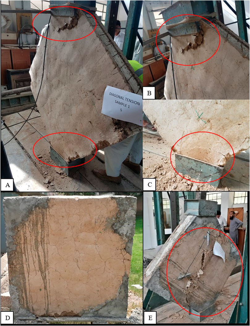
Figure 22. (A) Shear failure of the SMIP (B) failure at bottom shoe (C) failure at top shoe (D) DT-AR-03 strengthened sample (E) DT-AR-03 failure at ultimate load.
The ultimate shear load of different sandwich panels is shown in the Figure 23. It is clear that the shear strength or load carrying capacity of SMIP is lower than that of Concrete sandwich panels but it can be increased by increasing the strength of mud used (Gara et al., 2012; Ahmad and Singh, 2021b).
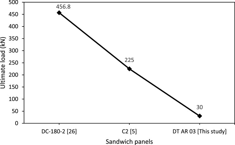
Figure 23. Comparison between failure force (kN) of DTs and other sandwich panels (previous studies).
Water absorption tests for (SMIPs) were conducted following ASTM D 559-03. Three specimens, each measuring 2 ft high, 1 ft wide, and 8 in thick, were cured for 28 days before testing. The specimens were submerged in water for 24 h, then towel-dried and re-weighed to assess their water absorption capacity. The measured water absorption values were 14.1%, 12.3%, and 15.3%, with an average water absorption capacity of 13.8% that is within the limits (Jackson and Dhir, 1997).
4 Conclusion
This study evaluates the performance of an innovative composite structural system composed of structural mud insulated panels. The panels were tested under different types of loading, and their load-deflection and stress-strain responses were monitored. The results were analyzed based on ultimate load capacity, maximum stress, corresponding strain, maximum deflection, ductility, failure modes, and water absorption. The experimental findings led to the following conclusions:
The flexural tests reveal the critical role of ductility and initial stiffness in determining the ultimate load capacity and deformation characteristics of structural panels. This suggests that optimizing these properties can lead to more resilient construction materials. Additionally, the compressive strength results, although lower than traditional concrete panels, show that SMIPs can maintain structural stability under significant loads due to their unique sandwich design, preventing buckling and enhancing durability.
Moreover, the shear strength evaluation underscores the importance of material enhancement and structural reinforcement in improving the overall performance of SMIPs. The observed behavior under diagonal tension tests indicates that targeted reinforcement can substantially increase the shear capacity, making these panels more versatile for various construction applications.
The study’s generalizable conclusion is that while SMIPs may not yet match the performance of conventional concrete panels in some aspects, their sustainable attributes and satisfactory structural properties make them a promising alternative for environmentally friendly construction. Future research should focus on material enhancements and design optimizations to further improve the performance and applicability of SMIPs in broader construction contexts, potentially revolutionizing the approach to sustainable building practices.
Data availability statement
The raw data supporting the conclusions of this article will be made available by the authors, without undue reservation.
Author contributions
AK: Writing–original draft, Visualization, Validation, Software, Methodology, Investigation, Formal Analysis, Data curation. MA: Resources, Project administration, Writing–review and editing, Supervision, Methodology, Conceptualization. DD: Validation, Writing–review and editing, Supervision, Methodology, Conceptualization. MAK: Visualization, Investigation, Formal Analysis, Writing–review and editing, Validation, Methodology. MA: Project administration, Writing–review and editing, Validation, Methodology. MSK: Writing–review and editing, Visualization, Validation, Methodology, Investigation, Formal Analysis. MMSS: Writing–review and editing, Supervision, Resources, Project administration, Methodology, Investigation, Funding acquisition.
Funding
The author(s) declare that financial support was received for the research, authorship, and/or publication of this article. The research is partially funded by the Ministry of Science and Higher Education of the Russian Federation as part of the World-class Research Center program: Advanced Digital Technologies (contract No. 075-15-2022-311 dated 20.04.2022).
Conflict of interest
Author MA was employed by Omicron AEC Inc.
The remaining authors declare that the research was conducted in the absence of any commercial or financial relationships that could be construed as a potential conflict of interest.
Publisher’s note
All claims expressed in this article are solely those of the authors and do not necessarily represent those of their affiliated organizations, or those of the publisher, the editors and the reviewers. Any product that may be evaluated in this article, or claim that may be made by its manufacturer, is not guaranteed or endorsed by the publisher.
Supplementary material
The Supplementary Material for this article can be found online at: https://www.frontiersin.org/articles/10.3389/fmats.2024.1495750/full#supplementary-material
References
Abdelghani, B. (2003). “Precast concrete sandwich panel as A building system,” in Engineering, materials science.
Agarwal, A. (1982). “Research: mud as a traditional building material,” in The changing rural habitat; volume I: case studies. Editor B. B. Taylor (Singapore: Aga Khan Award for Architecture).
Ahmad, A., and Singh, Y. (2021a). Flexural behavior of Expanded Polystyrene core Reinforced Concrete Sandwich Panels with different construction methods and end conditions. Structures 34, 2900–2911. doi:10.1016/j.istruc.2021.09.051
Ahmad, A., and Singh, Y. (2021b). In-plane behaviour of expanded polystyrene core reinforced concrete sandwich panels. Constr. Build. Mater. 269, 121804. doi:10.1016/j.conbuildmat.2020.121804
Ahmed, H. U., Mohammed, A. S., Faraj, R. H., Abdalla, A. A., Qaidi, S. M. A., Sor, N. H., et al. (2023). Innovative modeling techniques including MEP, ANN and FQ to forecast the compressive strength of geopolymer concrete modified with nanoparticles. Neural Comput. and Applic 35 (17), 12453–12479. doi:10.1007/s00521-023-08378-3
Alam, I., Naseer, A., and Shah, A. A. (2015). Economical stabilization of clay for earth buildings construction in rainy and flood prone areas. Constr. Build. Mater. 77, 154–159. doi:10.1016/j.conbuildmat.2014.12.046
Amran, Y. H. M., Rashid, R. S. M., Hejazi, F., Safiee, N. A., and Ali, A. A. A. (2016). Response of precast foamed concrete sandwich panels to flexural loading. J. Build. Eng. 7, 143–158. doi:10.1016/j.jobe.2016.06.006
ASTM (2012). D559 standard test methods for wetting and drying compacted soil-cement mixtures (withdrawn 2012). Available at: https://www.astm.org/d0559-03.html (Accessed July 17, 2024).
ASTM (2017a). E447 standard test methods for compressive strength of masonry prisms. Available at: https://www.astm.org/e0447-74.html (Accessed July 25, 2024).
ASTM (2017b). Standard test method for flexural strength of concrete (using simple beam with third-point loading). Available at: https://www.astm.org/c0078-02.html (Accessed July 14, 2024).
ASTM (2020). Standard test method for compressive strength of hydraulic cement mortars (using 2-in. Or [50-mm] cube specimens). Available at: https://www.astm.org/c0109_c0109m-20.html (Accessed July 25, 2024).
ASTM (2022). Standard test method for diagonal tension (shear) in masonry assemblages. Available at: https://www.astm.org/e0519_e0519m-22.html (Accessed July 25, 2024).
Benayoune, A., Abdul Samad, A. A., Trikha, D., and Ali, A. (2001). Behaviour of precast reinforced concrete sandwich panels with continuous shear truss connectors. J. Inst. Eng. Malays. 62, 59–66.
Benayoune, A., Samad, A. A. A., Abang Ali, A. A., and Trikha, D. N. (2007). Response of pre-cast reinforced composite sandwich panels to axial loading. Constr. Build. Mater. 21 (3), 677–685. doi:10.1016/j.conbuildmat.2005.12.011
Benayoune, A., Samad, A. A. A., Trikha, D. N., Abang Ali, A. A., and Ashrabov, A. A. (2006). Structural behaviour of eccentrically loaded precast sandwich panels. Constr. Build. Mater. 20 (9), 713–724. doi:10.1016/j.conbuildmat.2005.02.002
Benayoune, A., Samad, A. A. A., Trikha, D. N., Ali, A. A. A., and Ellinna, S. H. M. (2008). Flexural behaviour of pre-cast concrete sandwich composite panel – experimental and theoretical investigations. Constr. Build. Mater. 22 (4), 580–592. doi:10.1016/j.conbuildmat.2006.11.023
Benhelal, E., Zahedi, G., Shamsaei, E., and Bahadori, A. (2013). Global strategies and potentials to curb CO2 emissions in cement industry. J. Clean. Prod. 51, 142–161. doi:10.1016/j.jclepro.2012.10.049
Bishnoi, U., Danie Roy, A. B., and Kwatra, N. (2021). Out of plane performance of novel concrete sandwich panel using different geosynthetics. Constr. Build. Mater. 300, 124186. doi:10.1016/j.conbuildmat.2021.124186
Bistline, J., and Rai, V. (2010). The role of carbon capture technologies in greenhouse gas emissions-reduction models: a parametric study for the U.S. power sector. Energy Policy 38 (2), 1177–1191. doi:10.1016/j.enpol.2009.11.008
Bush, T. D., and Stine, G. L. (1994). Flexural behavior of composite precast concrete sandwich panels with continuous truss connectors. PCI J. 39 (2), 112–121. doi:10.15554/pcij.03011994.112.121
Bush, T. D., and Wu, Z. (1998). Flexural analysis of prestressed concrete sandwich panels with truss connectors. pcij 43 (5), 76–86. doi:10.15554/pcij.09011998.76.86
Carbonari, G., Cavalaro, S. H. P., Cansario, M. M., and Aguado, A. (2012). Flexural behaviour of light-weight sandwich panels composed by concrete and EPS. Constr. Build. Mater. 35, 792–799. doi:10.1016/j.conbuildmat.2012.04.080
Cascione, V., Maskell, D., Shea, A., and Walker, P. (2019). A review of moisture buffering capacity: from laboratory testing to full-scale measurement. Constr. Build. Mater. 200, 333–343. doi:10.1016/j.conbuildmat.2018.12.094
Celik, K., Meral, C., Petek Gursel, A., Mehta, P. K., Horvath, A., and Monteiro, P. J. M. (2015). Mechanical properties, durability, and life-cycle assessment of self-consolidating concrete mixtures made with blended portland cements containing fly ash and limestone powder. Cem. Concr. Compos. 56, 59–72. doi:10.1016/j.cemconcomp.2014.11.003
CityChangers (2024). Natural materials in construction guide. Available at: https://citychangers.org/natural-materials-in-construction/(Accessed July 10, 2024).
Dai, T., Fang, C., Liu, T., Zheng, S., Lei, G., and Jiang, G. (2024). Waste glass powder as a high temperature stabilizer in blended oil well cement pastes: hydration, microstructure and mechanical properties. Constr. Build. Mater. 439, 137359. doi:10.1016/j.conbuildmat.2024.137359
Daniel Ronald Joseph, J., Prabakar, J., and Alagusundaramoorthy, P. (2023). Experimental and analytical investigations on the failure modes of concrete sandwich panels under axial compression. Eur. J. Environ. Civ. Eng. 27 (2), 733–762. doi:10.1080/19648189.2022.2063948
Daniel Ronald Joseph, J., Prabakar, J., and Alagusundaramoorthy, P. (2018). Flexural behavior of precast concrete sandwich panels under different loading conditions such as punching and bending. Alexandria Eng. J. 57 (1), 309–320. doi:10.1016/j.aej.2016.11.016
Daniel Ronald Joseph, J., Prabakar, J., and Alagusundaramoorthy, P. (2017). Precast concrete sandwich one-way slabs under flexural loading. Eng. Struct. 138, 447–457. doi:10.1016/j.engstruct.2017.02.033
Danso, H., Martinson, D. B., Ali, M., and Williams, J. B. (2015). Physical, mechanical and durability properties of soil building blocks reinforced with natural fibres. Constr. Build. Mater. 101, 797–809. doi:10.1016/j.conbuildmat.2015.10.069
Fernando, P. L. N., Jayasinghe, M. T. R., and Jayasinghe, C. (2017). Structural feasibility of Expanded Polystyrene (EPS) based lightweight concrete sandwich wall panels. Constr. Build. Mater. 139, 45–51. doi:10.1016/j.conbuildmat.2017.02.027
Gara, F., Ragni, L., Roia, D., and Dezi, L. (2012). Experimental tests and numerical modelling of wall sandwich panels. Eng. Struct. 37, 193–204. doi:10.1016/j.engstruct.2011.12.027
Jackson, N., and Dhir, R. K. (1997). Civil engineering materials. United Kingdom: Macmillan Education.
Kan, A., and Demirboğa, R. (2009). A new technique of processing for waste-expanded polystyrene foams as aggregates. J. Mater. Process. Technol. 209 (6), 2994–3000. doi:10.1016/j.jmatprotec.2008.07.017
Khattak, N. (2024). Strength and structural behavior study of locally produced reinforced concrete sandwiched panels (RCSPs).
Liang, K., Sun, P., and Wang, D. (2024). Quantitative analysis of deformation performance for skew slab based on deformation energy decomposition method of triangular prism element. Structures 63, 106447. doi:10.1016/j.istruc.2024.106447
Liu, Y., Wang, B., Fan, Y., Yu, J., Shi, T., Zhou, Y., et al. (2024). Effects of reactive MgO on durability and microstructure of cement-based materials: considering carbonation and pH value. Constr. Build. Mater. 426, 136216. doi:10.1016/j.conbuildmat.2024.136216
Minke, G. (2006). Building with earth: design and technology of a sustainable architecture. Basel: Birkhäuser Basel. doi:10.1007/3-7643-7873-5
Mohamad, N., Goh, W. I., Abdullah, R., Samad, A. A. A., Mendis, P., and Sofi, M. (2017). Structural performance of FCS wall subjected to axial load. Constr. Build. Mater. 134, 185–198. doi:10.1016/j.conbuildmat.2016.12.133
Mohamad, N., Khalil, A. I., Abdul Samad, A. A., and Goh, W. I. (2014). Structural behavior of precast lightweight foam concrete sandwich panel with double shear truss connectors under flexural load. ISRN Civ. Eng. 2014, 1–7. doi:10.1155/2014/317941
Morel, J. C., Mesbah, A., Oggero, M., and Walker, P. (2001). Building houses with local materials: means to drastically reduce the environmental impact of construction. Build. Environ. 36 (10), 1119–1126. doi:10.1016/S0360-1323(00)00054-8
Mugahed Amran, Y. H., Abang Ali, A. A., Rashid, R. S. M., Hejazi, F., and Safiee, N. A. (2016). Structural behavior of axially loaded precast foamed concrete sandwich panels. Constr. Build. Mater. 107, 307–320. doi:10.1016/j.conbuildmat.2016.01.020
Ngowi, A. B. (1997). Improving the traditional earth construction: a case study of Botswana. Constr. Build. Mater. 11 (1), 1–7. doi:10.1016/S0950-0618(97)00006-8
Özkılıç, Y. O., Karalar, M., Aksoylu, C., Beskopylny, A. N., Stel'makh, S. A., Shcherban, E. M., et al. (2023). Shear performance of reinforced expansive concrete beams utilizing aluminium waste. J. Mater. Res. Technol. 24, 5433–5448. doi:10.1016/j.jmrt.2023.04.120
Planas, N., Dzubak, A. L., Poloni, R., Lin, L.-C., McManus, A., McDonald, T. M., et al. (2013). Energy and environmental impacts of the use of CO2 as a solvent in hydrocarbon processes. J. Am. Chem. Soc. 135 (20), 7402–7405. doi:10.1021/ja4004766
Prakash, V., and Raj, A. (2016). Studies on stabilized mud block as a construction material. Int. J. Innovative Res. Adv. Eng. 3 (01).
Said, S. H., and Razak, H. A. (2016). Structural behavior of RC engineered cementitious composite (ECC) exterior beam–column joints under reversed cyclic loading. Constr. Build. Methods 107, 226–234.
Sarwar, M. W., Adil, M., Ullah, Z., Sikandar, M. A., Bashir, M. T., Baloch, Z., et al. (2024). Assessment of flexural performance of reinforced mud sandwich panels: experimental and numerical modeling approach. Innov. Infrastruct. Solut. 9 (7), 254. doi:10.1007/s41062-024-01570-x
Solomon, S., Qin, D., Manning, M., Marquis, M., Averyt, K., and Tignor, M. M. B. (2007). Climate change 2007: the physical science basis: contribution of working group I to the fourth assessment report of the intergovernmental panel on climate change. Cambridge, New York: Cambridge University Press.
Spadea, G., Bencardino, F., and Swamy, R. N. (1998). Structural behavior of composite RC beams with externally bonded CFRP. J. Compos. Constr. 2, 132–137. doi:10.1061/(ASCE)1090-0268(1998)2:3(132)
Tennant, A. G., Foster, C. D., and Reddy, B. V. V. (2016). Detailed experimental review of flexural behavior of cement stabilized soil block masonry. J. Mater. Civ. Eng. 28 (6), 06016004. doi:10.1061/(ASCE)MT.1943-5533.0001548
Walker, P., and Stace, T. (1997). Properties of some cement stabilised compressed earth blocks and mortars. Mat. Struct. 30 (9), 545–551. doi:10.1007/BF02486398
Keywords: sustainable construction, mud houses, mechanical properties, sandwiched panels structural mud insulated panels
Citation: Khan A, Adil M, Dan D, Khan MA, Ahmad M, Khan MS and Sabri MMS (2024) Assessment of mechanical performance of sustainable structural mud insulated panels. Front. Mater. 11:1495750. doi: 10.3389/fmats.2024.1495750
Received: 13 September 2024; Accepted: 15 October 2024;
Published: 01 November 2024.
Edited by:
Francesco Ascione, University of Salerno, ItalyReviewed by:
Nahla Hilal, University of Fallujah, IraqMarco Lamberti, Italian National Agency for New Technologies, Energy and Sustainable Economic Development (ENEA), Italy
Copyright © 2024 Khan, Adil, Dan, Khan, Ahmad, Khan and Sabri. This is an open-access article distributed under the terms of the Creative Commons Attribution License (CC BY). The use, distribution or reproduction in other forums is permitted, provided the original author(s) and the copyright owner(s) are credited and that the original publication in this journal is cited, in accordance with accepted academic practice. No use, distribution or reproduction is permitted which does not comply with these terms.
*Correspondence: Muhammad Salman Khan, c2FsbWFuQHRvbmdqaS5lZHUuY24=; Mahmood Ahmad, YWhtYWRtQHVuaXRlbi5lZHUubXk=; Muhammad Adeel Khan, YWRlZWxAdG9uZ2ppLmVkdS5jbg==
 Asad Khan
 Mohammad Adil
 Danhui Dan1
 Muhammad Adeel Khan
 Mahmood Ahmad
 Muhammad Salman Khan
 Mohanad Muayad Sabri Sabri