 Jian Zhou1
 Rui Zhong
- 1Ningbo Water Conservancy and Hydropower Planning and Design Institute Co. Ltd., Ningbo, China
- 2Shanghai Construction Groups, Shanghai, China
- 3School of Civil Engineering, Southeast University, Nanjing, China
- 4School of Civil Engineering, Southeast University, Nanjing, China
- 5Department of Civil, Architectural and Environmental Engineering, Missouri University of Science and Technology, Rolla, MO, United States
A full-scale hybrid beam consisting of a UHPC slab and FRP truss girder was fabricated. The novel side plate FRP joint characterized with improved load-carrying capacity, stiffness, and preferred failure mode along with the tailored shear connector validated in the previous studies of the authors were adopted. Its flexural performance was characterized and compared with that of hybrid beams employing NC or UHPC slab but I-profile girder. The failure of the proposed hybrid beam subjected to bending was pseudo ductile whereas those of the other two hybrid beams were brittle. The load-carrying capacity and stiffness of the proposed hybrid beam outperformed the other two hybrid beams with comparable dimensions and material properties.
1 Introduction
A number of advantages of fiber reinforced polymer (FRP) such as excellent corrosion resistance to aggressive environment agents, high stiffness-to-weight and strength-to-weight ratio, quick installation, and low maintenance requirements, make it an attractive alternative to traditional construction materials such as steel, wood and concrete (Koaik et al., 2017; Zhu et al., 2024; Hollaway, 2010; Gand et al., 2013). The building industry was the pioneer for the use of FRP in civil engineering sector. Glass fiber reinforced polymer (GFRP) was used for Radomes during the Second World War due to its transparency to radar or radio waves (Hollaway, 2010). By the 1970s consulting architects and civil engineers commenced to use FRP as semi-load-bearing infill panels for houses (Hollaway, 2010). FRP was introduced to civil engineering as a repair or strengthening material for degraded concrete structures in the 1980s (Fang et al., 2019; Seo et al., 2013; Floruţ et al., 2014; Al-Rousan et al., 2012; Al-Sunna et al., 2012; Teng et al., 2003; Zhao and Zhang, 2007; Zhao et al., 2014; Hollaway and Teng, 2008). The use of pultruded FRP profiles as principal load-carrying members is increasingly promoted by the advanced manufacturing process such as pultrusion (Hizam et al., 2018; Keller et al., 2007; Deskovic et al., 1995). The all-composite deck in bridge construction is one of the most developed systems (Keller, 2007). However, it suffers from several disadvantages: 1) the compressive flange is significantly weaker than the tensile flange due to the substantially lower compressive strength of FRP compared with its tensile strength as well as the local buckling phenomena; 2) the failure is catastrophic without warning because of the linear elastic behavior of FRP up to failure; and 3) the design is usually dictated by stiffness rather than strength which necessitate excessive use of composite materials to satisfy specific displacement requirements (Deskovic et al., 1995).
An established solution is to place a concrete slab on top of the FRP girder to form a stiffer hybrid system (Deskovic et al., 1995). The deflection of the FRP girder can be reduced which is also beneficial for avoiding the delamination failure and alleviating the flange buckling of FRP profile subjected to compression. Significant progress has been made to understand the performance of concrete slab - FRP girder hybrid beam (Neto and La Rovere, 2010; Correia et al., 2007; Canning et al., 1999; Zou et al., 2020). Nevertheless, focus was placed on the behavior of hybrid beams utilizing normal concrete (NC) in these investigations. The lack of ductility which can lead to catastrophic failure without warning remains an issue to be addressed. Ultra-high performance concrete (UHPC) is an advanced cementitious composites characterized with significantly improved compressive strength and elastic modulus, excellent ductility, and superior impact resistance compared with NC (Zhong et al., 2024; Zhong et al., 2021; Zhong and Zhang, 2023). These features may not only improve the structural stiffness but also enable a pseudo ductile failure. However, studies on the behavior of hybrid beams employing UHPC slab are limited (El-Hacha and Chen, 2012; Zhang et al., 2021; Zou and Wang, 2018). Furthermore, the inherent anisotropic nature of FRP hinders efficient utilization of FRP and limits the load-carrying capacity due to the limited transverse properties in comparison to the longitudinal ones (Bai and Keller, 2009). A clear loading path and the best material performance of each FRP member can be achieved in a truss system since each member is loaded in the longitudinal direction (Fang et al., 2019). The high axial strength also results in less material usage which can compensate the relatively expensive initial material cost of FRP compared with conventional construction materials. Therefore, it is believed to be a cost-effective and structurally efficient application for the FRP girder of a hybrid beam.
The overall performance of a UHPC slab - FRP truss hybrid beam (UHPC-TFRP-HB) is governed by the behavior of the FRP joint and the UHPC-FRP interface which represent structural discontinuities and associated stress localization. In general, there are three categories of joint technique: bonded joint, mechanical joint, and a combination of both. Bonded joints are less practical due to concerns of temperature vulnerability, long-term fatigue, and requirement of delicate quality control and assembly (Luo et al., 2016; Zou and Keller, 2005). Bolted joint suffers from limited resistance to out-of-plane load, rigidity under torsion, and stiffness along the minor axis due to the use of open section FRP profiles. A novel side plate joint for FRP truss was recently developed by the authors which integrates a steel U-shaped gusset plate (UGP) to reinforce the traditional bolted joint (Zou et al., 2023). The ultimate deflection was reduced by up to 33% and the load-carrying capacity of the proposed joint was improved by up to 63% (Zou et al., 2023). Note that there are also some innovative but less widely used joints for FRP composites (Luo et al., 2016; Bai and Yang, 2013; Wu et al., 2016). However, these joints are relatively sophisticated or require special components to form complex shapes. Robust shear connection enables the full composite action between the FRP truss and UHPC slab. Therefore, it is another key issue of paramount importance. A variety of shear connections have been proposed (Zou and Keller, 2005; Zou et al., 2018a; Zou et al., 2016; Zou et al., 2018b; Zou et al., 2021). Adhesive bonding may not be suitable for UHPC-TFRP-HB due to the insufficient bonding area (Yang et al., 2017) and vulnerability to temperature cycling (Luo et al., 2016). Bolted connection leads to discontinuity of fibers which is detrimental to the overall performance of structures. FRP rib, FRP shear key (FSK), and perforated FRP rib (PFR) suffer from the very limited shear strength of FRP which eventually compromises the overall performance of such shear connections. A tailored shear connection for UHPC-TFRP-HB was proposed and its superior performance with respect to slip modulus and shear capacity was validated in a previous study of the authors (Zhong et al., 2023).
The improved performance of the side plate FRP joint and the tailored UHPC-FRP shear connector have been well documented in previous studies of the authors. The essential concept of the novel FRP joint is to replace the open channel profiles with the closed section tubular profiles and reinforce the joint zone by a steel UGP. The tailor-made shear connector is formed by welding a perforated steel stick onto the base of the steel UGP and inserting steel rebars into the perforations. Interested readers are referred to (Zou et al., 2023) and (Zhong et al., 2023) for more detailed information of the design concept, improved performance, and underlying mechanisms. This study aims at characterizing the flexural behavior of a full-scale UHPC-TFRP-HB implementing such joint and shear connection at a structural level. The flexural behavior of the proposed hybrid beam was also compared with those reported in the literature adopting NC or UHPC as the slab but I-profile as the truss.
2 Sample preparation and test setup
A full-scale UHPC-TFRP-HB implementing a novel FRP joint and tailor-made shear connector was fabricated to assess its flexural behavior. The side plate FRP joint is characterized with improved load-carrying capacity, stiffness, and preferred failure mode (Zou et al., 2023). The tailored shear connector was validated as effective in previous study (Smith et al., 1998). The inherent drawback of limited transverse properties and the disadvantages of FRP structure such as premature failure of the compressive flange and limited stiffness can be overcome. The detailed properties of the UHPC and FRP are listed in Table 1 and Table 2, respectively. The rebars were Φ8/HRB400. The length, height and span of the hybrid beam are 3,700 mm, 980 mm and 3,100 mm, respectively. The dimension of the UHPC slab is 3,700 mm × 500 mm × 80 mm (length × width × thickness) as shown in Figure 1. Fifteen strain gauges in total were mounted on the top surface of the UHPC slab which are located at positions close to one end (C1 – C5), quarter span (C6 – C10), and middle span (C11 – C15) (Figure 1). All FRP profiles were made from 100 mm × 100 mm × 8 mm rectangular tubes. The length of the top and bottom chords of the FRP truss is 3,700 mm and 3,300 mm, respectively. The length of the vertical and diagonal FRP members is 700 mm and 990 mm, respectively. Detailed information of the FRP profiles is illustrated in Figure 2.
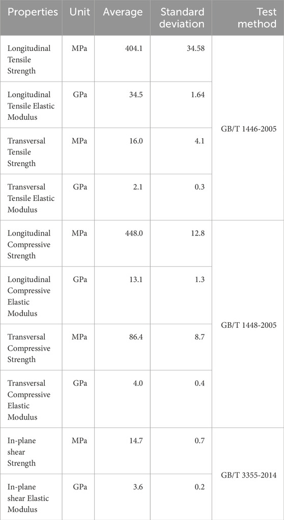
Table 1. Mechanical properties of pultruded GFRP profiles.

Table 2. Properties of the investigated hybrid beams.
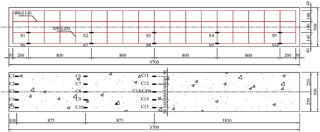
Figure 1. Details of the UHPC slab and arrangement of the strain gauges (unit: mm).

Figure 2. Details of the FRP truss (unit: mm).
Strain gauges (F1 – F20) were attached to the surface along the axial direction of each FRP truss member to record its axial strain and its locations are demonstrated in Figure 3. The deflection profile of the hybrid beam was captured by five LVDTs. Two LVDTs were mounted on the top surface of the UHPC slab along its center line at both ends to monitor the up lifting (D11 and D12 in Figure 3). Three LDVTs were installed at the center of the FRP joints of the bottom chord: two at the quarter span (D1 and D3 in Figure 3) and one at the middle span (D2 in Figure 3). The interfacial slip along the UHPC-FRP interface was recorded by seven LVDTs (D4 through D10 in Figure 3). The hybrid beam was simply supported and loaded at the mid-span via a load distributing steel plate. The loading system is a partial pressure controlled hydraulic jack with a capacity of 100-ton.
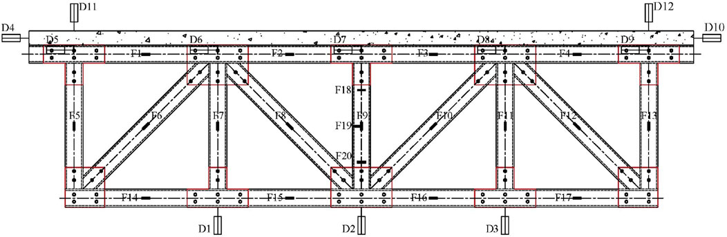
Figure 3. Arrangement of the LVDTs and strain gauges.
The fabrication process of the hybrid beam is presented in Figure 4. First, the reinforcement cage for the UHPC slab was prepared as shown in Figure 4A. It was then placed at the desired position in the wooden mold along with the top FRP chord as well as the associated shear connectors (Figure 4B). Demolding oil was applied to facilitate the demolding process as illustrated in Figure 4C. UHPC was mixed (Figure 4D) and cast (Figure 4E) into the mold. The surface was then finished (Figure 4F). Finally, the assembled FRP truss (except the top chord) was attached to the slab through the pre-installed shear connectors as shown in Figure 4G.
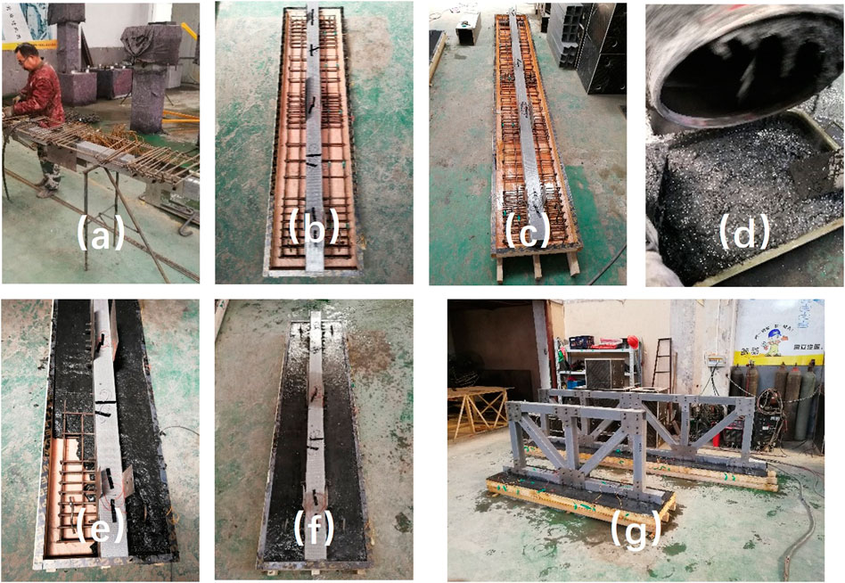
Figure 4. The process for the fabrication of the full-scale hybrid beam (A) reinforcement cage, (B) setting up the cage, (C) applying de-molding oil, (D) mixing the UHPC, (E) casting the UHPC slab, (F) finishing the surface, (G) installing the FRP truss.
3 Results and discussion
3.1 Failure characteristics of the hybrid beam
Figure 5A shows the post-test image of the hybrid beam. Typical damage characteristics were illustrated in Figure 5B–D. Cracking of the top FRP chord and the UHPC slab prior to failure were observed as shown in Figures 5B, C, respectively, implying the composite action between the UHPC slab and the FRP truss. Note that multiple micro-cracks in UHPC were observed prior to the occurrence of cracks in the web of top FRP chord. This is expected since a large portion of the compressive force was sustained by the UHPC slab and the tensile strength of UHPC is limited compared with that of FRP. In addition, the preferred longitudinal cracking in the web (Figure 5B) instead of the catastrophic flange-web fracture of FRP profile was observed. These characteristics are consistent with the pseudo ductile load-deflection behavior which will be discussed in more details in section 3.2. Appreciable local buckling of the steel UGP at the bottom chord of one end was observed (Figure 5D). In contrast, only slight buckling occurred of the steel UGP of the FRP joint along the top chord of the girder as shown in Figure 5E. It confirms the beneficial effect of the UHPC slab which improved the stiffness and alleviated the potential buckling of FRP. Note that local buckling at the bottom chord may negatively affect the load-carrying capacity and deflection of the hybrid beam. Mechanical insert as suggested by Hizam et al. can be used to solve this issue which can further improve the overall performance of the hybrid beam (Hizam et al., 2019).
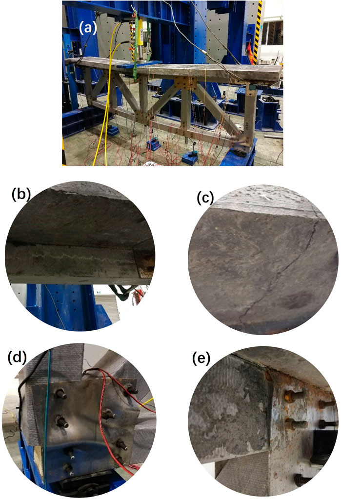
Figure 5. Typical failure characteristics of the hybrid beam subjected to three-point bending (A) image of the hybrid beam after test, (B) crack of the web of the top FRP chord, (C) crack of the UHPC slab, (D) appreciable buckling of the steel UGP, (E) slight buckling of the steel UGP.
3.2 Load-deflection behavior
Figure 6 depicts the change of deflection with the applied load for the bottom FRP chord. It can be seen that the load-deflection behavior is generally linear elastic up to a high load level of approximately 150 kN. The stiffness is then degraded as indicated by a clear reduction in the slope of the load-deflection curve. For the same applied load, the deflection at the mid-span (D2 in Figure 3) is systematically larger than that at the quarter-span (D1 and D3 in Figure 3). In contrast to the brittle failure of all-FRP composite beam, the proposed hybrid beam demonstrated a pseudo ductile behavior as indicated by a plateau after the peak load. A substantial part of the load-carrying capacity was maintained. The pronounced post peak load-carrying capacity could be attributed to: 1) the very high compressive strength and elastic modulus of the UHPC slab which could sustain a significant portion of the compressive load and restrain the deformation prior to failure; 2) the ductile behavior of UHPC under tension; 3) the FRP truss girder which ensures that each member is subjected to axial loading. This is critical to prevent the premature failure resulted from the limited transverse properties of FRP; 4) the improved performance of the novel FRP joint which ensures that the FRP truss can act synergistically with the UHPC slab; 5) the composite action between the UHPC slab and the FRP truss girder.

Figure 6. Load-deflection behavior of the hybrid beam.
Figure 7 illustrates the deflection profile along the length of the bottom chord of the FRP truss. The deflection peaks at the mid-span and is symmetric along the length of the bottom chord. Since a large portion of the applied load was transmitted to the vertical FRP member based on the recorded strain (detailed discussion is provided in section 3.4), larger deflection at mid-span was expected. The symmetric nature of the structure explains the observed symmetrical deflection. Note that the pronounced mid-span deflection can be reduced by forming a space truss configuration with two parallel panel trusses transversely connected (Smith et al., 1998). Due to the use of unified cross section, the fabrication, assembly, and installation of such joint are convenient. It can be easily expanded to form a space truss which can further improve the load-carrying capacity and reduce the deflection of the hybrid beam.
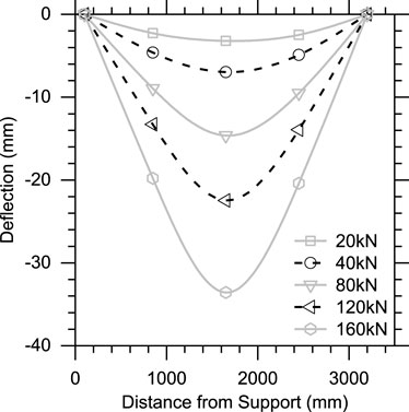
Figure 7. Distribution of the deflection along the bottom FRP chord.
3.3 Interface slip between the UHPC slab and the FRP truss
How to ensure a full composite action between the UHPC slab and the FRP truss is essential to achieve the desired performance of the hybrid beam. Therefore, the interfacial slip along the length of the hybrid beam was recorded as shown in Figure 8. The positive and negative signs are used to differentiate between the two opposite directions of the horizontal interfacial slip. It can be seen that the interfacial slip at various locations is basically negligible which is generally smaller than 1.5 mm indicating the excellent performance of the tailored UHPC-FRP shear connector. This is consistent with the push-out test results reported in (Zhong et al., 2023). The maximum interfacial slip of approximately 1.5 mm (D6 and D8) occurred between the mid-span and two ends at a high load level of 160 kN. This level of load is very close to the ultimate load of 179 kN when the flexural test was terminated due to safety concern. No interfacial slip was measured at the mid-span (D7) due to the symmetric nature of the hybrid beam and the fact that the external load was applied at this location. The noticeable interfacial slip at D4 and D5 was attributable to the local damage occurred at the other end joint connecting the FRP members F12, F13 and F17 (see Figures 3, 5D). Such localized damage could induce sudden uplift of the opposite ends which explains the appreciable interface slip at D8 and D9 (Figure 3). This is confirmed by the strains in the related FRP members which will be discussed in section 3.4.
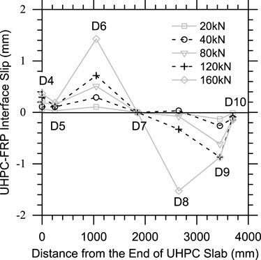
Figure 8. Interfacial slip profile.
3.4 Strain in the UHPC slab and the FRP truss
The strain of the FRP members as well as the UHPC slab is assessed to better understand the failure mechanism and synergistic effect among the two different components. Figure 9 exhibits the development of the strain with the applied load in the steel reinforcement and the matrix of the UHPC slab. The strain in the steel reinforcement at the mid-span exceeded the tensile yield strain of 2000 με (Figure 9A) while the UHPC matrix in the compression zone did not reach its compressive strain capacity of 3000 με (Figure 9B). It indicates that there is still potential to reduce the dimensions of the UHPC slab which can further reduce the weight and cost, and achieve efficient material utilization.
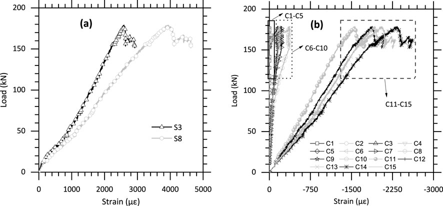
Figure 9. Strain in (A) Steel reinforcement, and (B) UHPC matrix.
The evolution of the strain of various FRP truss members is plotted in Figure 10. As can be seen from Figure 10A, the two horizontal FRP members at the middle of the top chord (F2 and F3 in Figure 3) exhibited tensile strain and those at the two ends (F1 and F4 in Figure 3) experienced compressive strain, both of which are smaller than the corresponding yield strain of FRP material (1% for tension and 4.5% for compression). All horizontal FRP members of the bottom chord (F14-17 in Figure 3) underwent tensile strain as shown in Figure 10B. Note that the strain of the FRP profiles remains significantly smaller than the corresponding yield strain of FRP material. The design of the hybrid beam is still dictated by the deflection. The tensile strain of F15 and F16 is almost identical attributing to the symmetrical configuration of the FRP truss. The strains attained are close to the tensile yield strain which indicates efficient material utilization. In contrast, for the two horizontal FRP members at the edges (F14 and F17 in Figure 3), the tensile strains deviate significantly from each other. The substantially larger tensile strain of F14 is resulted from the local buckling failure at the end joint connecting F12, F13 and F17 (Figure 5D). Increasing the thickness of the steel UGP or add mechanical inserts to the bottom end chord may be able to prevent such local damage and comparable strain of F14 and F17 can then be expected. The load path is skewed to that end leading to remarkable compressive strain in the diagonal member F12 as shown in Figure 10C. In general, the vertical members are subjected to compression with the one at the mid-span (F9 in Figure 3) experienced the highest compressive strain. This is expected since a pronounced portion of the applied load is transmitted through the vertical members at the mid-span. The slight tension in the vertical member (F5 in Figure 3) is again induced by the local damage occurred at the corner joint connecting F12, F13 and F17.
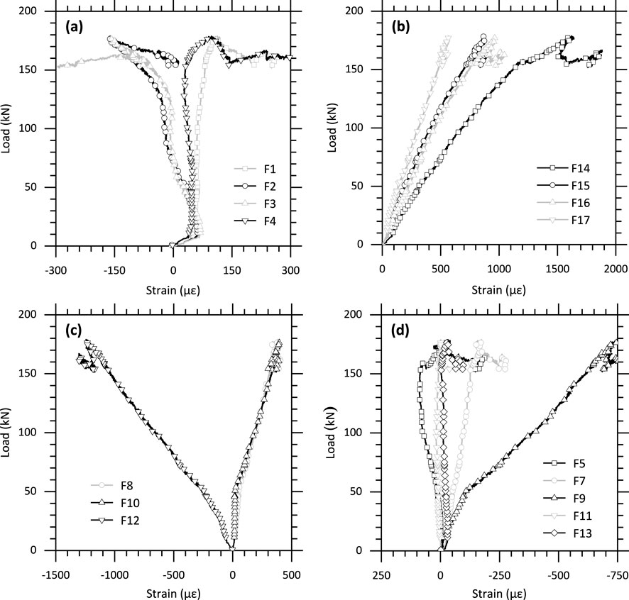
Figure 10. The strain of FRP profiles (A) top chord, (B) bottom chord, (C) diagonal member, (D) vertical member.
3.5 Comparison with the performance of other reported hybrid beams
To better understand the flexural behavior of the proposed UHPC-TFRP-HB, comparison was made with the flexural behavior of two recently reported concrete slab–FRP girder hybrid beams. One adopted NC slab while the other used UHPC slab and both of which employed I–profile as the girder. The load-deflection behavior of the proposed hybrid beam along with the NC slab - I-profile FRP girder hybrid beams subjected to three-point bending were plotted in Figure 11 (Koaik et al., 2017). The details of the two types of hybrid beams, including the properties and dimensions of the UHPC slabs and FRP girders and the corresponding shear connectors, are summarized in Table 2.
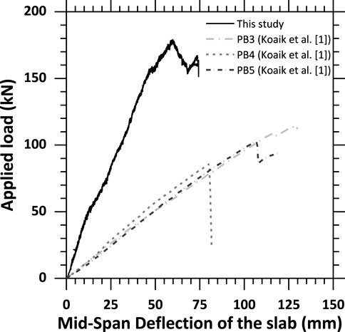
Figure 11. Load-deflection behavior of the hybrid beams under three-point bending.
It can be seen from Table 3 that the dimensions and properties of the UHPC slab and FRP girders are comparable. However, the load-carrying capacity of the proposed hybrid beam is 60–108% higher than the NC slab - I-profile FRP girder hybrid beams, irrespective the type of shear connector. In addition, the middle span deflection of the proposed hybrid beam (59 mm) is significantly smaller than that of the NC slab - I-profile FRP girder hybrid beams (80–130 mm). A substantially higher portion of the compression could be carried by the UHPC slab than the NC slab which could prevent the compressive failure of the FRP due to its significantly lower compressive strength compared with tensile strength. The robust FRP joint along with the full composite action derived from the tailored shear connector is another explanation for the superior overall performance (Zou et al., 2023; Zhong et al., 2023). In contrast to the catastrophic brittle failure without warning of the NC slab - I-profile FRP girder hybrid beams, a pseudo-ductile failure of the proposed hybrid beam was observed as indicated by the pronounced load sustained and appreciable deflection after the peak load.
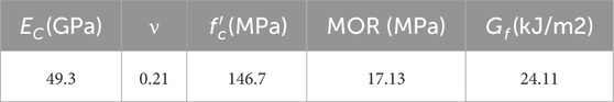
Table 3. Properties of UHPC.
Another hybrid beam evaluated is a UHPC slab–I-profile FRP girder hybrid beam (UHPC-IFRP-HB) reported in (Zhang et al., 2021). However, it is connected through steel bolts. Due to the variation in various aspects, such as the loading pattern, boundary conditions and dimensions, numerical simulation was conducted to estimate the performance of the hybrid beam proposed in this study under the same conditions as that in (Zhang et al., 2021). A finite element (FE) model was first calibrated and validated using the experimental results from this study. The load-deflection behavior under the same loading pattern and boundary conditions as that of the recently reported hybrid beam (Zhang et al., 2021) was then extracted and their behaviors were compared. Figure 12 demonstrates the simulated failure characteristics of the proposed UHPC-TFRP-HB. It can be seen that the numerically predicted features of the failure match well with the experimental observations: (1) severe buckling of the steel UGP at the support, (2) slight buckling of the steel UGP at the joint of the top FRP chord, and (3) shear failure of the web in the top chord FRP profile. The simulated load-deflection behavior is also in good agreement with the experimentally measured response as shown in Figure 13. These results indicate that the developed FE model is appropriate to predict the flexural behavior of the proposed UHPC-TFRP-HB.
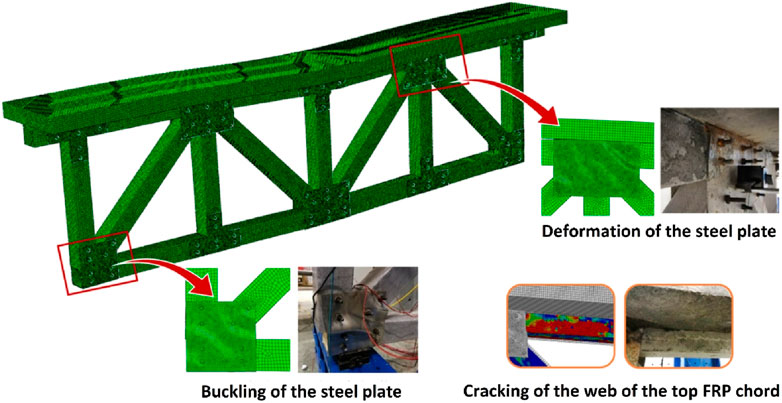
Figure 12. Comparison of the failure characteristics between the simulated and experimental results.
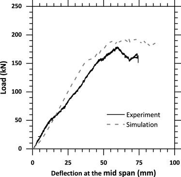
Figure 13. The simulated and experimental load-deflection behavior of the proposed UHPC-TFRP-HB.
The numerically predicted load-deflection behavior of the proposed hybrid beam was then compared with the UHPC-IFRP-HB as shown in Figure 14. The details of the two hybrid beams, including the properties and dimensions of the UHPC slabs and FRP girders and the corresponding shear connectors, are summarized in Table 3. It can be seen from Table 3 that the dimensions and properties of the UHPC slab and FRP girders are comparable. It is observed from Figure 14 that the load-carrying capacity (416 kN) of the proposed UHPC-TFRP-HB is 21% higher than that of the UHPC-IFRP-HB utilizing a I-profile FRP. In addition, the failure of the UHPC-IFRP-HB is catastrophic without any load-carrying capacity after the peak load. In contrast, the failure of the proposed hybrid beam is rather ductile which can sustain a substantial load after the peak load. The improved load-carrying capacity and ductile failure can be ascribed, at least partially, to the more robust and efficient FRP joint and shear connector as reported in previous studies (Zou et al., 2023; Zhong et al., 2023).

Figure 14. Load-deflection behavior of hybrid beams under four-point bending.
4 Conclusion
A full-scale UHPC slab–FRP truss girder hybrid beam implementing a novel FRP joint and tailored UHPC-FRP shear connector was fabricated. The flexural performance of the proposed hybrid beam in terms of the failure characteristics, load versus deflection behavior, interface slip between the UHPC slab and the FRP truss girder, and strains in different components was characterized. The behavior of the developed hybrid beam was also compared with those of two hybrid beams reported in independent studies which used NC or UHPC slab but adopted I-profile as the girder. The conclusions are summarized as follows.
(1) Typical damage features prior to failure of the full-scale UHPC-TFRP-HB when subjected to three-point bending is the cracking in the web of the top FRP chord and UHPC slab, and buckling of the steel UGP. Synergistic effect between the UHPC slab and FRP truss girder was achieved as indicated by the simultaneous cracking of both UHPC and FRP prior to ultimate failure. The UHPC slab combined with the robust shear connector was able to alleviate the damage of the top FRP chord and limit the deformation.
(2) Full composite action between the UHPC slab and the FRP truss girder was achieved when subject to flexural loading as indicated by the negligible interface slip which is generally within 1.5 mm.
(3) In contrast to the brittle failure of all-FRP beam, the hybrid beam demonstrated a pseudo-ductile behavior as indicated by the substantial portion of load-carrying capacity retained after the peak load. It can be attributed to the superior performance both at the material and structural levels. The very high compressive strength and elastic modulus of the UHPC slab could sustain a significant amount of the compressive load and restrain the deformation of the hybrid beam. The ductile behavior of UHPC under tension is also beneficial. The structural form of a truss ensured that the FRP profiles were subjected primarily to axial load which could prevent the premature failure due to the limited transverse properties of FRP. The superior FRP joint and the tailor-made shear connector ensured the composite action between the UHPC slab and the FRP truss girder which ultimately resulted in the pseudo-ductile behavior of the proposed hybrid beam.
(4) With regards to the load carrying-capacity and stiffness, the proposed UHPC-TFRP-HB outperformed the other two hybrid beams with comparable dimensions and material properties which adopted NC or UHPC for the slab but I-profile for the girder.
Data availability statement
The raw data supporting the conclusions of this article will be made available by the authors, without undue reservation.
Author contributions
JZ: Writing–original draft, Validation, Methodology. YF: Writing–original draft, Methodology, Investigation. XH: Writing–original draft, Validation, Methodology. JW: Writing–review and editing, Supervision, Project administration, Funding acquisition, Conceptualization. RZ: Writing–review and editing, Writing–original draft, Supervision, Conceptualization.
Funding
The author(s) declare that financial support was received for the research, authorship, and/or publication of this article. This research was supported by the National Natural Science Foundation of China (Project No. 52278157), China Communications Construction Group (Academician Special Project YSZX-01-2022-02-B), Southeast University Bridge Research Center (Innovation Funding Project BERC-1-1). The authors are grateful to Dr. Pu Zhang for sharing his original research data. Many thanks also go to the technicians from the structural lab of Nanjing Forestry University and Nanjing Institute of Technology for arranging the tests.
Acknowledgments
The authors are grateful to Dr. Pu Zhang for sharing his original research data. Many thanks also go to the technicians from the structural lab of Nanjing Forestry University and Nanjing Institute of Technology for arranging the tests.
Conflict of interest
Authors JZ and XH were employed by Ningbo Water Conservancy & Hydropower Planning and Design Institute Co. Ltd.
The remaining authors declare that the research was conducted in the absence of any commercial or financial relationships that could be construed as a potential conflict of interest.
Publisher’s note
All claims expressed in this article are solely those of the authors and do not necessarily represent those of their affiliated organizations, or those of the publisher, the editors and the reviewers. Any product that may be evaluated in this article, or claim that may be made by its manufacturer, is not guaranteed or endorsed by the publisher.
References
Al-Rousan, R., Issa, M., and Shabila, H. (2012). Performance of reinforced concrete slabs strengthened with different types and configurations of CFRP. Compos B Eng. 43, 510–521. doi:10.1016/j.compositesb.2011.08.050
Al-Sunna, R., Pilakoutas, K., Hajirasouliha, I., and Guadagnini, M. (2012). Deflection behaviour of FRP reinforced concrete beams and slabs: an experimental investigation. Compos B Eng. 43, 2125–2134. doi:10.1016/j.compositesb.2012.03.007
Bai, Y., and Keller, T. (2009). Shear failure of pultruded fiber-reinforced polymer composites under axial compression. J. Compos Constr. 13 (3), 234–242. doi:10.1061/(ASCE)CC.1943-5614.0000003
Bai, Y., and Yang, X. (2013). Novel joint for assembly of all-composite space truss structures: conceptual design and preliminary study. J. Compos Constr. 17 (1), 130–138. doi:10.1061/(ASCE)CC.1943-5614.0000304
Canning, L., Hollaway, L., and Thorne, A. M. (1999). An investigation of the composite action of an FRP/concrete prismatic beam. Constr. Build. Mater 13, 417–426. doi:10.1016/S0950-0618(99)00050-1
Correia, J. R., Branco, F. A., and Ferreira, J. G. (2007). Flexural behaviour of GFRP–concrete hybrid beams with interconnection slip. Compos Struct. 77 (1), 66–78. doi:10.1016/j.compstruct.2005.06.003
Deskovic, B. N., Triantafillou, T. C., and Meier, U. (1995). Innovative design of FRP combined with concrete: short-term behavior. J. Struct. Eng. 121 (7), 1069–1078. doi:10.1061/(ASCE)0733-9445(1995)121:7(1069)
El-Hacha, R., and Chen, D. (2012). Behaviour of hybrid FRP–UHPC beams subjected to static flexural loading. Compos B Eng. 43, 582–593. doi:10.1016/j.compositesb.2011.07.004
Fang, H., Bai, Y., Liu, W., Qi, Y., and Wang, J. (2019). Connections and structural applications of fibre reinforced polymer composites for civil infrastructure in aggressive environments. Compos B Eng. 164, 129–143. doi:10.1016/j.compositesb.2018.11.047
Floruţ, S. C., Sas, G., Popescu, C., and Stoian, V. (2014). Tests on reinforced concrete slabs with cut-out openings strengthened with fibre-reinforced polymers. Compos B Eng. 66, 484–493. doi:10.1016/j.compositesb.2014.06.008
Gand, A. K., Chan, T. M., and Mottram, J. T. (2013). Civil and structural engineering applications, recent trends, research and developments on pultruded fiber reinforced polymer closed sections: a review. Front. Struct. Civ. Eng. 7, 227–244. doi:10.1007/s11709-013-0216-8
Hizam, R. M., Manalo, A. C., Karunasena, W., and Bai, Y. (2018). Effect of bolt threads on the double lap joint strength of pultruded fibre reinforced polymer composite materials. Constr. Build. Mater 181, 185–198. doi:10.1016/j.conbuildmat.2018.06.061
Hizam, R. M., Manalo, A. C., Karunasena, W., and Bai, Y. (2019). Behaviour of pultruded GFRP truss system connected using through-bolt with mechanical insert. Compos B Eng. 168, 44–57. Some or all data, models, or code generated or used during this study are available from the corresponding author by reasonable request. doi:10.1016/j.compositesb.2018.12.052
Hollaway, L. C. (2010). A review of the present and future utilisation of FRP composites in the civil infrastructure with reference to their important in-service properties. Constr. Build. Mater 24 (12), 2419–2445. doi:10.1016/j.conbuildmat.2010.04.062
L. C. Hollaway, and J. G. Teng (2008). Strengthening and rehabilitation of civil infrastructures using fibre-reinforced polymer (FRP) composites (Cambridge, U.K: Woodhead Publishing Limited).
Keller, T. (2007). Use of fiber reinforced polymers in bridge construction, Structural engineering documents 7, International Association for Bridge and Structural Engineering. Zurich, Switzerland: IABSE.
Keller, T., Bai, Y., and Vallée, T. (2007). Long-term performance of a glass fiber-reinforced polymer truss bridge. J. Compos Constr. 11 (1), 99–108. doi:10.1061/(asce)1090-0268(2007)11:1(99)
Koaik, A., Bel, S., and Jurkieviez, B. (2017). Experimental and analytical model of concrete-GFRP hybrid beams under flexure. Compos Struct. 180, 192–210. doi:10.1016/j.compstruct.2017.07.059
Luo, F. J., Bai, Y., Yang, X., and Lu, Y. (2016). Bolted sleeve joints for connecting pultruded FRP tubular components. J. Compos Constr. 20 (1), 04015024. doi:10.1061/(ASCE)CC.1943-5614.0000580
Neto, ABDS, and La Rovere, H. L. (2010). Composite concrete. GFRP slabs for footbridge deck systems. Compos Struct. 92, 2554–2564. doi:10.1016/j.compstruct.2010.02.005
Seo, S. Y., Feo, L., and Hui, D. (2013). Bond strength of near surface-mounted FRP plate for retrofit of concrete structures. Compos Struct. 95, 719–727. doi:10.1016/j.compstruct.2012.08.038
Smith, S. J., Parsons, I. D., and Hjelmstad, K. F. (1998). An experimental study of the behavior of connections for pultruded GFRP-I beams and rectangular tubes. Compos Struct. 42 (3), 281–290. doi:10.1016/S0263-8223(98)00082-8
Teng, J. G., Chen, J. F., Smith, S. T., and Lam, L. (2003). Behaviour and strength of FRP-strengthened RC structures: a state-of-the-art review. Struct. Build. 156, 51–62. doi:10.1680/stbu.2003.156.1.51
Wu, C., Zhang, Z., and Bai, Y. (2016). Connections of tubular GFRP wall studs to steel beams for building construction. Compos B Eng. 95, 64–75. doi:10.1016/j.compositesb.2016.03.081
Yang, X., Bai, Y., Luo, F. J., Zhao, X., and He, X. (2017). Fiber-reinforced polymer composite members with adhesive bonded sleeve joints for space frame structures. J. Mater Civ. Eng. 29 (2), 04016208. doi:10.1061/(ASCE)MT.1943-5533.0001737
Zhang, P., Lv, X., Liu, Y., Zou, X., Li, Y., Wang, J., et al. (2021). Novel fiber reinforced polymers (FRP)-ultrahigh performance concrete (UHPC) hybrid beams with improved shear performance. Constr. Build. Mater 286, 122720. doi:10.1016/j.conbuildmat.2021.122720
Zhao, X. L., Bai, Y., Al-Mahaidi, R., and Rizkalla, S. (2014). Effect of dynamic loading and environmental conditions on the bond between CFRP and steel: state-of-the-art review. J. Compos Constr. 18 (3), A4013005. doi:10.1061/(ASCE)CC.1943-5614.0000419
Zhao, X. L., and Zhang, L. (2007). State-of-the-art review on FRP strengthened steel structures. Eng. Struct. 29, 1808–1823. doi:10.1016/j.engstruct.2006.10.006
Zhong, R., Ai, X. B., Feng, Y., Zou, X., and Wang, J. (2023). Characterization of the performance of a tailored shear connector for UHPC slab -FRP truss hybrid beam. J. Build. Eng. 72, 106576. doi:10.1016/j.jobe.2023.106576
Zhong, R., Ai, X. B., Pan, M., Yao, Y., Cheng, Z., Peng, X., et al. (2024). Durability of micro-cracked UHPC subjected to coupled freeze-thaw and chloride salt attacks. Cem. Concr. Compos 148, 105471. doi:10.1016/j.cemconcomp.2024.105471
Zhong, R., Zhang, F., Poh, L. H., Wang, S., Le, H. T. N., and Zhang, M. H. (2021). Assessing the effectiveness of UHPFRC, FRHSC and ECC against high velocity projectile impact. Cem. Concr. Compos 120, 104013. doi:10.1016/j.cemconcomp.2021.104013
Zhong, R., and Zhang, F. L. (2023). Engineering high-performance cementitious matrices for improved projectile impact resistance with silane, micro fibrillated cellulose and fine calcined bauxite aggregate. Cem. Concr. Compos 135, 104835. doi:10.1016/j.cemconcomp.2022.104835
Zhu, J. X., Weng, K. F., Huang, B. T., Xu, L. Y., and Dai, J. G. (2024). Ultra-High-Strength Engineered Cementitious Composites (UHS-ECC) panel reinforced with FRP bar/grid: development and flexural performance. Eng. Struct. 302, 117193. doi:10.1016/j.engstruct.2023.117193
Zou, A., and Keller, T. (2005). Joining techniques for fiber reinforced polymer composite bridge deck systems. Compos Struct. 69, 336–345. doi:10.1016/j.compstruct.2004.07.016
Zou, X., Feng, P., Bao, Y., Wang, J., and Xin, H. (2020). Experimental and analytical studies on shear behaviors of FRP-concrete composite sections. Eng. Struct. 215, 110649. doi:10.1016/j.engstruct.2020.110649
Zou, X., Feng, P., and Wang, J. (2016). Perforated FRP ribs for shear connecting of FRP-concrete hybrid beams/decks. Compos Struct. 152, 267–276. doi:10.1016/j.compstruct.2016.05.039
Zou, X., Feng, P., and Wang, J. (2018b). Bolted shear connection of FRP-concrete hybrid beams. J. Compos Constr. 22 (3), 04018012. doi:10.1061/(ASCE)CC.1943-5614.0000845
Zou, X., Feng, P., Wang, J., Wu, Y., and Feng, Y. (2018a). FRP stay-in-place form and shear key connection for FRP-concrete hybrid beams/decks. Compos Struct. 192, 489–499. doi:10.1016/j.compstruct.2018.03.011
Zou, X., Feng, Y., Zhong, R., Fang, T., and Wang, J. (2023). An experimental study of FRP truss side plate joint. Constr. Build. Mater 365, 130012. doi:10.1016/j.conbuildmat.2022.130012
Zou, X., Lin, H., Feng, P., Bao, Y., and Wang, J. (2021). A review on FRP-concrete hybrid sections for bridge applications. Compos Struct. 262, 113336. doi:10.1016/j.compstruct.2020.113336
Keywords: UHPC slab, FRP truss, hybrid beam, FRP joint, shear connection
Citation: Zhou J, Feng Y, Huang X, Wang J and Zhong R (2024) Flexural behavior of a UHPC slab - FRP truss hybrid beam implementing a novel FRP joint and tailored shear connector. Front. Mater. 11:1460387. doi: 10.3389/fmats.2024.1460387
Received: 06 July 2024; Accepted: 13 August 2024;
Published: 10 September 2024.
Edited by:
Bo-Tao Huang, Zhejiang University, ChinaReviewed by:
Ling-Yu Xu, Zhejiang University, ChinaJixiang Zhu, Hong Kong Polytechnic University, Hong Kong, SAR China
Copyright © 2024 Zhou, Feng, Huang, Wang and Zhong. This is an open-access article distributed under the terms of the Creative Commons Attribution License (CC BY). The use, distribution or reproduction in other forums is permitted, provided the original author(s) and the copyright owner(s) are credited and that the original publication in this journal is cited, in accordance with accepted academic practice. No use, distribution or reproduction is permitted which does not comply with these terms.
*Correspondence: Rui Zhong, cnVpLnpob25nQG1zdC5lZHU=