 Xiao Yang1
 Zhen Wang
 Qi-Hang Zhang
 Qiao-Ling Liu
- 1School of Civil Engineering, Shandong Jianzhu University, Jinan, China
- 2Engineering Research Institute of Appraisal and Strengthening of Shandong Jianzhu University Co., Ltd., Jinan, China
- 3Jinan Cigarette Factory, China Tobacco Shandong Industrial Co., Ltd., Jinan, China
- 4Key Laboratory of Building Structural Retrofitting and Underground Space Engineering of Ministry of Education, Jinan, China
This paper explored the effects of various amounts of cellulose nanocrystals (CNCs), namely 0%, 0.1%, 0.2%, and 0.4% of binder weight, on the rheology, pore structure, mechanical properties, and 3D distribution of fibers of an engineered cementitious composite (ECC). The two rheological parameters, namely the yield stress and plastic viscosity, of the matrix containing the CNCs increased. Low-field nuclear magnetic resonance (LF-NMR) analysis, as a non-destructive method, proved that the addition of the CNCs to the ECC could reduce the porosity of the material and refine its pore size distribution. The addition of the CNCs enhanced the compressive strength of the ECC by 19.6%–33%. The results from uniaxial tensile tests showed incorporating the CNCs into the matrix could enhance the initial cracking strength and ultimate tensile strength of the ECC but reduce their tensile strain-hardening capacity. The optimal addition of 0.1% CNCs could effectively offset the decrease in strength due to increasing FA content, and maintain a relatively high level of tensile strain capacity of over 3%. Finally, X-ray micro-computed tomography (micro-CT) with ORS Dragonfly software was employed to reconstruct 3D images of the ECC to present the improvement in the fiber distribution due to the addition of the CNCs.
1 Introduction
Engineered cementitious composites (ECC) are a specific category of fiber-reinforced cementitious composites with high tensile strain capacity (Li, 2019). By incorporating about 2% volume dosage of polyvinyl alcohol (PVA) or polyethylene (PE) short-fibers, ECC exhibits a tensile strain-hardening behavior with the ultimate tensile strain of exceeding 2%, multiple cracking characteristics, high deformation capacity, and so forth. ECC has been developing rapidly in numerous fields due to its excellent deformation capacity, high toughness, and good energy dissipation capacity.
Since the invention of PVA-ECC, they have been continuously modified and improved through, for instance, improving the surface treatment of PVA fibers and the properties of the matrix. Various types of modifying agents were applied to the surface treatment of PVA fibers to reduce the chemical bonding significantly and thus provide higher tensile ductility (Arain et al., 2019; Ding et al., 2019). Compared with the modification of the surface of fibers, the treatment of the matrix would be easier to achieve. For example, incorporating high volumes of fly ash (Yang et al., 2007) and some particles with low bonding to the cementitious matrix (Wang and Li, 2004; Pang et al., 2014) into the matrix of an ECC could improve its ductility. Ma et al. (2017) and Pan et al. (2018) improved the compressive strength and tensile strain-hardening behavior of an ECC by incorporating an optimal content of CaCO3 whisker and PVA fibers, greatly reducing the cost of production. The microstructural images in their work confirmed that embedding CaCO3 whiskers in the matrix inhibited the initiation and propagation of microscopic cracks, and PVA fibers prevented macroscopic cracks.
In recent years, applying nanomaterials to cementitious composites has increasingly been a popular topic. Adding nano-particles, including multi-walled carbon nanotubes (MWCNTs) (Xu et al., 2019), graphene oxide (GO) (Lu et al., 2016), nano-SiO2 (NS) (Li et al., 2016; Xi et al., 2020), and nano-CaCO3 (NC) (Ding et al., 2020), has proved to be an effective method for improving the properties of, for instance, high ductility cementitious composites. Further, these nanoparticles could act as nucleation sites and thus accelerate the hydration rate, which produces more hydrated calcium silicate gels to fill the micro-pores of the matrix and hence refines its pore size distribution. The interface between the matrix and fibers could be improved by the addition of nanoparticles, thereby modifying the microscopic properties of the matrix and improving its mechanical properties.
Cellulose stands as the most plentiful among all renewable and biodegradable natural resources. Many methods have been developed for producing nanocellulose from natural cellulose materials, which is in accord with the concept of green development. Nanocellulose materials mainly consist of cellulose nanofibrils (CNF), cellulose nanocrystal (CNC), and bacterial nanocellulose (BNC). Cellulose nanocrystals (CNCs) which are rod-like and whisker-shaped nanoparticles with a length of several microns and a diameter of 5–50 nm can be extracted from plants, woods, etc. on a nanoscale. Compared with macroscale fibers, CNCs have a number of unique features such as a high aspect ratio, low density (1.3 g/m3), a high elastic modulus, and high crystallinity (54%–88%). However, there are few studies on the effect of CNCs on cementitious materials. Some works have investigated the influence of CNCs on the mechanical and microscopic properties of cement paste. CNCs exert an effect on accelerating the hydration reactions of cement, their nucleation effect has been also verified (Zheng et al., 2023). According to the short circuit diffusion, CNCs can adhere to the surface of cement particles, and act as a transmission path, carrying curing water to unhydrated cement because of their hydrophilicity (Cao et al., 2016). Cao et al. (2015) found that an ideal CNC dosage could enhance the cement hydration degree and the strength development of cement paste; they also investigated the influence of CNCs on the rheology of the cement paste. Moreover, CNCs could hold cement paste from cracking under a low-temperature environment (Liu et al., 2019).
Across the existing studies, no research has been reported on the application of CNCs in ECC yet. This paper preliminarily studies the effect of CNCs on the properties of ECC through rheological analysis, uniaxial direct tensile test, and compressive strength evaluation. On a microscale, the effect of the CNCs on the distribution of PVA fibers in the ECC was studied by X-ray micro-computed tomography (micro-CT) and 3D reconstruction of the captured slices of the samples. Moreover, the porosity tests were conducted using the low-field nuclear magnetic resonance (LF-NMR) method to evaluate the influence of the CNCs on the pore size distribution of the ECC.
2 Materials and methods
2.1 Materials
The materials used in all the mixtures were ordinary 42.5 Portland cement, fly ash, and quartz sand (with a particle size of 120–212 μm). Table 1 lists the chemical compositions of the cement and fly ash. Moreover, a proper high-range water-reducing admixture (HRWRA) was employed to maintain an appropriate flowability of the mixtures. The polyvinyl alcohol (PVA) fibers (KURALON K-Ⅱ) used in all the mixtures were also supplied by the Japanese Kuraray Company, and they possessed a diameter of 40 μm, a length of 12 mm, and a density of 1,300 kg/m3. The mixture proportions adopted are listed in Table 2.
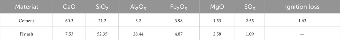
Table 1. Chemical compositions of the cement and fly ash (wt%).
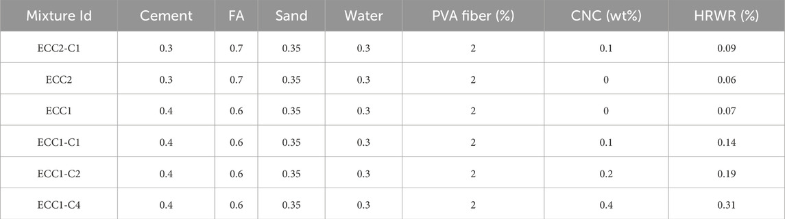
Table 2. Mixture proportions.
The CNCs used in this research were supplied by Qihong Company of Technology, Guilin, China in the form of suspensions with a weight content of 9.3%; it was extracted from waste paper pulp through the TEMPO oxidation method. Figure 1 shows the features of CNCs. CNCs had a diameter of 10–50 nm and a length of 100–1,000 nm. From the Fourier transform infrared (FT-IR) spectra of CNCs, the peaks at 3,340 and 1,600 cm−1 were associated with -OH (from hydroxyl group) and -COO− (from carboxylic salt), respectively.

Figure 1. Features of CNCs: (A) SEM image and (B) FT-IR.
The CNCs were added to the matrix at different amounts of 0%, 0.1%, 0.2%, and 0.4% of the total weight of the binder. In order to more uniformly disperse the CNC suspensions in the mortar, they must be homogenized in advance by magnetic stirring and ultrasonic dispersion in water [21].
2.2 Mixing procedure
A mortar mixer with a capacity of 15 L was used. All the dry raw materials including the cement, fly ash, and quartz sand were dry mixed for 2 min. Subsequently, water and the admixtures, including the CNC suspensions and HRWRA, were added and mixed for another 6 min to ensure the homogeneity of the fresh mortar. To ensure the workability of the ECC, the fluidity of all the mixtures, measured by the reciprocating flow table method, should reach nearly the same value of about 180–200 mm by adjusting the content of the HRWRA, and no bleeding phenomenon should be seen in all the mixture proportions. Finally, the PVA fibers were added slowly and stirred quickly for 2 min until achieving uniform dispersion. The fresh mixture was cast into molds and demolded after curing for 24 h. Then, all the specimens were cured in a air curing room at a relative humidity of more than 60% and a temperature of 20°C ± 2°C for 28 days before testing.
2.3 Testing methods
2.3.1 Rheology
The fresh mortar with different amounts of the CNCs was immediately transferred to a container for rheological analysis before adding the PVA fibers, and all tests were performed after 10 min of adding water. A rotary rheometer (Kinexus, Malvern, United Kingdom) was utilized to measure the rheological properties of the mortar at a steady shear rate (see Figure 2). Figure 2B delineates the rheological test program, which mainly includes two stages of pre-shearing and data-logging (Keskinateş and Felekoğlu, 2018). In the pre-shearing stage, the shear rate was increased from 0 to 25 s−1 within 30 s and then decreased to 0 s−1 within 30 s. The purpose of pre-shearing is to make each group of the mortar have the same initial shearing state during the rheological analysis. In the data-logging stage, after completion of the pre-shearing step, and waiting for 30 s, the shear rate was increased from 0 to 50 s−1 within 60 s and then dropped to 0 within 60 s. A total of 120 data points were collected to draw the shear rate–shear stress curve.
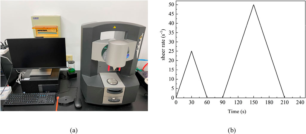
Figure 2. Rheology test: (A) setup and (B) program.
2.3.2 Pore structure
LF-NMR as a non-destructive technology was employed to measure the pore size distribution of the specimens (Wang et al., 2020). The cylindrical samples with a diameter and a length of 50 mm were used. First, the connected pores of the specimens were saturated with water. Then, the signal intensity of the hydrogen protons of water was recorded and converted to the porosity and pore size distribution of the specimens by LF-NMR. The LF-NMR instrument (MacroMR12-150H-I, Suzhou Niumag Analytical Instrument Corporation, Jiangsu, China) employed had a resonance frequency of 12.75 MHz and a radio frequency (RF) coil of 110 mm.
2.3.3 Uniaxial direct tensile test
The uniaxial direct tensile test adopted a type of dog-bone specimen (see Figure 3) to measure the tensile stress-strain curves. At least four specimens were prepared for every mixture proportion. All the tests were conducted using a 600 kN microcomputer-controlled hydraulic servo test machine at a constant-velocity displacement of 0.5 mm/min, and the variation in the tensile length of the middle-cross-section was measured with an electronic extensometer in a gauge length of 100 mm.
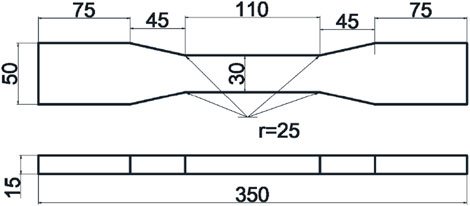
Figure 3. The dog-bone specimen for tensile tests (all the dimensions are in mm).
2.3.4 Compressive strength test
Three cube specimens with the dimensions 70.7 mm × 70.7 mm × 70.7 mm were prepared to measure the compressive strength after 28 days of curing. A 3,000 kN microcomputer-controlled hydraulic servo test machine was employed to measure the compressive strength of the samples at a stress control of 0.6 MPa/s.
2.3.5 Fiber distribution
In the fiber distribution analysis, to avoid error in the sides of the specimens, cylinders with a diameter of 10 mm and a height of 10 mm were cored from the specimens cured for 28 days by water jet saw, as shown in Figure 4. Then, the samples were scanned by X-ray computed tomography using Zeiss Xradia 510 Versa, Germany. The voltage and current of the X-ray tubes were 80 kV and 87 μA, respectively. A total of 819 2D slices with an image size of 1,000 × 1,024 pixels were obtained, and ORS Dragonfly software was utilized for processing the 2D slices of the samples to obtain the 3D reconstruction images.
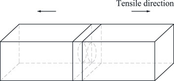
Figure 4. The location of the core extracted from the composites.
3 Results and discussion
3.1 Rheology
The tensile strain-hardening behavior of ECC is closely related to the uniformity of fiber dispersion, and excellent mechanical properties could be obtained by achieving uniform fiber dispersion within a reasonable range (Sahmaran et al., 2013). Poor fiber dispersion will result in a reduced effective fiber volume fraction, which forms sections with weak bridging capacity, thereby leading to a lower tensile strain capacity (Li and Li, 2013). Since various measurement methods can produce a different result, an optimal range of mortar (without fiber) viscosity should be found for reaching uniform fiber dispersion.
Both shear rate-shear stress upward and downward curves can be obtained by matrix rheology tests. Herein, the rheological downward curves are selected for analysis. Since the uniformity of the mortar was ensured by its shear behavior at a higher shear rate before reaching the given rate, the data obtained from the downward curves are more reliable and repeatable (Cappellari et al., 2013). The rheological downward curves of the samples are presented in Figure 5. After regression analysis by Origin software (OriginLab Corporation), the rheological curve of each group conforms to the modified Bingham model equation (
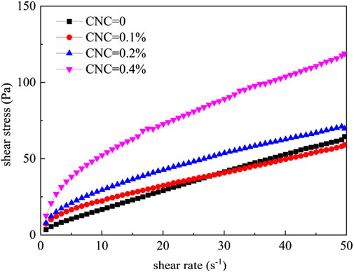
Figure 5. Rheological curves at different amounts of the CNCs.
According to the regression formulas and rheological parameters of the modified Bingham plastic model listed in Table 3, the fitting correlation coefficients of the rheological curves of the mixtures in each group are 0.99, showing a high correlation, which proves that the modified Bingham plastic model accurately fits the experimental data.
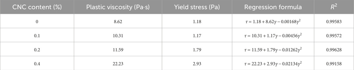
Table 3. Rheological parameters of each group of the specimens.
Figure 6 displays the trends of yield stress and plastic viscosity of the cementitious composite matrix with the CNC content. As mentioned in Section 2.1, the HRWRA was used to maintain the flowability of the fresh mortar. In fact, incorporating the HRWRA into the cement could break down the cement flocculation structure to release free water, thereby improving the flowability, and thus reducing the yield stress and plastic viscosity, of the fresh mortar. Considering the interaction influence of both the HRWARA and CNC, it still can be seen that the addition of the CNCs has an impact on yield stress and plastic viscosity.
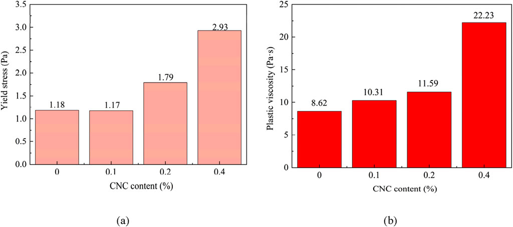
Figure 6. Variation of (A) yield stress and (B) plastic viscosity of the fresh matrix with the CNC content.
The yield stress, which is produced by the absorption and friction between particles inside the mixture, is the minimum shear stress which causes the mortar to flow and undergo deformation. The variation of the yield stress measured in a fresh state of the mortar with the CNC content is delineated in Figure 6A; generally, the yield stress increased steadily as the CNC content rose. When the CNCs were added, the water requirement of the fresh mortar obviously increased in the process of stirring. Then, the HRWRA was needed to improve the flowability of the mortar. There is an exception to the trend of the effect of the CNCs on the yield stress of the mortar; indeed, the yield stress of the mortar containing 0.1% of the CNCs is slightly lower than that of the mortar without the CNCs, which might indicate that the effect of the corresponding content of the HRWRA is slightly stronger than that of the CNCs. Nonetheless, because of the satisfaction of the workability and flowability, this result is considered to be reasonable. The mechanism of the CNCs appears to be similar to that of viscosity-enhancing admixtures based on cellulose ether, the role of which is to increase the viscosity of cementitious composites. On the one hand, CNCs are rod-like and whisker-shaped particles, so the specific surface area of them is higher than that of most of nano-particles. Moreover, CNCs provide for surface distinctive chemistries because of hydroxyl groups on their surface; in fact, the hydroxyl groups on the surface of CNCs are generally regarded as the initial sites of water sorption. Therefore, the surface of CNCs can absorb plenty of water and reduce the effective water used for stirring mixtures, resulting in an increase in the friction between particles inside the mixtures. However, another possible explanation for water absorption is that the absorbed water is insignificant and considered to be negligible compared to the total mixing water (Cao et al., 2015). Hence, the effect of water absorption into CNCs could be neglected when discussing the rheology of the fresh mortar. A higher CNC content (0.4%) gave rise to a very high yield stress, which was attributed to the agglomeration of the CNCs. On the other hand, CNCs as nanowhiskers could fill smaller spaces between other particles, and thus increase the probability of collision between particles during rotating (Jiang et al., 2018). Meanwhile, CNCs could retard the cement reactions by adhering to the cement particles and reducing the reaction surface area between the cement and water (Cao et al., 2015), which was also consistent with the practical phenomenon. Additionally, Francisco Montes (Montes et al., 2020) found that, at a lower content (smaller than 0.2 vol% relative to dry cement, which is equivalent to about 0.1 wt% relative to dry cement), CNCs act as water reducers to improve the flowability of the cement paste by decreasing its yield stress, which could be attributed to the steric stabilization reducing the positive-negative interactions between the hydration products; their results also confirmed that the performance of the CNCs was similar to a viscosity-enhancing admixture.
The plastic viscosity parameter denoting the ability to resist the flow inside the fresh mortar is related to the shape, size, and concentration of the mixing particles. The plastic viscosity increased steadily with the addition of the CNCs in Figure 6B. It should be noted that this result also depended on the special characteristics of the CNCs. As previously mentioned, CNCs could absorb free water, fill smaller spaces between particles, and agglomerate, so they could raise the flow resistance. It could be observed that when the CNC content was higher than 0.2%, the agglomeration of the CNCs was likely to further increase the yield stress of the mortar, and a larger force was required for breaking down the agglomerate. Furthermore, the amount of air entrapped in the mortar increased with a rise in the CNC content, which could lead to enhancing the growth rate of viscosity (Struble and Jiang, 2004).
3.2 Pore structure
Pore distribution is of great importance in improving the mechanical properties and durability of cementitious composites. The addition of nanoparticles is considered to be an effective method for enhancing the pore structure of cementitious composites (Ghafari et al., 2015). Pores are classified on the basis of the pore radius (Kumar and Bhattacharjee, 2003) as gel pores (0.5 nm < radius <10 nm), fine capillary pores (10–50 nm), large capillary pores (50–5,000 nm), and non-capillary pores (radius >5,000 nm).
The pore size distribution and pore volume distribution of the prepared specimens at different amounts of the CNCs, namely 0%, 0.2%, and 0.4%, are plotted in Figure 7. It can be inferred from Figure 7A that the values for the total porosity of the composites containing 0%, 0.2%, and 0.4% of the CNCs were 8.707%, 6.439%, and 6.274% respectively, which represented the area enclosed by the pore size distribution curves. When the content of the CNCs increased from 0% to 0.4%, the total porosity of the specimens kept decreasing, and the pore size distribution was also refined. Also, the peak of the pore size distribution curve moved to the left, which indicated that the most probable pore size dropped with an increase in the CNC content. The most probable pore size was around 10 nm and corresponded to a critical position between gel pores and fine capillary pores at a CNC content of 0%. However, the most probable pore size at a CNC content of 0.2% and 0.4% was around 7 nm and 6 nm respectively, both corresponding to gel pores; it is obvious that the most probable pore size decreased as the CNC content of the composites increased.
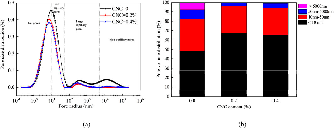
Figure 7. Variation of (A) pore size distribution and (B) pore volume distribution of the engineered cementitious composites with the CNC content.
Figure 7B illustrates the pore volume distribution of three specimens divided into four types. As the CNC content increased from 0% to 0.4%, various pores were refined. At a CNC content of 0.2%, the total volume of the gel pores and fine capillary pores was the maximum compared with the two other groups. Moreover, these results indicated that the addition of the CNCs refined the microstructure of the ECC and improved its compactness.
3.3 Compressive strength
The variation of the average compressive strength of all the specimens cured for 28 days with the CNC content is presented in Figure 8. The compressive strength of the ECC1 without CNCs was 49.6 MPa, and the addition of the CNCs significantly enhanced the compressive strength of the ECC1. When 0.1%, 0.2%, and 0.4% of the CNCs were added, the average compressive strength of the ECC was respectively 59.3, 62.8, and 66.0 MPa, indicating an increase of 19.6%, 26.6%, and 33% respectively. The improvement in the compressive strength might be attributed to CNCs accelerating the cement hydration and filling the smaller spaces, as proved in Section 3.2. The porosity of the specimens decreased at a higher CNC content, which increased the compactness of the matrix and then enhanced its compressive strength. Although the average compressive strength increased steadily with the CNC content, the rate of increase in the compressive strength fell relatively at higher amounts of the CNCs. We could speculate that when the CNC content was higher than 0.2%, the CNCs could easily agglomerate, thereby influencing the uniform dispersion of the PVA fibers and leading to a smaller rate of increase in the compressive strength of ECC1. Additionally, a higher replacement of OPC by FA reduced the compressive strength of ECC2 due to a decreasing cement hydration degree. Further, incorporating 0.1% CNCs obtained a compressive strength of 47 MPa with a 23.7% enhancement compared to ECC2. The compressive strength of ECC2-C1 was slightly lower than that of ECC1.
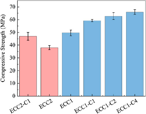
Figure 8. Variation of the average compressive strength of the ECC with different the CNC content.
3.4 Uniaxial tensile behavior
The uniaxial tensile stress-strain curves of all the specimens at various amounts of the CNCs are delineated in Figure 9. The initial cracking strength, the ultimate tensile strength, and the tensile strain were used to characterize the tensile behavior capacity of the ECC. As tabulated in Table 4, the average initial cracking strength at a CNC content of 0%, 0.1%, 0.2%, and 0.4% was 3.6, 4.6, 4.9, and 5.1 MPa respectively; obviously, the average initial cracking strength of the composites increased significantly with the addition of the CNCs. Compared with the blank group, the average initial cracking strength of the ECC containing 0.1%, 0.2%, and 0.4% of the CNCs increased by 28%, 36%, and 41% respectively. The initial cracking strength of the ECC is mainly determined by the matrix. The rise in the initial cracking strength could be attributed to the increase in the compactness, and the role of the CNCs with whisker-shaped particles in bridging the initial flaws of the matrix at a microscopic level.
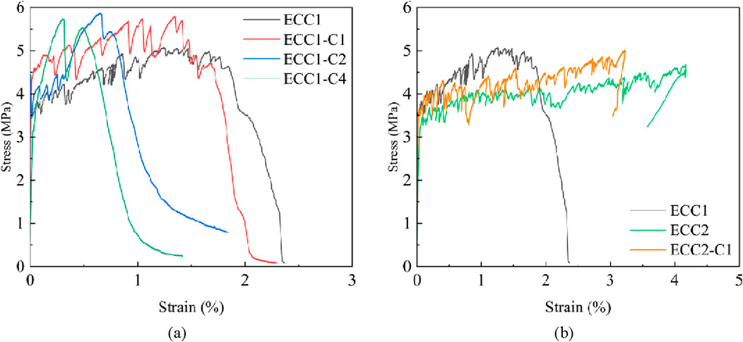
Figure 9. Tensile stress-strain curves of all the specimens at different amounts of the CNCs: (A) ECC1 series; (B) ECC2 series.
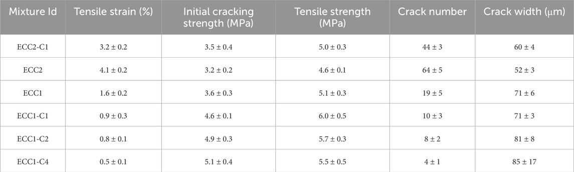
Table 4. Tensile parameters of all the specimens.
Table 4 also compares the average ultimate tensile strength of all the specimens. It can be noticed that the trend of the variation in the average ultimate tensile strength was similar to that of the initial cracking strength. However, the enhancement of the initial cracking strength was more obvious, and the ultimate tensile strength improved by only 20%, 14.3%, and 8.6% respectively at a CNC content of 0.1%, 0.2%, and 0.4%. The fiber bridging capacity that depends on the frictional bonding strength governs this value. Meanwhile, the frictional bonding strength is determined by the interface between the matrix and fibers. Adding the CNCs might form stronger frictional bonding between the matrix and fibers, which could further increase the ultimate tensile strength of the ECC. Moreover, higher concentrations of the CNCs would lead to the non-uniform dispersion of the fibers, resulting in a lesser enhancement of the ultimate tensile strength of the ECC.
The tensile strain capacity is considered to be the most important index of ECCs. Under uniaxial tensile conditions, all the specimens presented a strain-hardening behavior to varying degrees, which was caused by the cracking of the matrix, the propagation of cracks, and the debonding and rupture processes of the fibers. With an increase in the CNC content, the tensile strain-hardening capacity dropped continuously from 1.6% to 0.5%. In the microscopic design of pseudo-strain hardening, an energy criterion should be satisfied to ensure a cracking mode, as expressed in Equation 1:
where
Although adding more FA reduced the tensile strength of ECC2, the tensile strain capacity significantly enhanced to 4.1%, and the crack width decreased. This is due to a dropping chemical bond between fiber and matrix with the increasing FA content (Yang et al., 2007). Compared to ECC1, ECC2-C1 achieved a comparable value of initial cracking strength and tensile strength as 0.1% CNCs were incorporated. Specifically, the tensile strain capacity of ECC2-C1 was nearly two times that of ECC1, and ECC2-C1 possessed a tighter crack width than ECC1, which was conducive to self-healing capacity and durability.
3.5 Fiber dispersion
To obtain the internal characteristics of the fiber distribution, the fibers were reconstructed and extracted by utilizing ORS Dragonfly software. X-CT micro-computed tomography can identify different materials based on their density and provide a gray-scale presentation in which the greater the density is, the higher the gray scale is. All the fibers regarded as the regions of interest (ROI) should be separated from the matrix by threshold segmentation. It should be noted that the density of the PVA fibers was close to the other components, so an initial threshold segmentation might include much unwanted noise. ORS Dragonfly software provides a deep learning tool based on artificial intelligence (AI) to denoise and enhance images, improving the precision of segmentation. The deep learning steps were as follows:
a. Selecting 10 serial 2D slices with distinct fiber characteristics from all the 2D slices.
b. Marking accurately all the fibers as ROI in these 10 slices by an ROI painter tool.
c. Using the deep learning tool and training the data of these 2D slices for creating a specific deep learning model.
d. Applying the model to all the 2D slices and checking the accuracy of the result.
e. Adjusting some parameters influencing the accuracy of the deep learning and choosing the best optimal parameter.
It should be noted that due to the limited number of slices used to perform the deep learning, the data perpendicular to the XY plane slices could not be correctly identified. Therefore, we must extract the ROI in the XY, XZ, and YZ planes respectively, and then unite the three ROI.
Figures 10–12 present the ROI segmentation and 3D reconstruction of the composites having 0%, 0.2%, and 0.4% of the CNCs respectively. It can be seen in Figures 10C, 11C, 12C that the distribution of fibers in the matrix was not uniform in the 3D images. During pouring the fresh material into the mold, we ensured that the fresh materials freely flowed into the models as much as possible, so the fibers were more likely to be parallel to the tensile direction. Comparing the fiber 3D reconstruction images reveals that the fibers of the composites with 0.2% and 0.4% of the CNCs tended more to be parallel to the tensile direction. Highly inclined fibers usually tend to reduce their ability to bridge cracks (Tosun-Felekoǧlu et al., 2014). A proper content of the CNCs increased the yield stress and plastic viscosity of the matrix, which could help to break down the agglomerate of the PVA fibers, so fibers could be well dispersed. However, at a CNC content higher than 0.2%, the addition of the CNCs gave rise to too high yield stress and plastic viscosity of the matrix, which might impose a negative impact on the dispersion of the PVA fibers. The probability of the appearance of weakest cross-sections might be higher at either too high or too low fiber volume fractions in local sections, which decreased the ductility of the ECC.
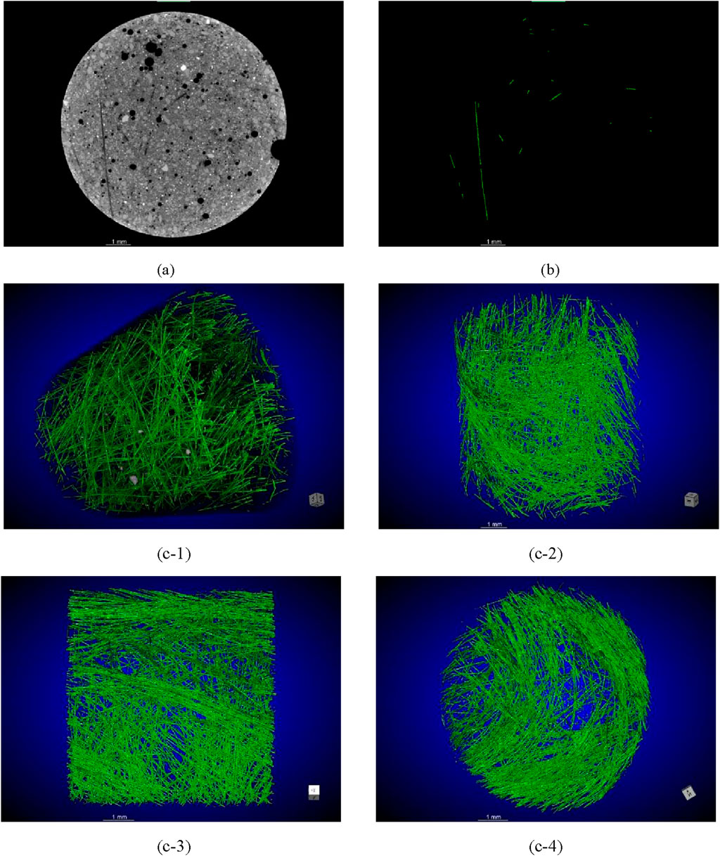
Figure 10. ROI segmentation and 3D reconstruction of the ECC without CNCs: (A) original 2D slice image; (B) ROI segmentation by the deep learning model; (C) 3D reconstruction of the fibers at different angles.
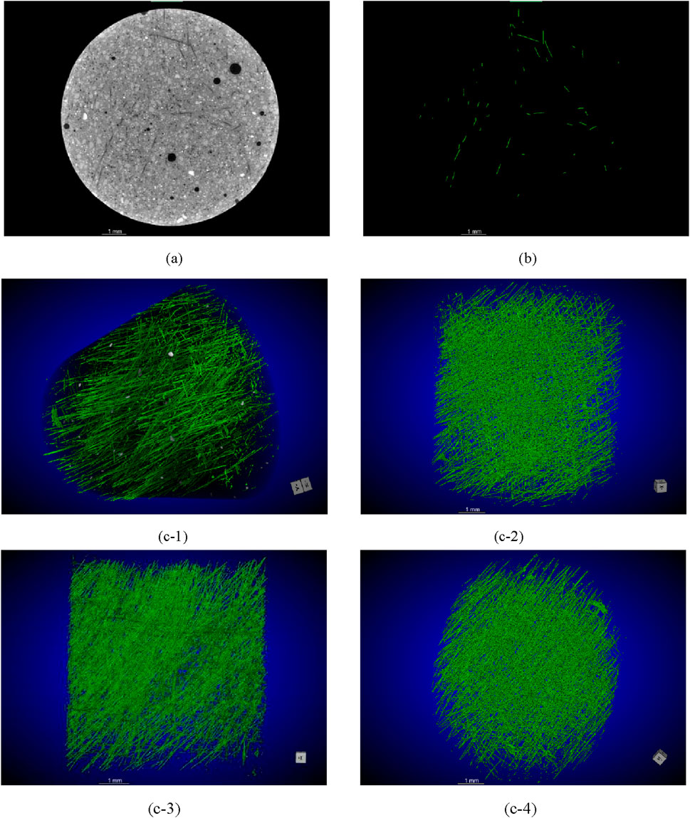
Figure 11. ROI segmentation and 3D reconstruction of the ECC with 0.2% of the CNCs: (A) original 2D slice image; (B) ROI segmentation by the deep learning model; (C) 3D reconstruction of the fibers at different angles.
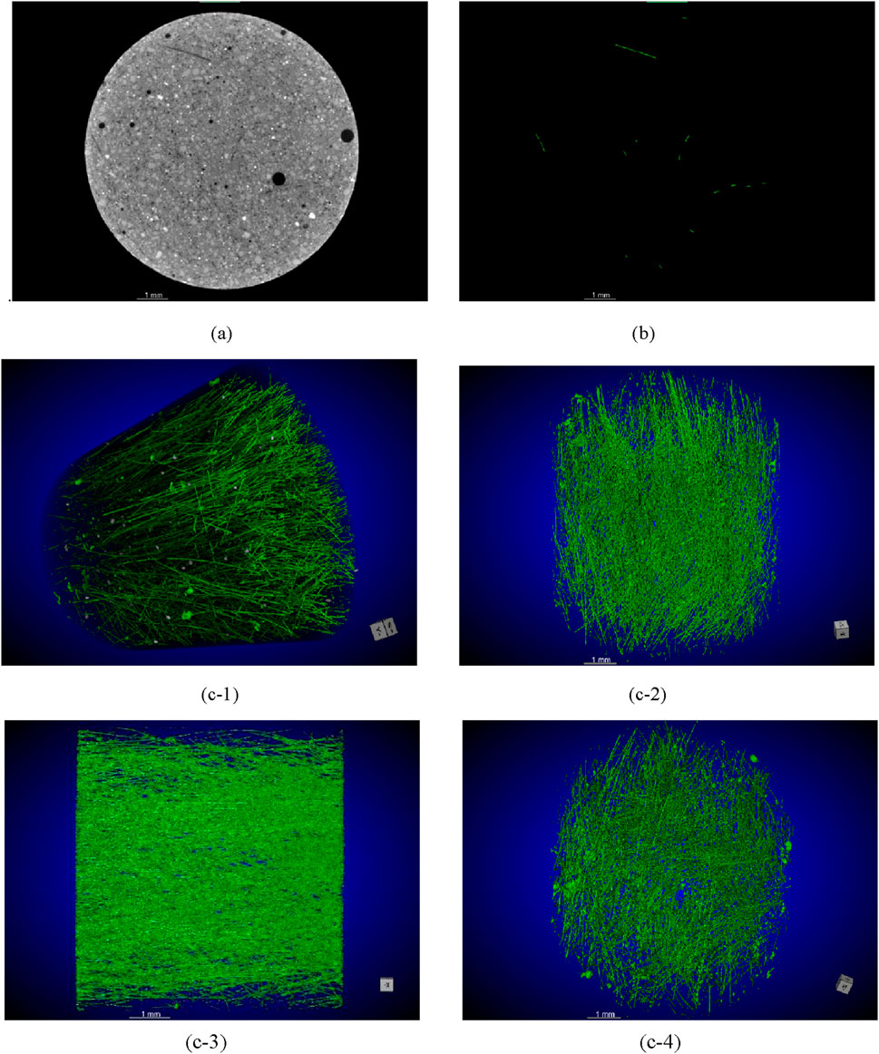
Figure 12. ROI segmentation and 3D reconstruction of the ECC with 0.4% of the CNCs: (A) original 2D slice image; (B) ROI segmentation by the deep learning model; (C) 3D reconstruction of the fibers at different angles.
A fluorescence technology was proposed to evaluate the dispersion of the fibers in the 2D plane (Torigoe et al., 2003; Yeon et al., 2009). Since the 3D image reconstruction technique has been utilized to detect the porosity and internal defects of cementitious composites, it is also feasible to reconstruct the fibers inside cementitious composites in 3D images (Liu et al., 2013). In the current work, although the dispersion of the PVA fibers was evaluated by a qualitative method instead of a quantitative method due to the limitation of the software utilized, the results obtained were still valuable for the application of CNCs and the evaluation of the fiber distribution.
4 Conclusion
This work preliminarily investigates the application of a green renewable nano-material, i.e., cellulose nanocrystals, in preparing engineered cementitious composites. To this end, a series of systematic analyses was conducted to study the effect of the CNCs on the rheology, microstructure, mechanical properties, and fiber distribution of the ECC. The following conclusions can be drawn from the findings of this work:
(1) The addition of the CNCs had an obvious effect on the yield stress and plastic viscosity of the ECC matrix, and the CNCs could be used as a viscosity-enhancing admixture to adjust the viscosity of the fresh cement matrix.
(2) LF-NMR analysis confirmed that the addition of the CNCs effectively reduced the total porosity of the ECC and refined its pore size distribution, improving its compactness.
(3) The average compressive strength of the ECC significantly improved with an increase in the amount of the CNCs owing to their filler effect. At a CNC content of 0.1%, 0.2%, and 0.4%, the compressive strength was enhanced by 19.6%, 26.6%, and 33% respectively. The compressive strength of ECC decreased with the increase of FA content, because a higher replacement of OPC by FA led to a decreasing cement hydration degree.
(4) Raising the CNC content from 0% to 0.4% dropped the tensile strain-hardening capacity of the ECC from 1.6% to 0.5%. However, the corresponding initial cracking strength increased steadily from 3.6 to 5.1 MPa. Further, the incorporation of 0.1% CNCs could effectively compensate for the decrease in strength due to the existence of more FA, while a relatively high level of tensile strain capacity as well as tight crack width remained. Thus, an optimal CNC content of 0.1% was suggested for ECC, which produced an enhanced strength and an acceptable drop in tensile strain capacity.
(5) By the application of X-ray micro-CT, the fiber distribution was investigated through the ROI extraction and 3D reconstruction images. A significant improvement in the fiber distribution could be seen with the addition of the CNCs since they controlled the viscosity of the fresh matrix in a reasonable range.
In future works, it remains to be demonstrated the theory that CNC, as a rod-shaped whisker, might resist microscopic cracks, and it will be difficult for the CNCs distributed in the matrix through the electron microscope. Moreover, the CNCs played an important role in enhancing the strength of the matrix, so engineering the interface between the matrix and fibers to avoid the rupture of PVA fibers is crucial in better meeting the requirement of the pseudo-strain-hardening behavior. It is worth mentioning that the characteristics of CNCs that are conducive to the strength development of ECC have great potential in the development of high-strength ECC. CNCs can be considered for high-strength ECC developed by PE fibers.
Data availability statement
The original contributions presented in the study are included in the article/supplementary material, further inquiries can be directed to the corresponding authors.
Author contributions
XY: Conceptualization, Methodology, Writing–original draft. J-GR: Investigation, Methodology, Writing–review and editing. L-XL: Conceptualization, Data curation, Writing–review and editing. ZW: Supervision, Writing–review and editing. Q-HZ: Data curation, Formal Analysis, Supervision, Writing–review and editing, Q-LL: Funding acquisition, Supervision, Writing–review and editing.
Funding
The author(s) declare that financial support was received for the research, authorship, and/or publication of this article. This work was supported by the National Natural Science Foundation of China with Grant (No. 52078282).
Conflict of interest
Authors Jian-Guo Ren and Qiao-Ling Liu were employed by Engineering Research Institute of Appraisal and Strengthening of Shandong Jianzhu University Co., Ltd. Author Lian-Xu Li was employed by China Tobacco Shandong Industrial Co., Ltd.
The remaining authors declare that the research was conducted in the absence of any commercial or financial relationships that could be construed as a potential conflict of interest.
Publisher’s note
All claims expressed in this article are solely those of the authors and do not necessarily represent those of their affiliated organizations, or those of the publisher, the editors and the reviewers. Any product that may be evaluated in this article, or claim that may be made by its manufacturer, is not guaranteed or endorsed by the publisher.
References
Arain, M. F., Wang, M., Chen, J., and Zhang, H. (2019). Study on PVA fiber surface modification for strain-hardening cementitious composites (PVA-SHCC). Constr. Build. Mater. 197, 107–116. doi:10.1016/j.conbuildmat.2018.11.072
Cao, Y., Tian, N., Bahr, D., Zavattieri, P. D., Youngblood, J., Moon, R. J., et al. (2016). The influence of cellulose nanocrystals on the microstructure of cement paste. Cem. Concr. Compos. 74, 164–173. doi:10.1016/j.cemconcomp.2016.09.008
Cao, Y., Zavaterri, P., Youngblood, J., Moon, R., and Weiss, J. (2015). The influence of cellulose nanocrystal additions on the performance of cement paste. Cem. Concr. Compos. 56, 73–83. doi:10.1016/j.cemconcomp.2014.11.008
Cappellari, M., Daubresse, A., and Chaouche, M. (2013). Influence of organic thickening admixtures on the rheological properties of mortars: relationship with water-retention. Constr. Build. Mater. 38, 950–961. doi:10.1016/j.conbuildmat.2012.09.055
Ding, C., Guo, L., Chen, B., Xu, Y., Cao, Y., and Fei, C. (2019). Micromechanics theory guidelines and method exploration for surface treatment of PVA fibers used in high-ductility cementitious composites. Constr. Build. Mater. 196, 154–165. doi:10.1016/j.conbuildmat.2018.11.118
Ding, Y., Liu, J. P., and Bai, Y. L. (2020). Linkage of multi-scale performances of nano-CaCO3 modified ultra-high performance engineered cementitious composites (UHP-ECC). Constr. Build. Mater. 234, 117418. doi:10.1016/j.conbuildmat.2019.117418
Ghafari, E., Costa, H., and Júlio, E. (2015). Critical review on eco-efficient ultra high performance concrete enhanced with nano-materials. Constr. Build. Mater. 101, 201–208. doi:10.1016/j.conbuildmat.2015.10.066
Horikoshi, T., Ogawa, A., Saito, T., and Hoshiro, H. (2006). Properties of polyvinyl alcohol fiber as reinforcing materials for cementitious composites. Int. RILEM Work. High. Perform. Fiber Reinf. Cem. Compos. Struct. Appl. 2, 145–153.
Jiang, S., Shan, B., Ouyang, J., Zhang, W., Yu, X., Li, P., et al. (2018). Rheological properties of cementitious composites with nano/fiber fillers. Constr. Build. Mater. 158, 786–800. doi:10.1016/j.conbuildmat.2017.10.072
Keskinateş, M., and Felekoğlu, B. (2018). The influence of mineral additive type and water/binder ratio on matrix phase rheology and multiple cracking potential of HTPP-ECC. Constr. Build. Mater. 173, 508–519. doi:10.1016/j.conbuildmat.2018.04.038
Kumar, R., and Bhattacharjee, B. (2003). Porosity, pore size distribution and in situ strength of concrete. Cem. Concr. Res. 33, 155–164. doi:10.1016/S0008-8846(02)00942-0
Li, M., and Li, V. C. (2013). Rheology, fiber dispersion, and robust properties of Engineered Cementitious Composites. Mater. Struct. 46, 405–420. doi:10.1617/s11527-012-9909-z
Li, Q., Gao, X., and Xu, S. (2016). Multiple effects of nano-SiO2 and hybrid fibers on properties of high toughness fiber reinforced cementitious composites with high-volume fly ash. Cem. Concr. Compos. 72, 201–212. doi:10.1016/j.cemconcomp.2016.05.011
Li, V. C. (2019). Engineered cementitious composites (ECC): bendable concrete for sustainable and resilient infrastructure. Berlin, Heidelberg: Springer.
Li, V. C., Wang, S., and Wu, C. (2001). Tensile strain-hardening behavior or polyvinyl alcohol engineered cementitious composite. ACI Mater. J. 98, 483–492. doi:10.14359/10851
Li, V. C., Wu, C., Wang, S., Ogawa, A., and Saito, T. (2002). Interface tailoring for strain-hardening polyvinyl alcohol-engineered cementitious composite (PVA-ECC). ACI Mater. J. 99, 463–472. doi:10.14359/12325
Liu, J., Li, C., Liu, J., Cui, G., and Yang, Z. (2013). Study on 3D spatial distribution of steel fibers in fiber reinforced cementitious composites through micro-CT technique. Constr. Build. Mater. 48, 656–661. doi:10.1016/j.conbuildmat.2013.07.052
Liu, Q., Peng, Y., Liang, L., Dong, X., and Li, H. (2019). Effect of cellulose nanocrystals on the properties of cement paste. J. Nanomater. 2019, 1–7. doi:10.1155/2019/8318260
Lu, C., Lu, Z., Li, Z., and Leung, C. K. Y. (2016). Effect of graphene oxide on the mechanical behavior of strain hardening cementitious composites. Constr. Build. Mater. 120, 457–464. doi:10.1016/j.conbuildmat.2016.05.122
Ma, H., Cai, J., Lin, Z., Qian, S., and Li, V. C. (2017). CaCO3 whisker modified Engineered Cementitious Composite with local ingredients. Constr. Build. Mater. 151, 1–8. doi:10.1016/j.conbuildmat.2017.06.057
Montes, F., Fu, T., Youngblood, J. P., and Weiss, J. (2020). Rheological impact of using cellulose nanocrystals (CNC) in cement pastes. Constr. Build. Mater. 235, 117497. doi:10.1016/j.conbuildmat.2019.117497
Pan, J., Cai, J., Ma, H., and Leung, C. K. Y. (2018). Development of multiscale fiber-reinforced engineered cementitious composites with PVA fiber and CaCO3 whisker. J. Mater. Civ. Eng. 30, 1–9. doi:10.1061/(ASCE)MT.1943-5533.0002305
Pang, C. M., Leung, C. K. Y., and Sun, W. (2014). Effect of rubber particles on properties of pseudo-ductile cementitious composites. Adv. Mater. Res. 936, 1456–1462. doi:10.4028/www.scientific.net/AMR.936.1456
Sahmaran, M., Bilici, Z., Ozbay, E., Erdem, T. K., Yucel, H. E., and Lachemi, M. (2013). Improving the workability and rheological properties of Engineered Cementitious Composites using factorial experimental design. Compos. Part B Eng. 45, 356–368. doi:10.1016/j.compositesb.2012.08.015
Struble, L. J., and Jiang, Q. (2004). Effects of air entrainment on rheology. ACI Mater. J. 101, 448–456. doi:10.14359/13483
Torigoe, S., Horikoshi, T., Ogawa, A., Saito, T., and Hamada, T. (2003). Study on evaluation method for PVA fiber distribution in engineered cementitious composite. J. Adv. Concr. Technol. 1, 265–268. doi:10.3151/jact.1.265
Tosun-Felekoǧlu, K., Felekoǧlu, B., Ranade, R., Lee, B. Y., and Li, V. C. (2014). The role of flaw size and fiber distribution on tensile ductility of PVA-ECC. Compos. Part B Eng. 56, 536–545. doi:10.1016/j.compositesb.2013.08.089
Wang, S., and Li, V. C. (2004). “Tailoring of pre-existing flaws in ECC matrix for saturated strain hardening,” in In proceedings of the fifth International Conference on Fracture Mechanics of Concrete and Concrete Structures, Vail, CO, January 12–16, 2004, 1005–1012.
Wang, X., Liu, C., Liu, S., Yan, C., Zhang, J., and Li, H. (2020). Compressive strength of pile foundation concrete in permafrost environment in China. Constr. Build. Mater. 247, 118431. doi:10.1016/j.conbuildmat.2020.118431
Xi, B., Zhou, Y., Yu, K., Hu, B., Huang, X., Sui, L., et al. (2020). Use of nano-SiO2 to develop a high performance green lightweight engineered cementitious composites containing fly ash cenospheres. J. Clean. Prod. 262, 121274. doi:10.1016/j.jclepro.2020.121274
Xu, S., Lyu, Y., Xu, S., and Li, Q. (2019). Enhancing the initial cracking fracture toughness of steel-polyvinyl alcohol hybrid fibers ultra high toughness cementitious composites by incorporating multi-walled carbon nanotubes. Constr. Build. Mater. 195, 269–282. doi:10.1016/j.conbuildmat.2018.10.133
Yang, E. H., Yang, Y., and Li, V. C. (2007). Use of high volumes of fly ash to improve ECC mechanical properties and material greenness. ACI Mater. J. 104, 620–628. doi:10.14359/18966
Yeon, B., Kim, J., Kim, J., and Yong, Y. (2009). Quantitative evaluation technique of Polyvinyl Alcohol (PVA) fiber dispersion in engineered cementitious composites. Cem. Concr. Compos. 31, 408–417. doi:10.1016/j.cemconcomp.2009.04.002
Keywords: cellulose nanocrystals (CNCs), engineered cementitious composites (ECC), rheology, pore size distribution, tensile strain-hardening capacity, fiber distribution
Citation: Yang X, Ren J-G, Li L-X, Wang Z, Zhang Q-H and Liu Q-L (2024) A preliminary investigation of incorporating cellulose nanocrystals into engineered cementitious composites. Front. Mater. 11:1443517. doi: 10.3389/fmats.2024.1443517
Received: 04 June 2024; Accepted: 21 August 2024;
Published: 04 September 2024.
Edited by:
Yao Ding, Chongqing University, ChinaReviewed by:
Ming-Feng Kai, Hong Kong Polytechnic University, Hong Kong SAR, ChinaHonglei Chang, Shandong University, China
Copyright © 2024 Yang, Ren, Li, Wang, Zhang and Liu. This is an open-access article distributed under the terms of the Creative Commons Attribution License (CC BY). The use, distribution or reproduction in other forums is permitted, provided the original author(s) and the copyright owner(s) are credited and that the original publication in this journal is cited, in accordance with accepted academic practice. No use, distribution or reproduction is permitted which does not comply with these terms.
*Correspondence: Zhen Wang, emhlbndhbmcyNUAxMjYuY29t; Qi-Hang Zhang, eHp4eW54bkAxNjMuY29t