 Jiuyang Li1
 Jingwei Luo
 Li Chen
- 1School of Civil Engineering, Changchun Institute of Technology, Changchun, China
- 2Shenyang Nonferrous Metallurgy Design and Research Institute Co., LTD., Shenyang, China
Concrete faces the difficulties of low tensile strength and poor crack resistance in building structures. In order to remedy this deficiency. In this paper, steel-polypropylene hybrid fiber reinforced concrete (SPFRC) was prepared by adding steel fiber (SF) and three kinds of polypropylene fiber (PF) to C50-grade concrete. The mechanical properties and microstructure of SPFRC were studied with different fiber combinations and content, obtaining the best hybrid combination. Based on this, the bending resistance and cracking of SPFRC beam members were investigated. The results demonstrate that the addition of fiber improves the compressive strength of ordinary concrete by 0.16% ∼ 17.69%, the splitting tensile strength by 15.18% ∼ 47.45%, and the bending strength by 3.54% ∼ 26.77%. Compared with single-fiber concrete, the hybrid fiber can achieve better internal microstructure, which further enhances the mechanical properties of the material. Hybrid fibers overlap within concrete beams, effectively redistributing stress and inhibiting the formation and propagation of cracks. For the three types of SPFRC beams, the cracking load is increased by 14.29% ∼ 28.57% compared with PC beam, the ultimate bearing capacity is increased by 9.68% ∼ 19.35%. The optimal dosage is determined as 1.0% SF, 0.6% Embossed polypropylene fiber (PBF). It provides reference for the application of SPFRC in flexural members.
1 Introduction
Since its inception, concrete materials have been widely utilized in civil engineering due to their high compressive strength, good plasticity, and ease of availability. However, as concrete applications have expanded, its weaknesses, such as low tensile strength, poor crack resistance, and inadequate durability, have become more pronounced. To meet the increasing demands for concrete performance in engineering, numerous researchers have continuously enhanced concrete performance by modifying aggregates, adjusting mix ratios, using admixtures, and employing various other methods (Li et al., 2022; Sun et al., 2022; Li et al., 2024a). One such method, fiber concrete, involves adding fibers to concrete to restrain and impede crack formation and improve the strength and toughness of the material.
Steel fiber (SF) is a type of metal hard fiber with excellent mechanical properties and a simple production process. These characteristics make it suitable for concrete fiber blending requirements. In 1911, Graham from the United States first experimented with adding SF to concrete, demonstrating the excellent performance of SF concrete through tests. Song and Hwang (2004) research indicated that the participation of SF can increase the compressive strength by 15.3% and the splitting tensile strength by 98.3%. The research of Ramadoss et al. (2023) shows that when the bulk content of SF is 1.5% and the replacement rate of silica ash is 15%, the compressive strength and folding strength increase by 33.41% and 66.67%, respectively. Ahanger and Tiwary (2024) use SF to strengthen recycled aggregate concrete, showing that with 1.5% SF content, compared with PC, the compressive strength increased from 45.5 to 62.6 MPa, and the flexural strength increased by 43.48%. Polypropylene fiber (PF) in the middle of the last century by the Italian Montecatini company took the lead in industrial production. Since its birth, it has attracted scholars to study it. PF density is usually between 0.89 ∼ 0.96 g/cm3, elongation between 15% and 30%, insoluble in water, and good corrosion resistance. In addition, as an organic fiber material, PF is cheaper than other fibers, so it is widely used in engineering fields such as basement floors, parking lot floors, and industrial and civil buildings (Vedernikov et al., 2022; Xian et al., 2024a). Abousnina et al. (2021) mixed PF into concrete, studied its mechanical properties, working properties, and microstructure, and the results showed that, Although PF reduces the workability of concrete, it significantly increases the toughness of the matrix, which is different from the brittle failure of ordinary concrete. PF concrete shows a progressive failure mode. In addition, under the same volume content, high elastic modulus fiber has a better strengthening effect on concrete, while organic polymer fiber can improve the toughness of concrete materials (Wang and Wu, 2002; Qing et al., 2017).
The properties and characteristics of various types of fibers vary, leading to differing effects when added to concrete to improve its working and mechanical properties (Ding et al., 2022; Li et al., 2023a). When multiple fibers with different properties are mixed into concrete, they can synergistically enhance the performance of concrete in various dimensions (Abed et al., 2023; Awad et al., 2023; Kun et al., 2023). For instance, Khan et al. (2022) studied the steel-basalt fiber concrete and demonstrated a 43.0% increase in compressive strength compared to regular concrete at specific dosages. Additionally, Muhyaddin (2023) research on ultra-high performance concrete (UHPC) indicated a 6.0% strength improvement when using a composite of steel fiber and glass fiber compared to using either fiber individually. Li et al. (2023b) reinforced concrete matrix with PF and SF to make up for the defects caused by coal gangue aggregate. The test results showed that hybrid fibers could cooperatively improve the microstructure of coal gangue concrete and make it meet the requirements of C30 concrete strength grade. The research of Bhogone and Subramaniam (2022) pointed out that the mixture of SF and PF in concrete can significantly reduce the development of early cracks and improve the fracture pattern. Due to its low elastic modulus, low density, and good ductility, PF can restrain the formation of early micro-cracks in concrete and enhance compactness. In addition, SF has a high elastic modulus, which can act as a skeleton support for the concrete matrix, accept the stress transmitted by PF and cement slurry, and restrain the development of cracks after concrete cracking (Liu and Han, 2019). SF and PF overlap each other to form a complex spatial structure. Under the appropriate dosage, the two kinds of fibers can achieve complementary advantages and produce the “positive hybrid effect”. S.R. Shashikumara applied these two fibers to concrete beams and showed that PF delayed crack formation and reduced crack width before cracking, while SF fibers showed better bearing capacity at yield and ultimate load points (Shashikumara et al., 2023). Abdulrahman Abbadi conducted static load tests on concrete beams with hybrid fiber systems (coarse PF, micro PF and SF). The data show that the cracking load value of hybrid fiber is increased by 14% compared with that of concrete beams doped with SF, which can delay the crack occurrence more effectively and reduce the deflection and reinforcement strain (Abbadi et al., 2022). Dipti Ranjan Sahoo conducted an experimental study on the flexural performance of SF-PF hybrid concrete beams, and the results showed that the addition of hybrid fibers can redistribute tensile stress at cracks, improve ductility and maintain the integrity of the beams. However, when the fiber content is too high, the ultimate load value of the beam decreases instead of increasing (Sahoo et al., 2015). Therefore, finding the right mixture of materials is the basis of SPFRC beam application.
The preliminary study of the research group shows that among the four types of steel fiber (shear type, end hook type, copper plated type, wave type), the shear steel fiber has the most significant strengthening effect on concrete (JGJ55-2011, 2011; Li et al., 2024b). Therefore, based on C50 concrete, this paper combines shear steel fiber and polypropylene fiber of three different types wavy type (PAF), embossed type (PBF), and monofilament type (PCF) into concrete to prepare steel-polypropylene hybrid fiber reinfored concrete (SPFRC). And conducts mechanical properties tests and analysis to obtain the hybrid fiber combination that improves the mechanical properties of concrete. In addition, the microstructure and strengthening mechanism were analyzed by microscanning test. The beam members were made according to the optimal mixture amount, and the load-bearing properties of different types of SPFRC beams were studied by bending test, which provided a reference for the application of SPFRC in engineering.
2 Experimental summary
2.1 Raw materials
This experiment adopted (42.5) P.O. Portland cement produced by Changchun Yatai Cement Co., LTD. The coarse aggregate selection of granite crushing and screening after the size of 5–12 mm stone, as shown in Figure 1A. The fines is selected from local natural river sand, and after screening and drying, the fineness modulus is 2.7, which belongs to medium sand, as shown in Figure 1B. The selection of a naphthalene superplasticizer (CQJ-NX) can enhance the service behavior of fiber-reinforced concrete. The water that is used in the batch is ordinary tap water.
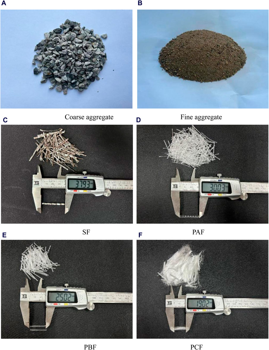
Figure 1. Coarse and fine aggregate and fibers appearance. (A) Coarse aggregate (B) Fine aggregate (C) SF (D) PAF (E) PBF (F) PCF.
Based on the previous research basis of the research group (JGJ55-2011, 2011; Li et al., 2024b), the performance indexes of the selected shear steel fiber are shown in Table 1, and its appearance is shown in Figure 1C. Three different types of PF, wavy type (PAF), embossed type (PBF), and monofilament type (PCF), were selected for the test. PAF has the longest length, wavy shape and smooth fiber surface. PBF shape is not curved, straight fiber, surface embossed pattern. PCF has the shortest length and is a filamentous shape with a small diameter, smooth surface and soft texture. Their various performance indexes are shown in Table 1, and their appearance is shown in Figures 1D–F.
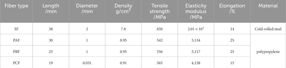
Table 1. Fiber performance index.
2.2 Experimental design
2.2.1 Mix ratio design
The base concrete of this test is C50, and the amount of materials required for C50 common concrete is calculated according to the Design Regulations for Common Concrete Mix Ratio (JGJ55-2011) (GB/T 50081-2019, 2019).
The material properties test was divided into two parts. The selection range of fiber content comes from the research group’s previous research basis (JGJ55-2011, 2011; Li et al., 2024b). First, the steel fiber (SF) content was 0, 0.4%, 0.6%, 0.8%, 1.0%, and 1.2%, and the cubic compressive strength, splitting tensile strength, and folding strength were tested to obtain the optimal SF content. On this basis, the wave type (PAF), embossed type (PBF), and monofilament type (PCF) polypropylene fiber were mixed with SF respectively, and the three mechanical properties were tested in four groups, and the optimal mixture of hybrid fiber concrete was selected. The specific design is shown in Table 2.

Table 2. Experimental group design.
2.2.2 Specimen preparation and curing
According to the specification (GB/T 50081-2019) (Li et al., 2023d) and combined with the test indexes. Test blocks with side lengths of 100 mm were utilized for the evaluation of compressive and splitting tensile strength, whereas prismatic test blocks with dimensions of 100 mm × 100 mm × 400 mm were employed for the assessment of flexural strength. Each group consisted of three specimens.
For fiber-reinforced concrete, the mixing process is crucial a factors influencing the performance of concrete. An incorrect mixing process can easily lead to fiber agglomeration and affect the test results. Therefore, the mixing process of fiber concrete was optimized in this experiment. It was necessary to manually disperse the fiber and then add it to the mixer, dry mix it until the fiber was dispersed and evenly mixed with the aggregate, and then add water for mixing. HJW-60 type single-axis horizontal mixer was used for concrete mixing. After the mixing was completed, the mold was filled and vibrated on the shaking table until the bubbles were discharged. After the surface floating slurry was smooth, it was left for 24 h and then molded, and the concrete was put into a standard curing box with a temperature of 20°C and a relative humidity of 95% for 28d.
2.3 Experimental method
2.3.1 Compressive strength test
This material mechanical property test was conducted by the specification (GB/T 50081-2019) (Li et al., 2023d). The compressive strength test was carried out by the YAW-2000 pressure testing machine. The test block was positioned at the center of the pressure plate, with the formed side of the test block acting as the pressure surface. The automatic loading was controlled by the computer at a loading rate of 0.5 MPa/s, and the loading was stopped after the specimen was damaged.
The compressive strength of the specimen is calculated by Formula 1, and the arithmetic average strength of the obtained three test blocks (accurate to 0.1 MPa) is taken as the compressive strength of the cube. As the test block is a non-standard cube, the strength values should be adjusted by the dimensional conversion factor of 0.95.
Type: F——block breaking load (N);
2.3.2 Splitting tensile strength test
The splitting tensile strength test was conducted using the YAW-2000 pressure testing machine. The pressure surface was the side of the specimen forming surface. Prior to the test, the position of the middle splitting surface was marked on the surface of specimen, and the splitting fixture was aligned with the marked line before loading. The loading rate was 0.05 MPa/s. When the test block is split or the vertical crack in the middle is penetrated, the test is declared to be over.
The splitting tensile strength of specimens is determined using Formula 2, and the average strength of the three test blocks obtained (rounded to 0.1 MPa) is considered as the splitting tensile strength of this group. As the test block is a non-standard cube, the strength values should be adjusted by the dimensional conversion factor of 0.85.
Type: F——Failure load of test block (N);
A——Test block splitting surface area (mm2);
fts——Concrete splitting tensile strength (MPa).
2.3.3 Flexural strength test
The flexural strength test utilized the MW-50D microcomputer-controlled electronic universal testing machine. The bearing surface was formed by the side of the specimen, and the four-point loading method was employed. The load was transferred by the actuator to the loading steel plate, and the loading steel plate was distributed to the specimen through two hard steel cylinders. Before the test starts, position marking lines are drawn at the support position and loading position. The loading rate of the testing machine is 0.08 MPa/s. When the loading rate drops significantly, the specimen is declared damaged and the test ends.
The flexural strength was numeration according to Formula 3, and the arithmetic average strength of the three specimens (accurate to 0.1 MPa) was taken as the flexural strength of the group of specimens. Since the size of the specimen is non-standard, it is necessary to multiply the dimensional conversion factor by 0.85.
Type: F——Failure load of specimen (N);
l——Support spacing (mm);
b——Section width of sample (mm);
h——Section height of sample (mm);
ff——Concrete flexural strength of (MPa).
2.3.4 SEM micromorphology test
The micromorphology scanning test was performed with a HITACHI S-3400 scanning electron microscope. Operation steps: 1) Select the block broken material after the mechanical test as the sample, the sample size is about 8 mm × 8 mm × 5 mm; 2) Fix the sample on the sample bearing table with tape, clean the dust on the surface of the sample and the sample bearing table with the air bag, and invert the sample bearing table to test whether the sample is firmly pasted; 3) Put the sample into the gold spraying equipment for gold spraying treatment. 4) Put the sample bearing table into the electron microscope sample room, and adjust the magnification, color contrast, etc., to obtain the ideal microstructure diagram.
3 Test results and analysis
3.1 Compressive strength of cube
3.1.1 Failure pattern
The failure pattern of the compressive strength test is depicted in Figure 2A, and the progressive loss of effectiveness of a standard concrete test block is illustrated. The outer layer of concrete surrounding the test block has been entirely removed, indicating severe damage. The residual portion exhibits an hourglass shape, characteristic of brittle failure.
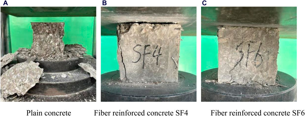
Figure 2. Cube compressive failure pattern. (A) Plain concrete (B) Fiber reinforced concrete SF4 (C) Fiber reinforced concrete SF6.
Figures 2B, C show the failure modes of SF4 and SF6 fiber-reinforced concrete. Compared with ordinary concrete, SF reinforced concrete is relatively complete after failure, with no obvious concrete spalling phenomenon and only a small amount of concrete debris falling, indicating that the addition of fiber improves the failure mode of concrete, from brittle failure to plastic failure. This is because the fibers overlap with each other inside the test block to form a fiber cage structure, which can play a binding role when the specimen is damaged, inhibit the transverse deformation of the concrete, reduce the spalling of the concrete during the failure process, and ensure the integrity of the test block.
By comparing Figures 2B, C, it can also be found that with the increase of fiber content, the spalling phenomenon of concrete compression failure mode is weakened, the crack width is narrower during failure, and the shape of the test block is more complete during failure. Indicate that with the growth of fiber content, the development of cracks can be better restricted and the damage degree of the test block can be reduced. The failure pattern of the hybrid fiber specimen is similar to that of the single doped steel fiber specimen, the whole specimen is relatively complete, only some vertical cracks appear on the surface during failure, and the concrete debris drop is less.
3.1.2 Compressive strength results and analysis
The cube compressive strength test results are drawn as a histogram, as shown in Figure 3, and analyzed as follows:
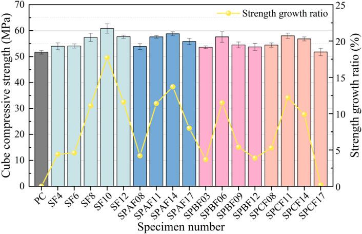
Figure 3. Fiber reinforced concrete cube compressive strength.
For the test group of separately incorporated SF, the cube compressive strength showed a tendency to rise and then diminish. When the SF content is 1.0%, the peak compressive strength reaches 60.82 MPa, which is 17.7% higher than that of PC. However, when the SF content further increases, the compressive strength begins to diminish, indicating that the SF content of 1.0% is the best volume content.
For the test group of SPAF. When the content of PAF is in the range of 0.08% ∼ 0.14%, the compressive strength shows an increasing trend, and the strengthening effect begins to weaken when the content exceeds 0.14%. When PAF content reaches 0.14%, the compressive strength is 58.78 MPa, which is 13.7% higher than that of PC. In summary, when the volume of PAF is 0.14, the compressive strength increases the most, which is the optimal content of PAF.
For the test group of SPBF, the compressive strength is higher than that of PC when the content of PBF is 0.3% ∼ 1.2%. The maximum compressive strength is 57.6 MPa when the PBF content is 0.6%. It is observed that the bar chart, when the slope of the bulk content section of 0.3% ∼ 0.6% is greater than that of the bulk content section of 0 ∼ 0.3%, the former is more effective in improving compressive strength. Therefore, when the bulk of PF is 0.6%, the improvement effect of compressive strength of concrete is the best.
For the SPCF test group, the compressive strength is obviously affected by the volume of PCF. With the increase of PCF content, the compressive strength decreases gradually. When the content reaches 0.17%, the compressive strength drops sharply. At this time, the lifting effect of fiber on concrete is almost 0. Therefore, to ensure the compressive strength of the SPFRC, the content of monofilament PF should be controlled at about 0.11%.
In summary, the improvement of compressive strength of hybrid fiber concrete is about 11%, which is slightly lower than that of pure steel fiber concrete, which is consistent with the results obtained in the literature (He, 2002). However, Irrespective of the fiber type, excessive fiber content can diminish the compactness of the concrete matrix, resulting in a weakened strength enhancement effect. Therefore, it is imperative to determine the optimal fiber content to establish a solid foundation for the application of subsequent beam members.
The fitting function can further express the relationship between the two parameters, and the mechanical properties of SPFRC can be accurately characterized by a quadratic polynomial. Similar to the literature (Dash et al., 2023; Lin et al., 2024; Xian et al., 2024b), this paper uses the origin function plotting tool to fit the test results, and selects polynomial function and exponential function fitting forms to obtain higher fitting accuracy. Figure 4 depicts the correlation between compressive strength and fiber content in fiber concrete.
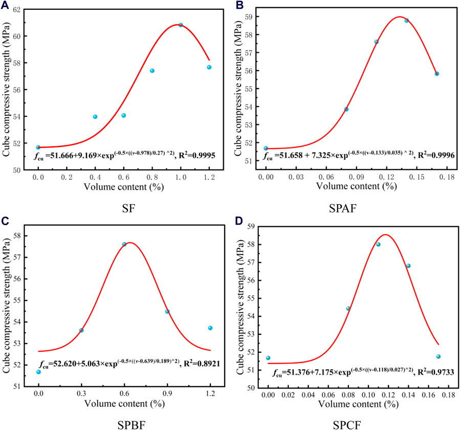
Figure 4. Compressive strength fitting curve. (A) SF (B) SPAF (C) SPBF (D) SPCF.
3.2 Splitting tensile strength
3.2.1 Failure pattern
The failure pattern of the tensile strength test is presented in Figure 5A is the failure pattern of the PC specimen. During the loading process, a small crack first appeared near the loading point, but the appearance did not change significantly. After reaching the ultimate load, the small crack near the loading plate suddenly ran through the test block along the splitting line, and the test block split in two, showing typical brittle failure characteristics.
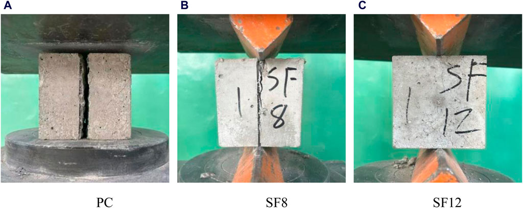
Figure 5. Cube cleavage damage pattern. (A) PC (B) SF8 (C) SF12.
Taking SF8 and SF12 as examples, the damage patterns of fiber-reinforced concrete are shown in Figures 5B, C. During the loading process, in addition to the microcrack at the loading point, accompanied by the “ding ding” sound of fiber slip. When the ultimate load is reached, the small cracks at the loading point gradually spread to the middle, but unlike PC concrete, the test block is not split in half, indicating that the fiber plays a clear pulling role, showing ductile failure characteristics.
By comparing Figure 5B with Figure 5C, it can be found that the fiber content affects the failure form of the splitting tensile test. As the fiber content increases, the inhibition effect of fiber on crack development is stronger, reflecting that the crack width is smaller and smaller at the macro level, which further indicates that fiber can enhance the tensile failure mode of concrete.
3.2.2 Analysis of splitting tensile strength results
The results of the splitting tensile strength test are drawn as a bar chart, as shown in Figure 6, and the following analysis is carried out.
Figure 6. Splitting tensile strength of fiber reinforced concrete.
For the test group of SF, the splitting tensile strength decreased slightly when the volume content was 0.4%. This indicates that it is challenging to achieve a strengthening effect when the SF content is too low, and it can negatively impact the bond between the concrete matrix aggregate and the cementing material. With the increase of fiber content, SF gradually distributes evenly and overlaps with each other in the concrete, forming a complete network structure (Liu et al., 2021), which makes the splitting tensile strength show an increasing trend. The splitting tensile strength of SF10 is 0.32 MPa higher than that of SF8, and the growth rate is 7%. Considering the economic cost factors in the project, 1.0% can be used as the best SF dosage.
Within the SPAF experimental group, a variation in fiber content ranging from 0.08% to 0.14% led to a slight improvement in mechanical properties, resulting in an overall improvement rate of 33% ∼ 40% compared to PC. Notably, at a volume content of 0.14%, the maximum splitting tensile strength reached 5.13 MPa, marking a 10.80% increase compared to the strength of concrete with SF alone. However, an increase in PAF content correlated with a decreasing trend in splitting tensile strength, exhibiting a decrease of 4.09% compared to the highest value, although this decrease was not significant. Therefore, maintaining a dosage within the range of 0.08% ∼ 0.14% can effectively achieve the goal of enhancing tensile strength.
For the SPBF experimental group, when the PBF content is 0.9%, the splitting tensile strength reaches a peak value of 5.41 MPa, which is 47% higher than that of PC splitting tensile strength, and 16.85% higher than that of SF concrete with 1.0%, indicating that the hybrid fiber can enhance the strength of concrete effectively. When the fiber content reached 1.2%, the strength began to decrease to 3.70% of the peak value. Therefore, to improve the splitting tensile strength of concrete, it is recommended that the volume content of embossed PF is 0.9%.
For the experimental group of SPCF, the splitting tensile strength is the maximum value when the volume content is 0.11%, and the minimum value when the bulk content is 0.17%, which are 5.23 MPa and 4.82 MPa, respectively. The strength ratios of the two with plain concrete are 1.43 and 1.31, respectively. As a whole, when the volume content is 0.08% ∼ 0.17%, the effect of this hybrid fiber on the splitting tensile strength of concrete is always maintained at a high level, so to improve the splitting tensile strength of concrete, the volume content should be kept in the range of 0.08% ∼ 0.14%.
In summary, hybrid fibers can improve the splitting tensile strength of concrete matrix better than single-doped SF, and the fiber combination of SPAF14, SPBF09, and SPCF11 has the most significant effect on the gain of splitting tensile strength. The fitting of splitting tensile strength and fiber content of fiber concrete is shown in Figure 7.
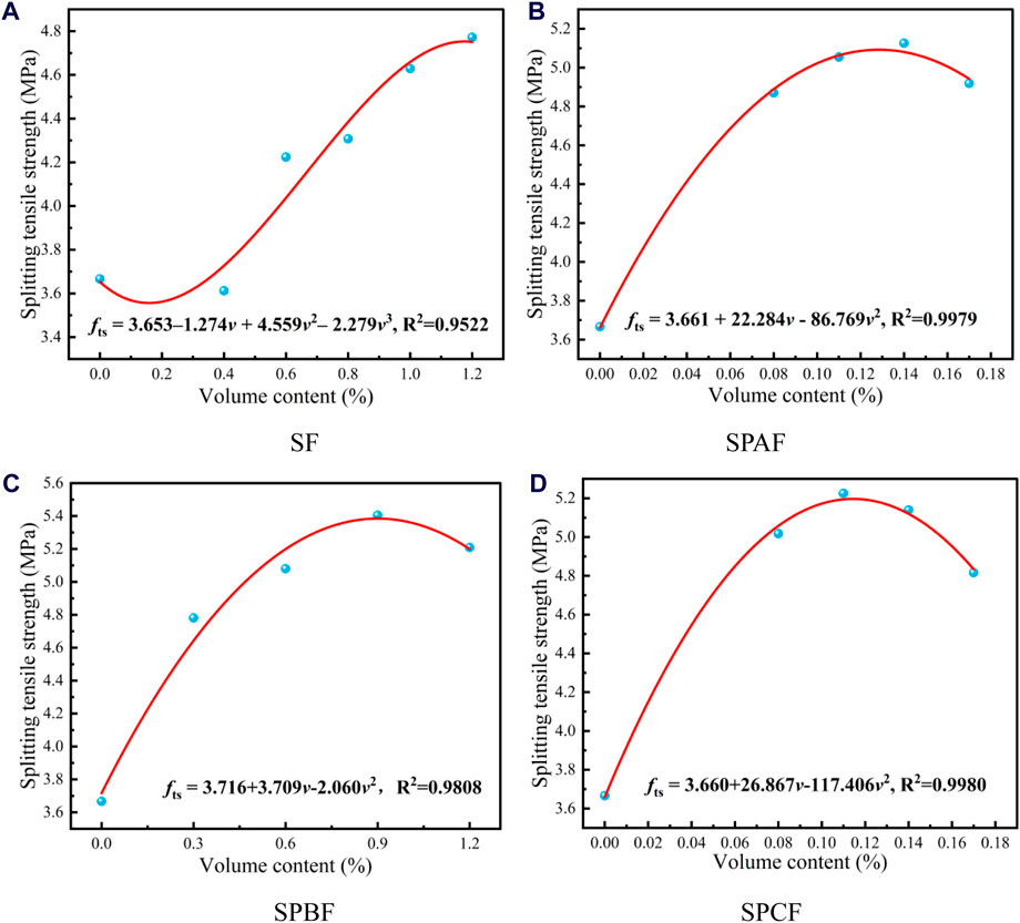
Figure 7. Split-tensile strength fitting curve. (A) SF (B) SPAF (C) SPBF (D) SPCF.
3.3 Flexural strength
3.3.1 Failure pattern
The failure pattern observed in the flexural strength test is illustrated in Figure 8. A notable disparity exists between the bending failure modes of ordinary concrete and fiber concrete specimens. When the ordinary concrete specimen reaches its maximum load, a sudden brittle failure occurs without prior warning. The specimen instantaneously fractures into two parts from the middle at the point of failure. In the flexural test of fiber-reinforced concrete, a small crack emerges at the bottom of the span during the loading process, accompanied by a slight fiber fracture sound. With increasing load, the crack width continues to expand, and visible cracks appear on the specimen upon reaching the ultimate load. However, the specimen does not completely disconnect, as depicted in Figure 8B. Even after reaching the ultimate load, the specimen maintains partial bearing capacity with increasing vertical deflection. Upon removal of the specimen after the test, residual fibers of the fracture surface on both sides are discernible from the cracks. These observations indicate that the addition of fiber can effectively mitigate the brittle failure of concrete.
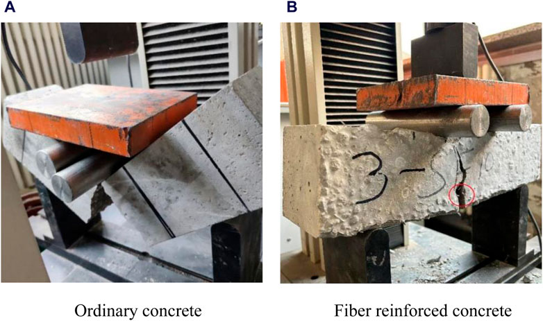
Figure 8. Bending test failure pattern. (A)Ordinary concrete (B) Fiber reinforced concrete.
3.3.2 Analysis of bending strength results
The data obtained from the flexural test are drawn into the intuitive bar chart shown in Figure 9, and the following analysis is carried out.
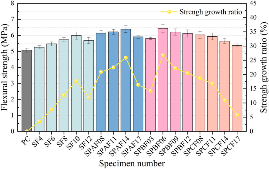
Figure 9. Flexural strength of fiber reinforced concrete.
For the SF test group, the flexural strength increased first and then decreased when the SF content ranged from 0.4% to 1.2%. When the SF content was 1.0%, the flexural strength reached a peak of 5.98 MPa. Due to the uniform distribution of SF in concrete, the SFs located in the tension area play the role of “micro-reinforcement” (GB/T50152-2012, 2012), and bear part of the load during the generation and development of cracks, limiting the development speed of cracks, and thus improving the bending and cracking resistance of concrete (Li et al., 2024c). When the SF content is too high, the densification reduction caused by a large number of fibers is gradually serious, weakening the gain effect, resulting in a gradual slowdown in the growth rate of flexural strength, or even a decline. The optimal SF content is 1.0%.
For the experimental group of SPAF, the increased ratio of the hybrid fiber to the bending strength of concrete is more than 15%, indicating that the mixed fiber has a better effect on the bending strength of concrete in the range of 0.08% ∼ 0.17%. When the volume content is 0.14%, the flexural strength is 6.39 MPa, which is 26% higher than that of plain concrete and 6.86% higher than that of SF concrete with 1.0% volume content. When the volume content reached 0.17%, the strengthening effect began to weaken, and the strength decreased by 7.51% compared with the highest value. Therefore, the recommended dosage range for improving the flexural strength of concrete is 0.08% ∼ 0.14%.
For the experimental group of SPBF, the flexural strength of hybrid fiber concrete showed a trend of first increasing and then slowly decreasing in the range of 0.3% ∼ 1.2% PB fiber volume. When the volume content reaches 0.6%, the bending strength reaches a peak value of 6.44 MPa, which is 1.36 MPa higher than plain concrete and 0.41 MPa higher than SF concrete. When the fiber content exceeds the optimal content, the bending strength decreases at a slow rate. When the fiber content is 1.2%, the flexural strength is reduced by 4.97% compared with the maximum value. Therefore, the optimal content of the hybrid fiber combination to improve the flexural strength of hybrid fiber concrete is 0.6%.
For the SPCF experimental group, the bending strength showed a continuous decreasing trend in the range of 0.08% ∼ 0.17. When the PCF content is 0.08%, the flexural resistance of concrete is the best, the maximum bending strength is 6.03 MPa, and the increase ratio is 19.69% compared with PC. The small diameter and low tensile strength of PCF result in easy clustering between fibers. The higher the dosage, the more noticeable this clustering becomes, which reduces the density of the matrix. To ensure that concrete maintains good bending resistance, the fiber content should be kept within the range of 0.08% ∼ 0.11%.
In summary, hybrid fibers have a good effect on improving the folding strength of the concrete matrix, among which SPBF14, SPBF06, and SPCF08 are the optimal combination of folding strength, which can provide reference for the subsequent design and calculation of beam members. The fitting of splitting tensile strength and fiber dosage of fiber concrete is displayed in Figure 10.
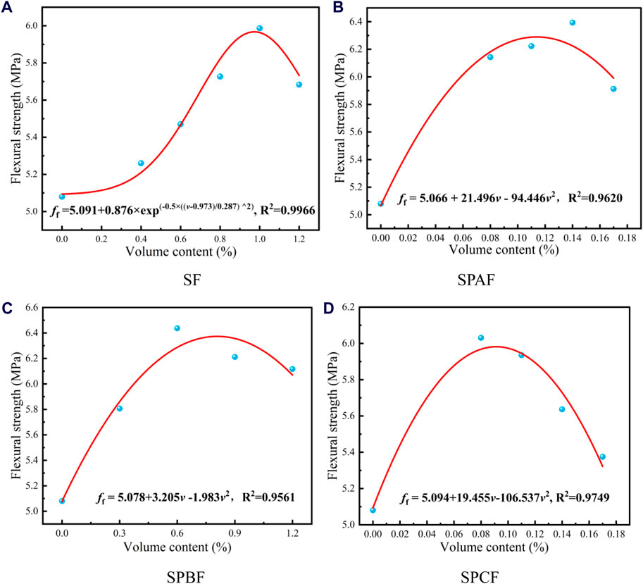
Figure 10. Flexural strength fitting curve. (A) SF (B) SPAF (C) SPBF (D) SPCF.
After a comprehensive analysis of the three mechanical properties, it is concluded that SPAF14, SPBF06, and SPCF11 are the optimal dosage combinations of SPFRC. It can provide a reference for the application of SPFRC in different components.
3.4 Microscopic analysis
3.4.1 Micromorphology analysis
Figure 11 is the microscopic map of the sample under a scanning electron microscope, and the underlying cause of the macroscopic phenomenon of SPFRC is analyzed from a microscopic perspective.
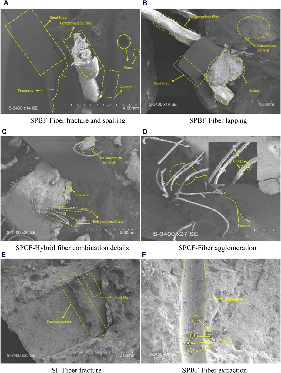
Figure 11. Microcosmic diagram of specimen. (A) SPBF-Fiber fracture and spalling (B) SPBF-Fiber lapping (C) SPCF-Hybrid fiber combination details (D) SPCF-Fiber agglomeration (E) SF-Fiber fracture (F) SPBF-Fiber extraction.
Figure 11A demonstrates the parallel distribution of PBF and SF. After pretreatment, the surface of PBF has continuous and obviously uneven patterns, which increases the contact area and adhesion between fiber and matrix and is conducive to giving full play to the toughening and strengthening effects of fiber. The water compounds attached to the surface of the fiber in the figure confirm the feasibility and effectiveness of this type of factory treatment method. Macroscopically, the splitting tensile strength of SPBF09 is 16.8% higher than that of SF10.
Figure 11B indicates the overlapping distribution of SF and PAF. Compared with PBF fiber, under the same length-diameter ratio, the unique wavy shape has a larger surface area and significantly increases the surface adhesion, thus increasing the bonding force with the cement matrix. In the process of concrete mixing and vibration, the mutual extrusion between aggregates and fibers will cause the fibers to bend and overlap with each other in a small amplitude. The microstructure enhancement of hybrid fibers is reflected in the increase of the flexural strength of the SPAF14 group by 6.7%.
Figures 11C, D show the hybrid effect of SF and PCF. In Figure 11C, it is evident that the diameter of the PCF differs significantly from that of the SF. In Figure 11C, fibers are observed to be still wrapped in a small amount of slurry material after the specimen has been damaged. Additionally, a substantial amount of hydration product (C-S-H) is attached to the surface of PCF in Figure 11D, providing evidence of the bonding force between such fibers and concrete.
In Figure 11C, the surface of the SF is flat and has a unique brushed metal stripe. Under the electron microscope, it is apparent that there is no gap between the SF and the concrete slurry, and the tight adhesion between the two is strong, which can give full play to the advantages of high elastic modulus and high tensile strength of the SF.
Through the above microscopic graphic analysis, it can be found that SF and PF can realize the synergistic mechanism in SPFRC. This is due to the low elastic modulus, low density, and good ductility of PF, which can restrain the formation of early micro-cracks in concrete and enhance the compactness of the matrix. In addition, SF has high elastic modulus and strong tensile strength, which can play the role of skeleton support for concrete matrix, accept the stress transmitted by PF and cement slurry, and restrain the development of cracks after concrete cracking. SF and PF overlap each other to form a complex spatial structure. Under the appropriate dosage, the two kinds of fibers can complement each other and produce the positive hybrid effect.
3.4.2 Analysis of fiber energy consumption forms
In Figure 11A, the microscopic details of the SF-PAF concrete are presented. This illustration displays two distinct fiber shapes and clearly depicts the failure form of PAF. In comparison to SF, PAF exhibits a smaller elastic modulus, softer texture, and superior ductility. The bond between the fiber and concrete primarily relies on the bite force of the surface pattern. Energy consumption can be categorized into fiber fracture and fiber pulling out, based on the different positions of crack development and fiber space.
When a crack is located near one end of the fiber, the bond between the fiber and the concrete is weakened. Consequently, when the load carried by the fiber surpasses the bond force, slippage between the fiber and the concrete occurs. If the crack is larger, the fiber will be pulled out, leaving obvious grooves in the concrete, as shown in Figure 11F. When the crack appears near the middle of the fiber, both sides of the crack have sufficient contact length to bond with the concrete. At this time, the fiber itself absorbs energy to bear the load, and due to the characteristics of small elastic modulus and large ductility, the internal stress concentration part of the fiber is the first to deform. The fiber appears to shorten between diameters and increase in length until it breaks and fails beyond the tensile strength, as shown in Figure 11E, and the section shape is irregular and rough.
In addition to the above two energy consumption modes, there is an obvious groove in Figure 11A that deserves attention. This phenomenon is not formed by the fiber being pulled out, but by the fiber being located right on the fracture surface, and the fiber is completely removed from the slurry during the stress process, without participating in the process of being subjected to force. At the same time, because the fiber-slurry interface transition zone is often a weak link, the distribution of fibers here will accelerate the development of cracks.
Figure 11E shows the microscopic details of fracture patterns of SF. The shear SF used in this test is a wavy flat strip type, so it can have a larger surface area to enhance the bonding force and reduce the probability of SF slip pulling out. SF has a large elastic modulus and small fracture ductility, which can absorb a lot of energy and delay the crack development during the crack development. In addition, the fracture of SF is a sudden fracture without signs, and the cross-section of SFs is usually more regular and flat.
PCF is very small in diameter, soft, and easy to deform, and the number of fibers is far more than other types of fibers under the same volume content, so fiber clustering is easy to occur. This phenomenon prevents the slurry from entering the interior of the fiber mass, and the fiber cannot be fully mixed with the slurry, becoming a weak link in the interior of the concrete, as shown in Figure 11D, a small part of monofilament PF is pulled out as a whole. This explains the sharp decline in strength caused by high PCF fiber content in SFPC17 test group, and the weakening effect of hybrid fibers is greater than the strengthening effect. In fact, the appropriate PCF content can be evenly distributed inside the concrete. On the one hand, the porosity inside the concrete is reduced and the density is improved. On the other hand, the chaotic distribution of the fibers makes the internal stress distribution more reasonable and enhance the mechanical properties of the concrete.
In summary, surface of the SF is relatively flat, and the energy consumption is mainly pulled out, and some SF breaks after absorbing a lot of energy. PAF and PBF can avoid fiber slippage by increasing the adhesion and biting force with concrete, so it mainly consumes energy for fiber fracture. The length-diameter ratio of PCF is large, and it is packed in concrete, so the energy consumption is mainly fiber fracture and fiber pulling out.
4 Application research of SPFRC beam members
4.1 Design and manufacture of test beam
Based on the analysis results of the mechanical properties and microstructure of SPFRC in Section 3, the beam members were fabricated by selecting the optimal content of three hybrid fiber combinations (SPAF14, SPBF06, SPCF11). The objective is to investigate the cracking and bending resistance of beams with different SPFRC dosage combinations. The test beam length l = 1,800 mm (calculated span l0 = 1,500 mm), the beam section size b × h = 150 mm × 300 mm, the longitudinal bearing longitudinal reinforcement was selected HRB400 rebar, and the vertical longitudinal reinforcement was selected HPB300 round longitudinal reinforcement. And ordinary concrete beams of the same size and reinforcement are made as a comparison. The size and reinforcement of the component are illustrated in Figure 12A.
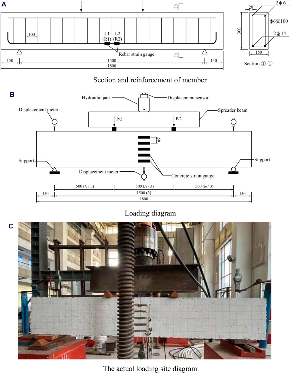
Figure 12. Beam loading test diagram. (A) Section and reinforcement of member (B) Loading diagram (C) The actual loading site diagram.
The components are made of steel molds, and foam glue is used to fill the gap after assembly, and a U-shaped clasp is used to limit the position of the steel mold to prevent mold expansion. Before pouring, a release agent is applied inside the steel mold to facilitate mold release. The optimal dosage is obtained in Chapter 3 of the configuration for composite pouring of the SPFRC beam, and standard cube test blocks are made for maintenance under the same conditions. Preserve the beam in a humid environment for 28d and cover it with plastic film to prevent water loss.
In this test, longitudinal reinforcement and concrete strain gauges of BMB120 type were used. Before pasting, the pasting position was smoothed and smooth and wiped with alcohol. Quick-drying adhesive is used to attach steel strain gauges and epoxy values are used to attach concrete. To ensure the stability and effectiveness of the test data, two longitudinal reinforcement strain gauges are arranged in the middle of the two tensile longitudinal reinforcement spans, denoting L1 (R1) and L2 (R2), and the attaching positions are shown in Figure 12A. Meanwhile, before loading, the concrete strain gauges are arranged in the middle of the beam spans at equal spacing along the beam height, with a spacing of 50 mm, and the distribution mode is shown in Figure 12B. The strain gauge was collected by the DH3821 data acquisition system.
4.2 Loading scheme
The flexural test use the four-point loading method with a support is 150 mm away from the beam end. The loading point is located at the third equal equinox of the effective span length l0, and the measuring point of the mid-span displacement and the measuring point of the support is set, as shown in Figure 12B. The hydraulic jack acts the load on the spreader beam and then transmits it to the loading point by the distribution beam. The device diagram is shown in Figure 12C.
Following the steps of the Chinese specification (GB/T 50152-2012) (Li et al., 2023c), pre-loading is carried out before formal loading to confirm the normal operation of test devices and measuring equipment such as components, distribution beams, and supports. During the formal loading process, each stage was loaded 5 kN and the load holding time was 3 min. The crack development was observed and marked, and the crack width was recorded and measured by the ZBL-F103 crack width meter. After the loading of each stage is completed and the measurement indicator is stable, the three displacement values and the strain values of the longitudinal reinforcement and concrete are recorded. When the load of concrete beam no longer increases and shows a downward trend, it is declared that the test beam has reached failure and the test is over. The failure pattern and crack width of the component were recorded by photographing.
4.3 Test results and analysis
Table 3 presents the cracking load (Load value of concrete beam at initial crack), ultimate load (The maximum load value that a concrete beam can achieve during loading), and mid-span deflection of the test beam. Both the cracking load and the ultimate load of SPFRC beam are more elevated than that of PC beam, and the hybrid fiber works well together to show a good “positive hybrid effect”. The ultimate load increase of the SPBF beam is the most significant, 8.82% higher than that of the SPBF beam and SPCF, and 19.35% higher than that of the PC beam. The improvement effect is obvious.
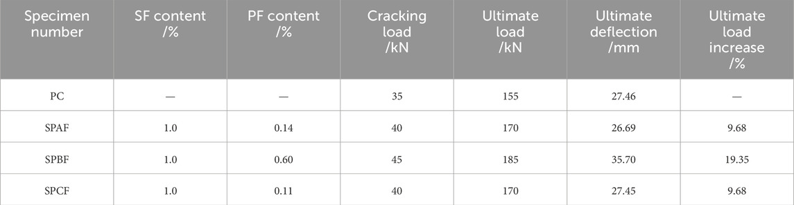
Table 3. Statistical table of crack load, ultimate load, mid-span deflection.
4.3.1 Failure pattern
The failure pattern of the test beam and the first crack at the bottom of the mid-span beam are depicted in Figure 13.

Figure 13. Beam failure pattern and initial crack width. (A) PC (B) SPAF (C) SPBF (D) SPCF.
The failure patterns of the four test beams are similar, and they all belong to the bending failure of the normal section, which is in line with the design expectation. The cracking loads of the four test beams are 35, 40, 45, and 40 kN respectively, indicating that hybrid fiber concrete improves the tensile strength of the material, delays the development of cracks, and increases the cracking load. In the course of the test, the main cracks were located in the middle of the span and some surrounding areas, and the new cracks that appeared with the increase of load were axisymmetrically distributed in the middle line of the test beam, and the failure pattern was in line with the expectation on the whole. The concrete in the compression area of the PC beam is crushed when the beam is damaged. On the contrary, the concrete in the compression zone is improved to varying degrees when the hybrid fiber is added to the beam when it reaches the ultimate load.
4.3.2 Load-deflection
The displacement data of the three measuring points during the test loading process are drawn into a line chart, as shown in Figure 14. To avoid damage to the collection equipment by the test, the displacement meter was removed after the load reached the ultimate load, so the displacement data of the load falling section was not recorded.
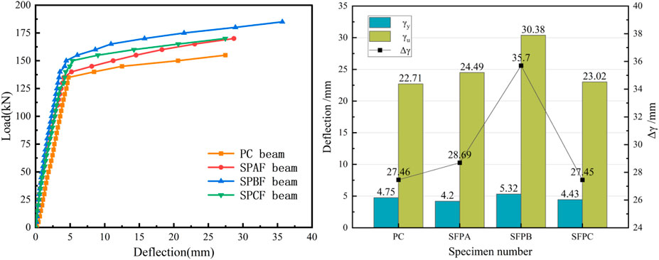
Figure 14. Load-deflection and deflection change curve.
From the overall view of the figure, the mid-span deflection growth of the test beam is mainly divided into two stages. Before the tensile longitudinal reinforcement reaches yield, the deflection increases linearly and slowly. The mid-span deflection of the SPBF test beam changes the most slowly with the increase of load, and the mid-span deflection is the least under the same load. Taking the load of 150 kN as an example, the deflection of SFPB is only 25.8% of PC, which shows that the action of this hybrid fiber has a significant improvement effect on the deflection of the beam. When the load increases to a certain extent, the yield of the tensile longitudinal reinforcement and the bearing capacity of the member do not change obviously, but the mid-span deflection and crack width increase sharply. PC, SPAF, SPCF, and SPBF are listed in the order of the growth inflection point. When the member reaches the ultimate load, the mid-span deflection of the SPBF beam is 35.7 mm, and that of the PC test beam is 27.46 mm, which indicates that PBF raises the ultimate load of the concrete beam while increasing the stiffness of the member and reducing the deformation of the member.
In addition, the deflection at the yield of the longitudinal bar is measured as γy, and the corresponding deflection at the ultimate load is recorded as γu, The difference between γy and γu is denoted by
4.3.3 Load-strain
Figure 15 shows the relationship between concrete strain and load. Through the analysis of the figure, it can be deduceed that when the load reaches 100 kN, only the last two effective strain gauges of the PC beam are still working normally, while the number of effective strain gauges of other test beams is 3, 4, and 5 respectively, indicating that the damage of PC beam is relatively serious compared with that of fiber concrete beam. In addition, the measuring points with the same cross-section height of each beam are selected as the research object, and the strain size of each beam under the same load is compared and analyzed. The corresponding strain of the measuring point 150 mm away from the bottom of the beam when the load is 80 kN is taken as an example: The strain of the PC beam is 2594.42με, SPAF beam is 1534.06με, SPBF beam is 1279.22με, and SPCF beam is 882.64με. The strain of hybrid fiber concrete beams is much smaller than that of ordinary concrete beams, which indicates that the elastic modulus and stiffness of the test beams increase and the ability to resist deformation is enhanced.
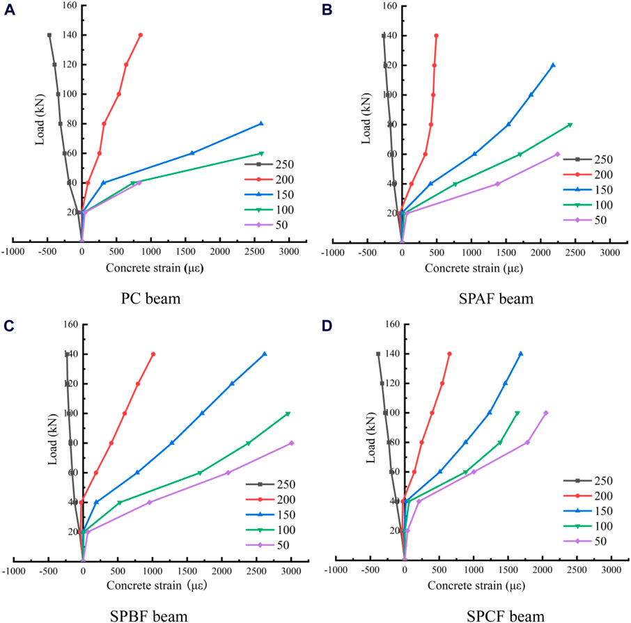
Figure 15. Load - concrete strain. (A) PC beam (B) SPAF (C) SPBF (D) SPCF.
Figure 16 shows the relationship between reinforcement strain and load. The last set of data before the failure of the reinforcement strain gauge was selected for drawing and analysis. Among them, the R1 strain gauge in the PC group and the L1 and R1 strain gauge in the SPCF group were not included in the analysis due to the failure caused by damage.
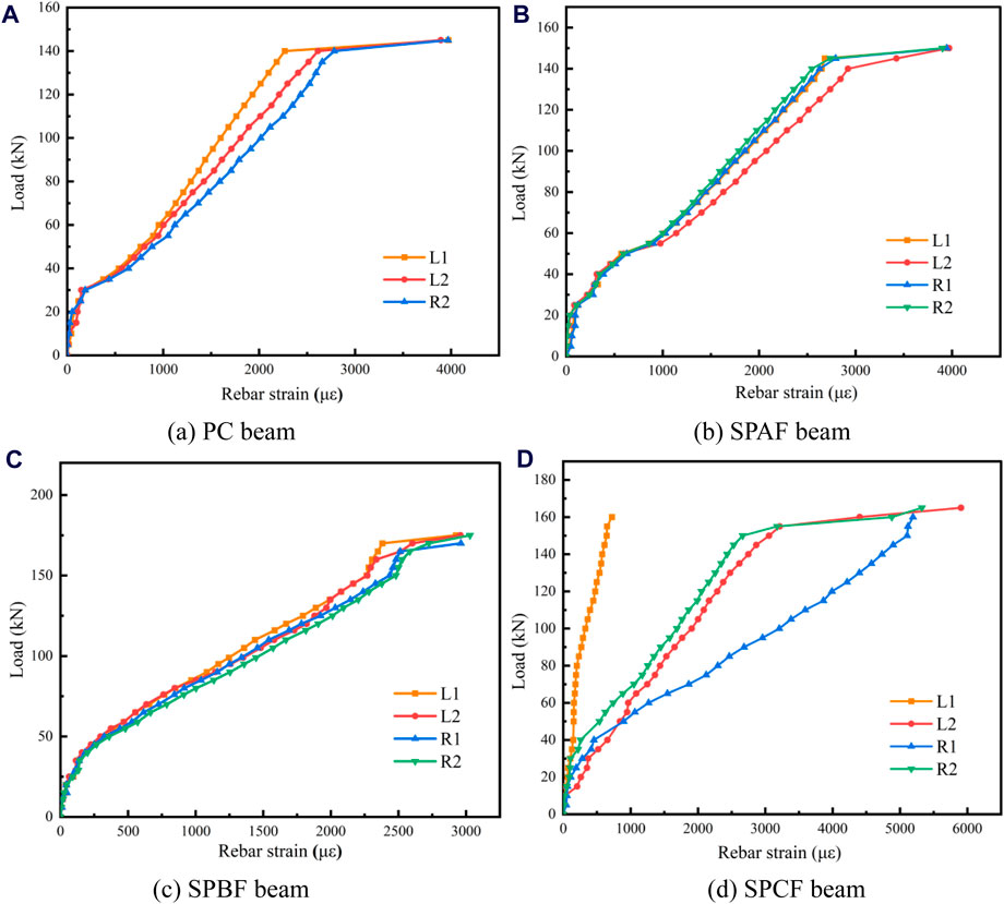
Figure 16. Load - Strain of reinforcement. (A) PC beam (B) SPAF (C) SPBF (D) SPCF.
As a whole, the strain rise of longitudinal reinforcements of each beam for the test can be roughly divided into three stages. In the first stage, the concrete is in the elastic stage, and the strain growth of the longitudinal reinforcements is not obvious with the load. The second stage is the stage of uniform increase of longitudinal reinforcement strain after concrete cracking, during which the tensile stress is primarily borne by the longitudinal reinforcement. The third stage begins when the longitudinal reinforcement reaches the yield strength. At this time, the cross-section of the longitudinal reinforcement becomes smaller, and load growth is not obvious, but the stress and strain at the weak position of the tensile longitudinal reinforcement increase rapidly. Soon, the longitudinal reinforcement breaks, and the deflection and cracks of the concrete develop rapidly.
The transverse comparison of the data of four test beams can analyze the improvement effect of different hybrid fibers on different levels of concrete properties. First of all, comparing the load corresponding to the turning point of the first and second stages, the index can reflect the level of concrete tensile performance, PC test beam, SPAF beam, SPBF beam, and SPCF beam are 30, 40, 50, and 40 kN respectively, which can preliminarily conclude that SPBF test beam performance is better. Secondly, the load when the tensile longitudinal reinforcement reaches the yield strength can reflect the difference in the energy absorption capacity of hybrid fiber in the process of the test load.
Beam with the lowest index is 140 kN for the PC beam, and the beam with the highest index is 170 kN for the SPBF beam, and the lifting amplitude is 21.4%. In addition, the data of each strain gauge of the load-reinforcement strain curve of the SPBF beam are less discrete, and the transition between the first and second stages is smooth, which further proves the excellent performance of SPFRC and reinforcement working together. In conclusion, the SPBF beam is the best test beam in terms of load-reinforcement strain analysis.
4.3.4 Flat section assumption
The variation of concrete strain with load is verified by the strain data collected by the concrete strain gauge arranged equidistant along the height direction in the beam span. The strain data are collected every 20 kN, and the data are drawn into line charts Figure 17 for easy analysis.
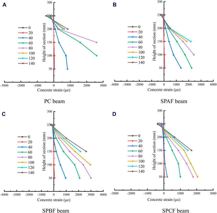
Figure 17. Strain variation of concrete with different section heights. (A) PC beam (B) SPAF (C) SPBF (D) SPCF.
Through the analysis of the law in the figure, it can be seen that the concrete strain of each group of beams always changes linearly along the height direction before cracking, which accords with the assumption of plain section. With the increase in load, cracks at the bottom of the beam gradually rise. The strain data at the bottom of the PC beam reaches 60 kN, there is a large fluctuation, and the compression zone is basically in line with the assumption of a plain section. Under the same conditions, the SPFRC beam can still maintain a better linear relationship, and the tension zone and the compression zone are in line with the assumption of a plain section.
Consistent with the crack development in Figure 13, most of the strain gauges of PC beams have been damaged and withdrawn from work when they are about 100 kN, and the data of SPFRC beams under the same load are still in the effective range. It shows that hybrid fibers can share part of the tensile load and alleviate the situation of stress concentration in the tensile area of concrete. Compared with PC beams, SPBF beam has a smaller compression zone height, mainly because the fiber can not only enhance the tensile strength of concrete but also improve the compressive strength of the concrete matrix, which can reduce the strain of the concrete in the compression zone to a certain extent, thereby improving the bending performance of the beam.
5 Conclusion
In this paper, the macroscopic mechanical properties and microstructure of SPFRC materials were tested, and the hybrid effect of fibers and the energy dissipation mode of fibers were analyzed. The strengthening effects of different hybrid fiber combinations on the bearing properties of beam members are also investigated. The main conclusions are as follows:
(1) In the case of single-shear SF reinforced concrete, the compressive strength and flexural strength of concrete at 1.0% are the best, which are 29.9% and 17.7% higher than PC, respectively.
(2) The mechanical properties of SPFRC are better than those of PC and single fiber concrete. The mechanical strength of hybrid fiber concrete with 1.0% SF and 0.14% PAF volume content is the highest. The compressive strength and flexural strength of hybrid fiber concrete with SF content of 1.0% and PBF volume content of 0.6% are the highest. The compressive strength and splitting tensile strength of hybrid fiber concrete with SF content of 1.0% and PCF volume content of 0.11% are the highest.
(3) Through SEM scanning, the SF surface is rough, which can increase the contact area with the concrete matrix. The surface pattern and wavy shape of PF can increase the moisture adhesion on the surface of the fiber per unit length, enhance the bonding effect, and reduce the weakening effect on compactness. In addition, the space skeleton formed by interleaving and overlapping hybrid fibers can improve the strength of concrete. In addition, the energy consumption of SF and PCF is fiber fracture and fiber pull-out, while PAF and PBF are mainly fracture energy consumption.
(4) Compared with PC beams, the initial crack load and ultimate load of SPFRC beams are significantly improved, among which SPBF beams have the most obvious increase, the ultimate load reaches 185 MPa, and the increase rate is 19.35% compared with PC beams. The SPBFRC beams have the best deformation resistance. In addition, the fiber can not only bear part of the tensile stress to delay the yield of the steel bar but also effectively improve the compressive and tensile properties of concrete.
In summary, the hybrid combination of SF with a volume content of 1.0% and embossed PF with a volume content of 0.6% can be used as the optimal scheme for mechanical properties and flexural properties of SPFRC beam members.
Data availability statement
The original contributions presented in the study are included in the article/supplementary material, further inquiries can be directed to the corresponding author.
Author contributions
JLi: Resources, Supervision, Writing–review and editing. JLu: Conceptualization, Software, Writing–original draft. LC: Data curation, Investigation, Methodology, Writing–review and editing. XF: Software, Validation, Writing–original draft. YZ: Formal Analysis, Visualization, Writing–original draft. XW: Visualization, Writing–original draft. JG: Project administration, Writing–original draft.
Funding
The author(s) declare that financial support was received for the research, authorship, and/or publication of this article. This project is financially supported by the Science and Technology Development Plan of Jilin Province (20210203178SF) and (YDZJ202302CXJD052).
Conflict of interest
Author JG was employed by Shenyang Nonferrous Metallurgy Design and Research Institute Co., LTD.
The remaining authors declare that the research was conducted in the absence of any commercial or financial relationships that could be construed as a potential conflict of interest.
Publisher’s note
All claims expressed in this article are solely those of the authors and do not necessarily represent those of their affiliated organizations, or those of the publisher, the editors and the reviewers. Any product that may be evaluated in this article, or claim that may be made by its manufacturer, is not guaranteed or endorsed by the publisher.
References
Abbadi, A., Basheer, P. A. M., and Forth, J. P. (2022). Effect of hybrid fibres on the static load performance of concrete beams. Mater. Today Proc. 65, 681–687. doi:10.1016/j.matpr.2022.03.263
Abed, S., Hadi, R., Jawdhari, A., Mohammed Najm, H., Mahmood, S., Bilema, M., et al. (2023). Influence of ternary hybrid fibers on the mechanical properties of ultrahigh-strength concrete. Front. Mater. 10, 1148589. doi:10.3389/fmats.2023.1148589
Abousnina, R., Premasiri, S., Anise, V., Lokuge, W., Vimonsatit, V., Ferdous, W., et al. (2021). Mechanical properties of macro polypropylene fibre-reinforced concrete. Polymers 13, 4112. doi:10.3390/polym13234112
Ahanger, S., and Tiwary, A. K. (2024). Steel fiber’s effect on the mechanical properties of concrete with recycled aggregate. Mater. Today Proc. doi:10.1016/j.matpr.2024.01.028
Awad, A., Tawfik, M., Deifalla, A., Ahmad, M., Sabri Sabri, M. M., and El-said, A. (2023). Effect of hybrid-fiber-reinforcement on the shear behavior of high-strength-concrete beams. Front. Mater. 9, 1088554. doi:10.3389/fmats.2022.1088554
Bhogone, M. V., and Subramaniam, K. V. L. (2022). Improvement in early-age cracking performance of concrete with hybrid steel-macropolypropylene fiber blends. Mater. Today Proc. 65, 1589–1593. doi:10.1016/j.matpr.2022.04.554
Dash, B., Giri, J. P., Raju, P. M., and Dora, D. (2023). Simultaneous influence of processed cellulose acetate fiber reinforcement and recycled aggregate replacement on mechanical and durability performances of concrete. Constr. Build. Mater. 401, 132950. doi:10.1016/j.conbuildmat.2023.132950
Ding, D., Zhang, L., Zhao, J., and Wang, Z. (2022). Effects of air-entraining agent and polypropylene fiber on the mechanical properties, autogenous shrinkage, and fracture properties of fully recycled aggregate concrete. Front. Mater. 9, 1049304. doi:10.3389/fmats.2022.1049304
GB/T 50081-2019 (2019). Standard for test methods of concrete physical and mechanical properties [S]. Beijing: China Architecture and Construction Press. (in chinese).
GB/T50152-2012 (2012). Standard for test method of concrete structures [S]. Beijing: China Architecture and Construction Press. (in chinese).
He, X. (2002). Experimental study on high performance concrete with low content steel fiber/polypropylene fiber [D]. Dalian University of Technology. (in chinese).
JGJ55-2011 (2011). Specification for mix proportion design of ordinary concrete [S]. Beijing: China Building and Construction Press. (in chinese).
Khan, M., Cao, M., Xie, C., and Ali, M. (2022). Effectiveness of hybrid steel-basalt fiber reinforced concrete under compression. Case Stud. Constr. Mater. 16, e00941. doi:10.1016/j.cscm.2022.e00941
Kun, L., Xin, L. H., Bei, L. B., and Nan, L. Y. (2023). Mechanical performance and carbonation resistance of basalt fiber—polypropylene fiber rubber concrete. Front. Mater. 10, 1229629. doi:10.3389/fmats.2023.1229629
Li, J., Chen, L., Luo, J., Zhu, W., Fan, X., Zhu, Y., et al. (2023a). Mechanical properties and microscopic characteristics of steel fiber coal gangue concrete. Front. Mater. 10, 1211129. doi:10.3389/fmats.2023.1211129
Li, J., Chen, L., Luo, J., Zhu, Y., Fan, X., and Hu, G. (2023b). Study on mechanical properties and microstructure of steel-polypropylene fiber coal gangue concrete. Front. Mater. 10, 1281372. doi:10.3389/fmats.2023.1281372
Li, J., Chen, L., Wang, X., Hu, G., Wang, Z., Guo, J., et al. (2023d). Effect of compounding conductive materials on the mechanical properties of concrete and the microscopic mechanism. Constr. Build. Mater. 377, 131000. doi:10.1016/j.conbuildmat.2023.131000
Li, J., Fan, X., Luo, J., Zhu, Y., Chen, L., and Wang, X. (2023c). Effect of Steel fiber type and content on Mechanical properties of concrete. J. Xinxiang Univ. 40 (09), 49–52. (in chinese).
Li, J., Fan, X., Luo, J., Zhu, Y., Wang, X., Guo, J., et al. (2024b). Mechanical properties test of polypropylene fiber concrete. J. Liaoning Normal Univ. 26 (01), 103–108. (in chinese).
Li, J., Luo, J., Chen, L., Fan, X., Zhu, Y., and Wang, X. (2024a). Axial-compression performance and numerical-simulation analysis of steel tube coal gangue concrete column. J. Constr. Steel Res. 216, 108612. doi:10.1016/j.jcsr.2024.108612
Li, J., Luo, J., Li, C., Zhu, Y., Fan, X., Wang, X., et al. (2024c). Study on mechanical properties and freeze-thaw damage law of steel fiber coal gangue concrete. J. Build. Eng. 94, 110039. doi:10.1016/j.jobe.2024.110039
Li, J., Qin, Q., Sun, J., Ma, Y., and Li, Q. (2022). Mechanical and conductive performance of electrically conductive cementitious composite using graphite, steel slag, and GGBS. Struct. Concr. 23 (1), 533–547. doi:10.1002/suco.202000617
Lin, L., Shu, W., Xu, H., Rui, X., Wang, Z., Zeng, Y., et al. (2024). Experimental study on flexural toughness of fiber reinforced concrete beams: effects of cellulose, polyvinyl alcohol and polyolefin fibers. J. Build. Eng. 81, 108144. doi:10.1016/j.jobe.2023.108144
Liu, F., Xu, K., Ding, W., Qiao, Y., and Wang, L. (2021). Microstructural characteristics and their impact on mechanical properties of steel-PVA fiber reinforced concrete. Cem. Concr. Compos. 123, 104196. doi:10.1016/j.cemconcomp.2021.104196
Liu, W., and Han, J. (2019). Experimental investigation on compressive toughness of the PVA-steel hybrid fiber reinforced cementitious composites. Front. Mater. 6, 108. doi:10.3389/fmats.2019.00108
Muhyaddin, G. F. (2023). Mechanical and fracture characteristics of ultra-high performance concretes reinforced with hybridization of steel and glass fibers. Heliyon 9 (7), e17926. doi:10.1016/j.heliyon.2023.e17926
Qing, L., Nie, Y., and Mu, R. (2017). Effect of steel fiber on crack resistance of cement-based composites. J. Compos. Mater. 34 (08), 1862–1869. (in chinese).
Ramadoss, P., Li, L., Fatima, S., and Sofi, M. (2023). Mechanical performance and numerical simulation of high-performance steel fiber reinforced concrete. J. Build. Eng. 64, 105424. doi:10.1016/j.jobe.2022.105424
Sahoo, D. R., Solanki, A., and Kumar, A. (2015). Influence of steel and polypropylene fibers on flexural behavior of RC beams. J. Mater. Civ. Eng. 27 (8), 04014232. doi:10.1061/(asce)mt.1943-5533.0001193
Shashikumara, S. R., Pramukh, N., Abhishek, R., and Nagaraj, V. (2023). Experimental study on the influence of polypropylene and steel fiber on flexural behaviours of high strength concrete beams. Mater. Today Proc. 88, 85–92. doi:10.1016/j.matpr.2023.05.020
Song, P. S., and Hwang, S. (2004). Mechanical properties of high-strength steel fiber-reinforced concrete. Constr. Build. Mater. 18 (9), 669–673. doi:10.1016/j.conbuildmat.2004.04.027
Sun, J., Wang, Y., Li, K., Yao, X., Zhu, B., Wang, J., et al. (2022). Molecular interfacial properties and engineering performance of conductive fillers in cementitious composites. J. Mater. Res. Technol. 19, 591–604. doi:10.1016/j.jmrt.2022.05.061
Vedernikov, A., Minchenkov, K., Gusev, S., Sulimov, A., Zhou, P., Li, C., et al. (2022). Effects of the pre-consolidated materials manufacturing method on the mechanical properties of pultruded thermoplastic composites. Polymers 14 (11), 2246. doi:10.3390/polym14112246
Wang, C., and Wu, K. (2002). Effect of fiber with different elastic modulus on mechanical properties of high strength concrete. Concr. Cem. Prod. (03), 36–37. (in chinese).
Xian, G., Bai, Y., Zhou, P., Wang, J., Dong, S., Guo, R., et al. (2024b). Long-term properties evolution and life prediction of glass fiber reinforced thermoplastic bending bars exposed in concrete alkaline environment. J. Build. Eng. 91, 109641. doi:10.1016/j.jobe.2024.109641
Keywords: steel fiber, polypropylene fiber, hybrid fiber concrete, mechanical properties, concrete beam
Citation: Li J, Luo J, Chen L, Fan X, Zhu Y, Wang X and Guo J (2024) Research on mechanical properties of steel-polypropylene fiber concrete and application of beam structure. Front. Mater. 11:1440466. doi: 10.3389/fmats.2024.1440466
Received: 29 May 2024; Accepted: 18 July 2024;
Published: 06 August 2024.
Edited by:
Giulio Alfano, Brunel University London, United KingdomReviewed by:
Nor Hafizah Binti Ramli, Queensland University of Technology, AustraliaChenggao Li, Harbin Institute of Technology, China
Copyright © 2024 Li, Luo, Chen, Fan, Zhu, Wang and Guo. This is an open-access article distributed under the terms of the Creative Commons Attribution License (CC BY). The use, distribution or reproduction in other forums is permitted, provided the original author(s) and the copyright owner(s) are credited and that the original publication in this journal is cited, in accordance with accepted academic practice. No use, distribution or reproduction is permitted which does not comply with these terms.
*Correspondence: Jingwei Luo, Mjg0ODQxNTM1OEBxcS5jb20=