
95% of researchers rate our articles as excellent or good
Learn more about the work of our research integrity team to safeguard the quality of each article we publish.
Find out more
ORIGINAL RESEARCH article
Front. Mater. , 22 August 2024
Sec. Polymeric and Composite Materials
Volume 11 - 2024 | https://doi.org/10.3389/fmats.2024.1437104
This article is part of the Research Topic Development of High-Performance Resin Matrix Composites - Volume II View all 4 articles
 Xinfeng Ouyang1Guojie Ge2Yizhi Geng1Yangyang Zong1Tong Pan2Xiao Wang2Weiwei Zhu2
 Yuefeng Bai1
 Yunpeng Liu1Shuo Duan1
 Kangmin Niu1*
The present study involves the preparation of continuous carbon fiber samples treated with epoxy-based sizing agent (EP) and vinyl ester resin-based sizing agent (VE), alongside untreated fibers, aiming to explore the influence pattern of interfacial differences caused by these sizing agents on the compressive properties of carbon fiber composites. Surface analysis, including Scanning Electron Microscope (SEM), Atomic Force Microscope (AFM), and X-ray Photoelectron Spectroscopy (XPS), followed by testing the mechanical properties of carbon fibers and the composite materials. Results indicate that, compared to unsized carbon fibers, EP and VE increase the O atom content on the carbon fiber surface by 13.0% and 18.1%, respectively, and enhance the proportion of active C atoms by 11.3% and 20.3%, respectively. The interlaminar shear strength (GB/T) of carbon fibers is improved by 9.3% and 20.0%, respectively. Given the compatibility between the sizing agent and the matrix resin, VE improves the open-hole compressive strength of composites by 6.7% compared to EP. This improvement in interface bonding performance positively impacts the open-hole compressive properties of the composites, though it has limited effect on the 0° compressive and post-impact compressive strengths. Following EP and VE sizing, the 0° compressive strength increases by 11.8% and 13.6%, respectively, with VE only resulting in a marginal 1.6% improvement over EP. The enhancements in both interlaminar shear strength and open-hole compressive strength are attributed to the increased number of active functional groups at the fiber-resin interface, facilitated by sizing agents, which promote stronger chemical bonding and thus improved load transfer between the fibers and the matrix. VE demonstrates superior performance over EP in regulating the interface state of carbon fibers.The presence or absence of a sizing agent has a more significant impact on the compressive properties of carbon fiber composites than the type of sizing agent used. These findings provide valuable insights for optimizing the preparation and enhancing the compressive performance of carbon fiber composite materials.
Carbon fiber reinforced resin-based composite materials, due to their superior mechanical properties, corrosion resistance, fatigue resistance, and creep resistance, have been widely applied in modern industrial systems such as aerospace, wind power, photovoltaic, and new energy vehicles, becoming one of the most important materials in the field of new materials (He, 2010; Li et al., 2019). However, the mainstream dry-jet wet spinning carbon fibers have smooth and inert surfaces, resulting in a weak interface between the carbon fiber and the resin. This weak interface causes interface delamination during the application of composite materials, thereby affecting the performance of carbon fiber composite materials (Totry et al., 2010). Currently, there are two main methods to improve the interface of carbon fiber resin-based composite materials. One method is to treat the surface of the carbon fiber itself, such as using anodic electrochemical oxidation treatment (Zhang, 2010; Wu, 2017), plasma sputtering treatment, surface electrophoresis coating or grafting treatment (Deng et al., 2015; Jiang et al., 2015; Deng et al., 2016; Gao et al., 2016; Xiong et al., 2023), which involve physical or chemical methods to treat the surface of the carbon fiber. Anodic electrochemical oxidation is the most mature method used in industry for surface modification. Another method involves introducing a sizing agent layer between the carbon fiber and the resin, utilizing the bridging effect of the sizing agent layer to connect the fiber surface internally and the resin matrix externally (Guo et al., 2012; Hao et al., 2016), thereby enhancing the interface properties of the carbon fiber resin-based composite material. Current research on carbon fiber sizing agents focuses on altering the type of sizing agents, modifying them, or doping them with additives (Chen et al., 2011; Liu, 2012; Zhang et al., 2013; Xingyao et al., 2016; Zhang et al., 2016; Yuan et al., 2017; Zhao et al., 2017; Guang et al., 2019; Wang et al., 2022). Carbon nanotubes, graphene oxide, silica, and other materials are commonly used as additives (Zhang et al., 2007; Zhao, 2017; Wu et al., 2018; Biswas et al., 2023; Geng et al., 2023).
High-performance carbon fiber composite materials represented by T800-grade carbon fibers have always faced the challenge of poor impact resistance and compressive strength far lower than tensile strength during application, which severely restricts the performance and application of high-performance carbon fiber (Nunna et al., 2023). Currently, many scholars have conducted a series of studies focusing on the low compressive performance of carbon fiber composites, primarily examining three aspects: carbon fiber body, matrix resin, and the interface layer between fiber and resin. Research on carbon fiber bodies focuses on fiber diameter, fiber compressive strength, microcrystal size, core-shell structure, etc. (Li et al., 2018; Wenmo, 2019; Jia, 2020; Lu Gan, 2020; Zhu et al., 2020; Shi et al., 2021; Wang, 2021), while research on matrix resins focuses on graft modification, doping modification, etc. (Qi et al., 2006; Subramaniyan and Sun, 2006; Fu et al., 2008; Marouf, 2009; Marouf et al., 2009; Young et al., 2012; Marouf et al., 2016). Taking carbon fiber epoxy resin-based composite materials prepared by Japan’s Toray Industries as an example, when carbon fibers change from T300 to T1100, their tensile strength nearly doubles while the compressive strength remains almost unchanged (Toray Industries, 2023). Therefore, improving the tensile performance of carbon fibers cannot effectively solve the problem of low compressive strength of carbon fiber composite materials. Currently, scholars generally agree that there are four types of compressive failure modes in carbon fiber composites: shear, interlaminar, interfacial, and kink-band failure (Nunna et al., 2023). The interfacial delamination caused by the weak interface between carbon fiber and resin is considered one of the important factors leading to shear and interlaminar damage due to compression instability (Prabhakar and Waas, 2013). Although the use of sizing agents to improve the interfacial performance of carbon fiber composites has become a research hotspot, most current studies focus on the improvement of interfacial performance of carbon fiber composites by sizing agents, concentrating on changes in interlayer shear strength or interfacial shear strength of carbon fiber. However, few studies have examined the practical application of sizing agents and their impact on the performance of carbon fiber composites, especially compressive performance. This paper commences from the perspective of industrial applications, preparing two sizing agents, EP and VE. Through adjusting the molecular structure types of the sizing agents, it modulates and characterizes the functional group states on the surface of carbon fibers. The paper delves into the correlation between the type of sizing agent and the surface properties of carbon fibers. Furthermore, it establishes the impact pattern of the sizing agents on the compression strength of carbon fiber composite materials.
The two sizing agents, EP and VE, used in the experimental process are homemade, water-based white emulsions, with a solid content of 40%. Among them, VE contains a certain proportion of EP.
The volume average particle sizes of EP and VE are 0.645 μm and 0.632 μm respectively. The temperatures at which 50% weight loss occurs are 378.8°C and 389.2°C respectively. The peak exothermic temperatures are 465.4°C and 467.1°C respectively. Both are stable after standing for 72 h at 10°C and 60°C. No precipitation occurs after centrifugation at 4,000 rpm for 5 min.
Wet winding machine, Jiangsu Yingyou Spinning Machinery Co., Ltd.; Hot press tank, Shandong Zhonghang Taida Composite Materials Co., Ltd. R2021-0011; Tensile testing machine, Shimadzu Corporation AG-XPLUS; Precision milling machine, Qiaoke CNC Machinery Equipment Co., Ltd. QK6090-1; Hot air circulation drying oven, Suzhou Deripu Oven Manufacturing Co., Ltd. DRP-8803; Vernier caliper, Sata Tools (Shanghai) Co., Ltd. SATA 91511.
Adjacent positions on the Zhongfu Shenying SYT55-12K production line were utilized to collect 12K continuous carbon fiber tows treated with sizing agents EP and VE (control the content of sizing agent at 1% ± 0.3% (Ouyang et al., 2016; Xinfeng et al., 2018)), denoted as EP-CCF and VE-CCF respectively, as well as unsized carbon fiber tows denoted as US-CCF. The wet winding machine was employed to prepare samples of US-CCF, EP-CCF, and VE-CCF into wet prepregs. The resin used was WP-S5100 from Huibao New Material Technology (Shanghai) Co., Ltd., with a resin content of 40% and a surface density of 200 g/m2. Carbon fiber composite laminates were then fabricated using a hot press tank. The hot press tank process involved vacuuming at room temperature to achieve a vacuum pressure of −0.090 to −0.098 MPa inside the vacuum bag. Pressure was then gradually increased at a rate of 0.02 MPa/min until reaching 0.6 MPa. Subsequently, the temperature was raised at a rate of 1.5 C/min to 70°C and maintained for 70 min, followed by a further temperature increase at the same rate to 130°C and maintained for 130 min. Finally, pressure was gradually reduced at a rate of 1.5 C/min, and the temperature was lowered to below 60°C before depressurizing the tank. The laminates were then machined to the required dimensions using a precision milling machine, and the desired test specimens were obtained. The key steps of the experimental process are shown in Figure 1.
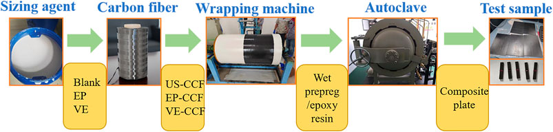
Figure 1. Illustration of key steps in the experimental content.
The surface morphology of carbon fibers and the fracture surface of composite materials under compression were observed using a Field Emission Scanning Electron Microscope (Hitachi REGULUS series SU8100). The surface elemental composition of carbon fibers was analyzed using an X-ray Photoelectron Spectrometer (Shimadzu/Kratos, AXIS SUPRA model). The radiation source was Al K alpha, and the spot size was 500 µm. The atomic percentage was calculated using the formula n1/n2 = (S1/L1)/(S2/L2) by fitting the area ratio, where n represents the number of atoms, S represents the integrated area, and L represents the sensitivity factor (obtained from a database). The three-dimensional morphology distribution of carbon fiber surfaces was characterized using a Bruker Dimension ICON Atomic Force Microscope operating in tapping mode with a scan size of 2 µm and a scan rate of 1 Hz. The contact angle was measured using a Swedish Biolin Scientific Attension Theta Flex optical contact angle meter, with a measurement range of 0°–180°. The testing was conducted using the sessile drop method, and the test liquid used is the specialized epoxy resin EW-800-1S, produced by Beijing Yihuachengda Technology Co., Ltd.
The density is determined according to GB/T 30019-2013. Filament tensile strength, Young’s modulus, and elongation at break were determined according to GB/T3362-2005 (the number of samples is 6). The interlaminar shear strength of carbon fiber was measured following the method outlined in GB/T 1450.1-2005 (wrapping plate method, the number of samples is 5). The tensile strength of individual carbon fiber filaments was determined in accordance with GB/T31290-2014 (the number of samples is 60). The sizing content was measured using the Soxhlet extraction method outlined in Method A of GB/T 29761-2013 (the number of samples is 3). All testing procedures were conducted at a temperature of 25°C ± 1°C and an ambient humidity of <40%.
The 0° tensile strength and 0° tensile modulus were determined according to ASTM D3039/D3039M-2014, which is the standard test method for tensile properties of polymer matrix composite materials. The 0° compressive strength and 0° compressive modulus were measured in accordance with ASTM D6641/D6641M-16ε2, using the combined loading compression (CLC) fixture, which is the standard test method for determining compressive properties of polymer matrix composite materials. Compression After Impact (CAI) was assessed by combining ASTM 7136/D7136M-20, which is the standard test method for measuring the damage resistance of fiber-reinforced polymer matrix composites to drop-weight impact events, and ASTM D7137/D7137M-17, which is the standard test method for compressive residual strength properties of damaged polymer matrix composite plates. A semi-spherical steel impactor with a diameter of ϕ16 mm was used, and the impact energy was adjusted to 6.7 J/mm. The dimensions of the specimen were 150 mm × 100 mm × 4.5 mm. The impact energy was calculated as 4.5 mm × 6.7 J/mm = 30.15 J. Open hole tensile strength (OHT) was evaluated following ASTM D5766/D5766M-2011, which is the standard test method for tensile strength of polymer matrix composite laminates with open holes. The specimen size for open hole tension testing was 300 mm × 36 mm × 3 × ϕ6 mm. Open hole compressive strength (OHC) was assessed according to D6484/D6484M–2014, which is the standard test method for compressive strength of polymer matrix composite laminates with open holes. Interlaminar shear strength (ILSS) was measured following ASTM D2344/D2344M-2016, which is the standard test method for short-beam shear strength of polymer matrix composite materials and their laminates. The environmental conditions for ILSS testing were as follows: a) Room Temperature Dry (RTD) testing: specimens were conditioned in an environment with a temperature of 23°C ± 3°C and a relative humidity of 50% ± 10% for at least 24 h; b) Elevated Temperature Dry 1 (ETD1) testing: the test temperature was 82°C, and the specimens should reach the test temperature within 5 min of installation and be tested 2–3 min after reaching the test temperature; c) Elevated Temperature Dry 2 (ETD2) testing: the test temperature was 120°C, and the specimens should reach the test temperature within 5 min of installation and be tested 2–3 min after reaching the test temperature. The number of samples tested for the composite materials is five valid specimens.
The samples were subjected to XPS testing, and the full spectrum is shown in Figure 2 (left). Peak fitting was performed in the range of 950–50 eV to obtain the peak area of each atom and calculate the atomic composition. At 285 eV, the C1s peak is observed for carbon, the O1s peak is observed at 533 eV for oxygen, the N1s peak is observed at 400 eV for nitrogen, and the Si2s and Si2p peaks are observed at 102 eV and 152 eV, respectively, for silicon. The surface atomic composition percentages of the samples are listed in Table 1. For the untreated US-CCF sample, the carbon atomic composition reaches 92.40%, and the oxygen atomic composition is 4.40%. In the EP-CCF and VE-CCF samples, the carbon atomic composition is 81.93% and 77.06%, respectively, while the oxygen atomic composition is 17.35% and 22.50%, respectively. It can be observed that the carbon atomic composition on the carbon fiber surface significantly decreases after the application of sizing agents, while the oxygen content significantly increases. This is because the sizing agents contribute to the oxygen content with epoxy, ether, and ester groups, significantly altering the atomic composition and functional groups on the carbon fiber surface.
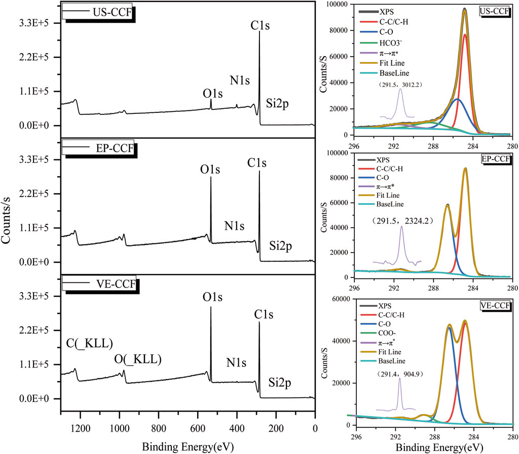
Figure 2. XPS full spectrum (left) and C1s fitting diagram (right) of carbon fiber samples.
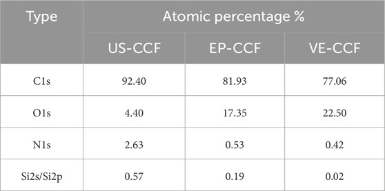
Table 1. Distribution of major atomic contents on the surface of carbon fiber samples.
The sample US-CCF represents the surface state of carbon fiber after surface treatment. Due to the water washing process, the number of active functional groups is limited, mainly composed of the C element from the carbon fiber matrix. The C atom ratio accounts for 92.4%. The O atoms on the surface of carbon fiber originate from the reaction between Si in the precursor oil agent and O in the air during the process to produce silicon oxide compounds, hydroxyl or carboxyl groups formed by electrochemical surface treatment, and O-containing functional groups in the sizing agent after sizing. The Si atoms come from the precursor oil agent, which continuously decomposes and sheds after the pre-oxidation and carbonization processes, but there is still Si residue in the skin layer on the surface of carbon fiber. The N atoms come from the residual N element in the precursor, amide groups formed in the NH4HCO3 electrolyte during electrochemical surface treatment (Prabhakar and Waas, 2013), and nitrogen-silicon compounds generated by the reaction between Si in the oil agent and the protective nitrogen gas during the low- and high-temperature carbonization stages. After the sizing process, the original surface of carbon fiber is coated with carbon fiber sizing agent, resulting in a significant reduction in the detected content of Si and N elements compared to the US-CCF sample. The Si content of EP-CCF and VE-CCF is 0.19% and 0.02%, respectively, while the N content is 0.53% and 0.42%, respectively.
Further analysis was conducted on the C1s spectrum of the samples through peak fitting, as shown in Figure 2 (right). The possible forms of carbon atoms include C-C/C-H, C-O, HCO3-, COO-, and the π→π* transition peak of the benzene ring. The calculation results are presented in Table 2. After sizing, the proportion of active carbon atoms on the carbon fiber surface increased from 27.27% in the unsized sample to 38.55% and 47.53%, respectively, representing an increase of 11.28 and 20.26 percentage points. It is noted that the sizing agent VE outperforms EP in enhancing the surface activity of carbon fibers. A schematic diagram showing the main functional groups on the surface of carbon fibers based on the type of sizing agent is presented in Figure 3.
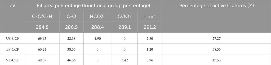
Table 2. The calculation results of the active carbon atom proportion obtained by fitting the C1S spectra of carbon fiber samples.
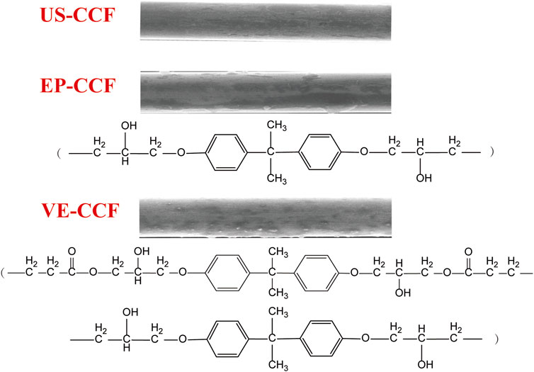
Figure 3. The main types of sizing agents used on the surface of carbon fibers. Schematic diagram of the distribution of active functional groups on different carbon fiber samples.
The contact angle test results for the carbon fiber samples are shown in Figure 4. The contact angles of the samples are all less than 90°, with the contact angle of the unsized sample US-CCF being 47.35°, and those of the sized samples EP-CCF and VE-CCF being 43.82° and 44.60°, respectively. The sizing agent increases the number of active functional groups on the surface of carbon fibers, thereby improving the wettability of the carbon fiber surface. The wettability of EP-CCF after sizing with EP is slightly better than that of VE-CCF after sizing with VE, and far superior to that of unsized US-CCF.
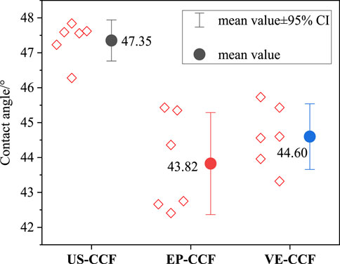
Figure 4. Contact angle test results of carbon fiber surface.
Figure 5 presents the results of high-magnification scanning electron microscope (SEM) observations of the carbon fiber samples. Figures 5A, C, E show the observation results of the corresponding samples at 5,000 times magnification, while Figures 5B, D, F show the observation results of the corresponding areas at 30,000 times magnification. Observing Figure 5A, the diameter of the carbon fibers in the US-CCF sample is approximately 5 μm, with a relatively smooth surface and no obvious deep grooves. Clear friction marks from the friction between the carbon fibers and the metal roller can be observed. From the 30,000 times magnification image in Figure 5B, a clear and uniform pattern is visible on the surface of the US-CCF, with fine lines distributed evenly, representing the original and real surface morphology of the carbon fibers. From Figures 5B–F, it can be seen that the surfaces of EP-CCF and VE-CCF after sizing exhibit a noticeable layer of sizing agent. The friction marks from the friction with the metal roller are significantly reduced, and there are larger sizing agent particles distributed on the surface. In the 30,000 times magnification image, it is evident that the particles on the surface of VE-CCF are slightly larger than those on EP-CCF, and the fine lines on the fiber surface after sizing agent coating are not visible.
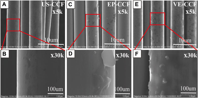
Figure 5. High-resolution SEM images of carbon fiber samples. (A,C,E) are SEM images under X5K magnification; (B,D,F) are SEM images under X30K magnification.
The root mean square (Rq) values of the roughness profiles along the vertical axis measured by atomic force microscopy for US-CCF, EP-CCF, and VE-CCF are 15.7 nm, 22.9 nm, and 43.1 nm, respectively. As seen in Figure 6, without sizing agent coating, US-CCF exhibits nano-scale, uniformly distributed groove morphology (Li and Xian, 2019a; Li and Xian, 2019b), with no significant protrusions of sizing agent particles, and a roughness Rq of 15.7 nm. After sizing agent coating, the nano-scale groove morphology disappears from the surfaces of EP-CCF and VE-CCF, replaced by prominent protrusions of sizing agent particles, along with the presence of large particle aggregates. The morphology of particles on sample VE-CCF appears larger and more pronounced than that on EP-CCF, suggesting slight aggregation of the multi-component sizing agent VE during mixing drying processes.
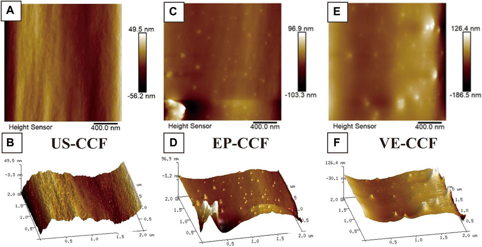
Figure 6. AFM Morphology of Carbon Fiber Surface. (A,C,E) are 2D AFM images; (B,D,F) are 3D AFM images.
The cross-sectional area for calculating the single-fiber strength is determined from the actual measurement of 5 μm in electron microscope photos. The number of samples is 60. The test results of single-fiber strength, along with the curve fitted to the statistical distribution of tensile force (gram-force value) for the samples, are shown in Figure 6.
Single-fiber strength is significantly influenced by sample preparation, fixtures, and human factors, resulting in strengths lower than those of multifilament yarns. The tensile strength of carbon fiber multifilaments strictly tests the tensile strength of the carbon fiber composite material, while the tensile strength of a monofilament directly measures the tensile strength of a single carbon fiber. The quality stability of the fiber itself can be revealed through the distribution function of monofilament strength. Carbon fibers without sizing agents exhibit slightly higher single-fiber strength compared to those treated with sizing agents. However, the tensile strength of unsized carbon fibers is notably lower, primarily due to the absence of considerations for the axial consistency between filaments within the multifilament yarns. Moreover, single fibers are inherently brittle, and the sizing agent layer becomes the initial fracture point under stress, acting as a source of failure. Consequently, carbon fibers with sizing agents may exhibit slightly lower single-fiber strength. Additionally, the microstructural and interfacial states of the sizing agent layer directly influence the mechanical properties of single fibers, making them more sensitive to various influencing factors. The experimental results suggest that the sizing agent layer does not positively contribute to the mechanical properties of single fibers (Wang et al., 2016) and may even induce fracture during tensile testing.
The results of multifilament yarn properties for carbon fiber samples are summarized in Table 3. The multifilament tensile strength of US-CCF is 5,596 MPa, while that of EP-CCF and VE-CCF is 6,124 MPa and 6,156 MPa, respectively. The loss of tensile strength in unsized multifilament is approximately 500 MPa, highlighting the crucial role of sizing agents in imparting strength. This indicates that sizing agents contribute positively and deterministically to ensuring filament consistency. Samples prepared without sizing agent coating exhibit further deterioration in filament-to-filament consistency, weakening their ability to contribute collectively to strength during tensile loading, resulting in lower multifilament tensile strength. The moduli of the carbon fiber samples are generally at the same level, with no effect from the presence or absence of sizing agents. Based on the results of interlaminar shear strength measured by GB/T method, the interlaminar shear strength of unsized carbon fibers is 108 MPa. After sizing, the interlaminar shear strength significantly increases, with VE-CCF and EP-CCF showing improvements of 9.3% and 20.0%, respectively, compared to US-CCF. This improvement is mainly attributed to the increased number of active functional groups and chemical bonding sites in the sizing agents, leading to enhanced van der Waals forces, thereby increasing the interlaminar shear strength.
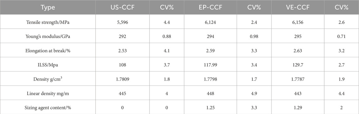
Table 3. The test results of carbon fiber properties.
The comparison of multifilament tensile strength,single-fiber tensile strength, and composite tensile strength is shown in Figure 7D and Table 4. The poor filament consistency of unsized bundles results in approximately 10% loss in multifilament tensile strength and approximately 8% loss in composite tensile strength. Comparison reveals that the tensile strength of carbon fiber composites and single fibers is approximately 43% and 75% of the multifilament tensile strength, respectively.
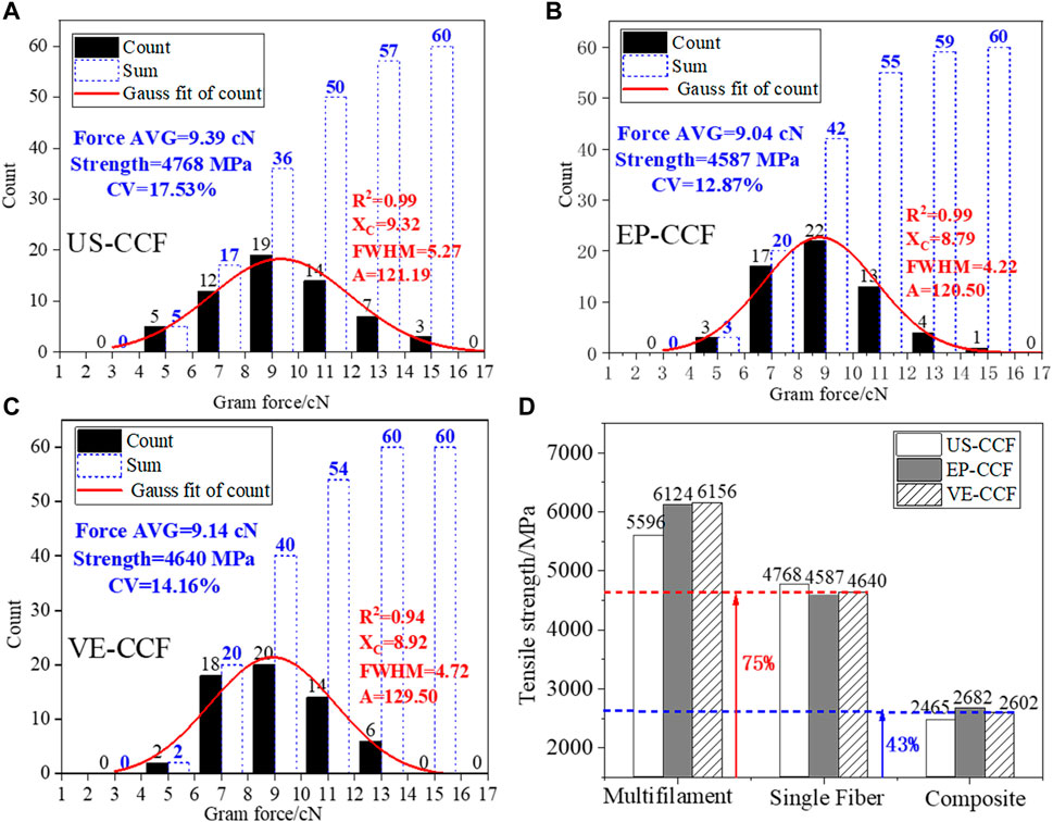
Figure 7. (A–C) Carbon fiber sample filament strength distribution and fitting chart; (D) Comparison of the strength of carbon fiber samples in multifilament, single fibers, and their composite materials.
The results of interlaminar shear strength under various conditions are presented in Table 5. According to the GB/T method, the interlaminar shear strength of carbon fibers is approximately 108 MPa, 118 MPa, and 130 MPa, respectively. The interlaminar shear strength measured by ASTM methods in the three states is lower than that measured by the GB/T method, which is attributed to differences in testing standards, but the overall trend is consistent. The difference in sample preparation methods leads to significant variations in the two test results. The test specimens for the RTD-ASTM method are prepared by using an autoclave to fabricate carbon fiber composite plates, which are then cut into the required dimensions for testing using a carving machine. The RTD-GB/T method, on the other hand, involves manually wrapping carbon fibers onto the sample plate, applying resin, and then using a standard-sized mold to heat and press the material into the required dimensions for testing. It is speculated that the main reason for this is the poorer consistency of fibers and the tendency to produce fuzz fibers during the manual wrapping process of the RTD-GB/T method. These fuzz fibers form an interpenetrating network in three-dimensional space, which acts as reinforcement, resulting in higher interlaminar shear strength. Generally, under the premise of matching sizing agents with resins, increasing the proportion of active C atoms on the carbon fiber surface through sizing agents is beneficial for enhancing interlaminar shear performance. Comparing the interlaminar shear strength at room temperature, 80°C, and 120°C, the interlaminar shear performance of composite materials linearly decreases with increasing processing temperature. At 120°C, the interlaminar shear strength of samples US-CCF, EP-CCF, and VE-CCF is only 41.0%, 42.8%, and 47.2% of that at room temperature, respectively. With the increase in the proportion of active C atoms on the carbon fiber surface, the interlaminar shear performance improves under all conditions. Overall, the sizing agent VE demonstrates a more significant improvement in interlaminar shear performance compared to the EP sizing agent. The addition of ethylene ester epoxy components increases the proportion of active C atoms on the carbon fiber surface, thereby enhancing the interfacial bonding performance of the composite material.
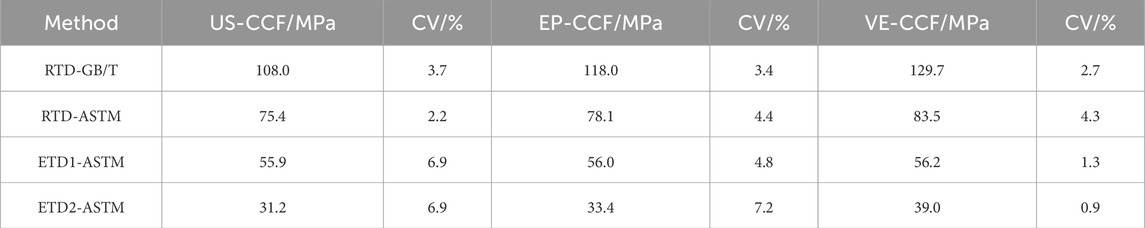
Table 4. Interlaminar shear strength results under various conditions.
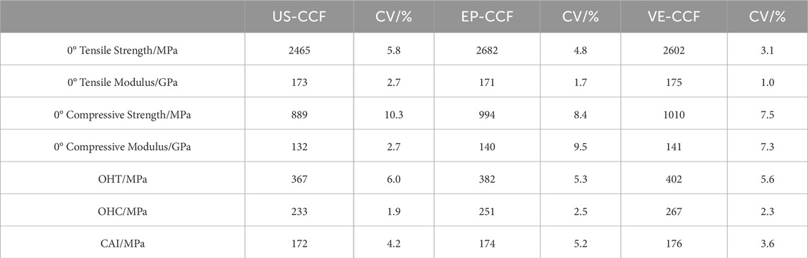
Table 5. Test results of carbon fiber composite material properties.
From Figures 8, 9, it is observed that under the condition of sizing agent matching on carbon fibers, the interface has no significant impact on the 0° tensile performance of carbon fiber composite materials; however, a clear influence is observed on the open-hole tensile strength. The trend of open-hole tensile strength aligns with that of interlaminar shear strength. This alignment is due to the fact that after the formation of open-hole defects in the composite, the fibers exist in a discontinuous state. Initially, the load transmission is primarily fiber-dominated, but as it transitions from a non-open-hole to an open-hole state, it shifts to a state jointly dominated by both the fibers and the interface. In this state, the interface plays a crucial role in load transmission.
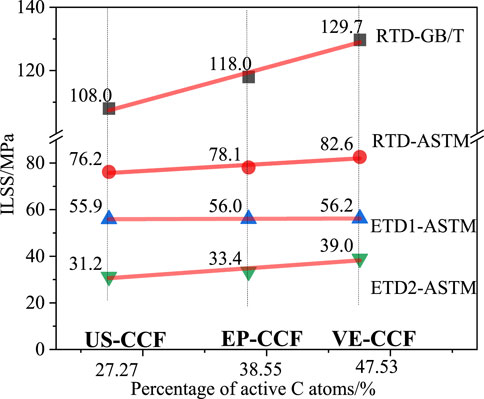
Figure 8. Relationship between the proportion of surface-active carbon atoms in carbon fiber and interlaminar shear strength.
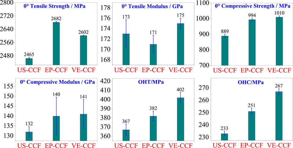
Figure 9. Main performance data of carbon fiber composite materials.
Further investigation through Figure 10 reveals the relationship between compression performance and interlaminar shear strength. It is found that the 0° compression strength and open-hole compression strength of untreated US-CCF are notably low. The 0° compression strength and open-hole compression strength of EP-CCF and VE-CCF are respectively higher than those of US-CCF by 11.8% and 13.6%, and 7.7% and 14.6%. The difference between EP-CCF and VE-CCF samples is small, indicating that the influence of the type of sizing agent on the 0° compression strength and open-hole compression strength is relatively minor compared to the presence or absence of sizing agents. Considering the difference between EP-CCF and VE-CCF, it is observed that the sizing agent used for VE-CCF contains additional components of vinyl ester epoxy resin compared to that used for EP-CCF. This results in a significant increase in the quantity of active carbon atoms on the carbon fiber surface. Overall, the performance of composite materials with VE-CCF samples is either superior to or comparable to that of EP-CCF samples, indicating that the addition of vinyl ester epoxy resin sizing agent components contributes to improving the interface performance of sizing agents determined by carbon fiber and ultimately enhances the performance of composite materials. Although there is an improvement in compression after impact, it remains at the same level, suggesting that the impact of improving the composite material interface brought by the sizing agent on the compression after impact of the composite material is limited, or even negligible.
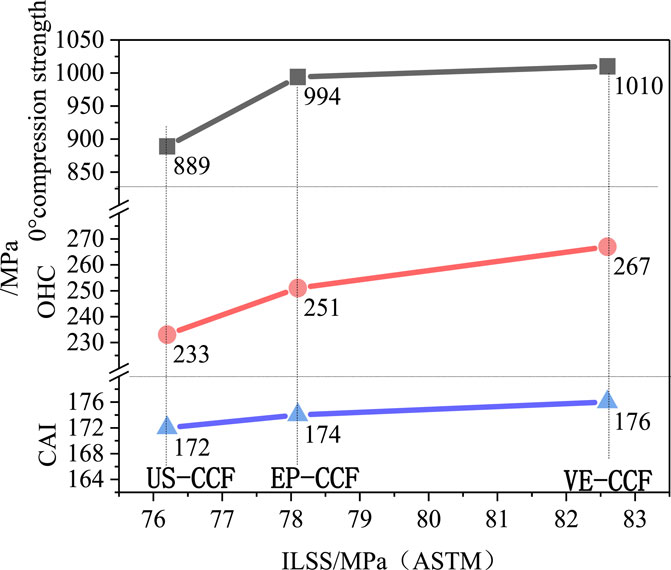
Figure 10. Relationship between ILSS and various compression strengths.
In summary, it is observed that regulating the sizing agent to enhance the quantity of active functional groups and the proportion of active carbon atoms on the surface of carbon fibers significantly improves the interlaminar shear performance of carbon fibers. Under the premise of matching the sizing agent with the matrix resin, this improvement in interface bonding performance positively enhances the open-hole compression performance, but has an insignificant effect on increasing the 0° compression strength of carbon fiber composites. Additionally, there is no apparent relationship between interface performance and improving compression strength after impact. Compared to differences in sizing agents, the presence or absence of sizing agents has a greater impact on the compression performance of carbon fibers.
Through high-magnification scanning electron microscope, observations were made on composite compression failure samples from three dimensions: fiber-resin delamination state, fracture surface state, and post-failure fiber distribution state, as shown in Figures 11, 12. From the perspective of fiber-resin delamination state, it is evident that the fiber pits left after delamination of US-CCF are clear and relatively smooth, with few tooth-like marks left by interface detachment, indicating poor interface bonding between carbon fibers and resin due to the limited active functional groups on the carbon fiber surface in the absence of sizing agent layers. In contrast, EP-CCF and VE-CCF show clear resin tear marks left by strong interface separation. From the fracture surface images, it is observed that the interface bonding state between fibers and resin is excellent in samples with sizing agents, while in the case of US-CCF without sizing agents, gaps between fibers and resin are visible, along with holes where fibers are completely pulled out and interlayer splitting, indicating a poorer interface bonding state between fibers and resin.
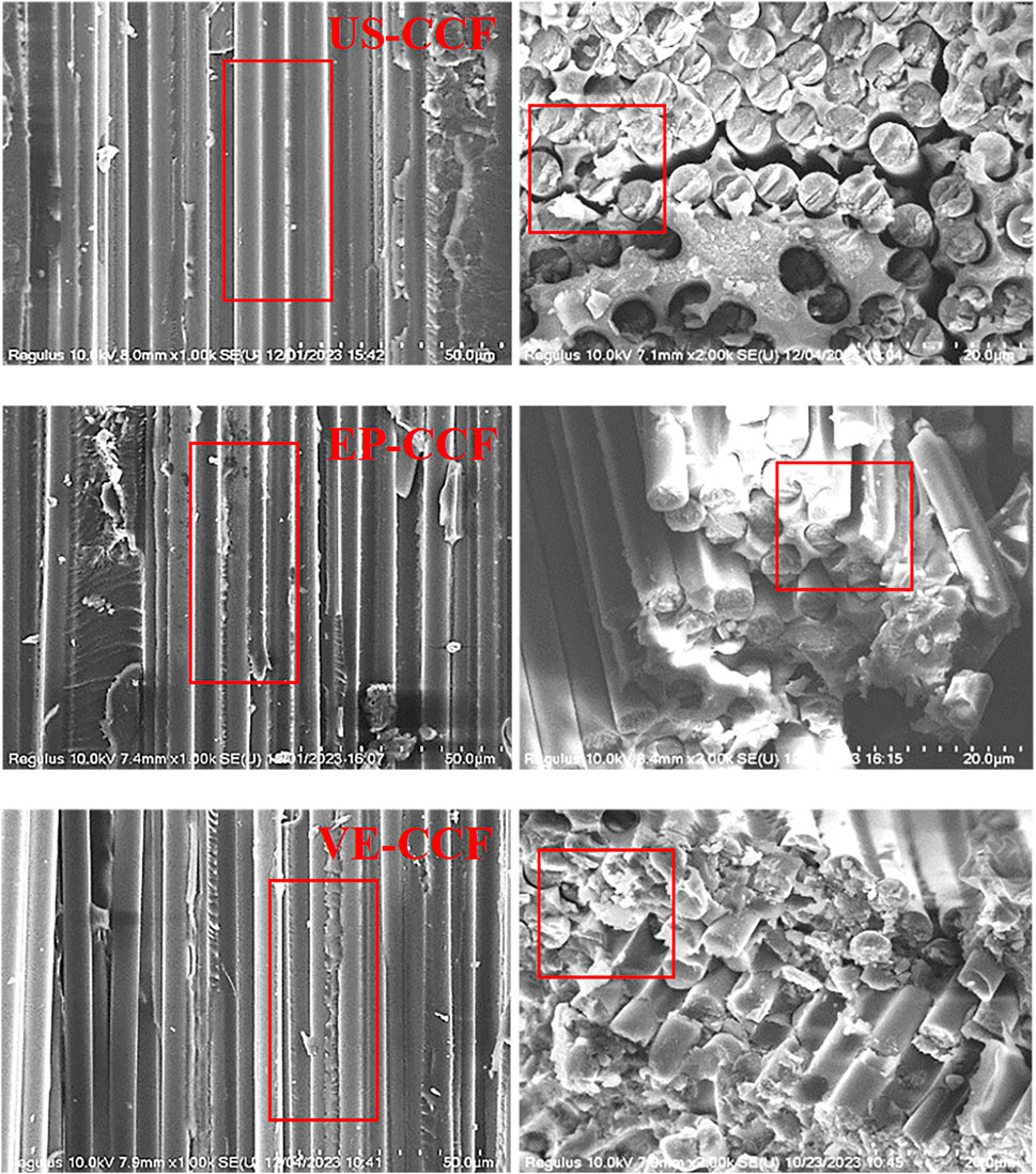
Figure 11. High-resolution SEM images of composite material compression section.
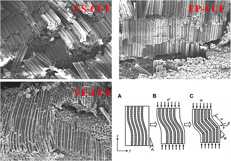
Figure 12. SEM images of composite material compression failure and schematic of kinked-band (Talreja and Waas, 2022) Fracture. SEM images of composite material compression failure and schematic of kinked-band (Li and Xian, 2019a) fracture.
Further observation of the fiber fracture morphology in the compression-failed samples revealed that the fracture morphology of the US-CCF sample exhibited interlayer failure triggering fiber fracture, with clear longitudinal delamination and significant fiber fragmentation after bending. The EP-CCF sample also exhibited fiber fragmentation after bending, but with less apparent delamination. In the case of VE-CCF, fibers exhibited a Kinked-Band formation due to resin bending-induced fiber buckling after shear stress concentration (Rosen, 1965; Sun and Chen, 1989; Sun and June, 1994). It also further demonstrates that the excellent interface performance formed by matching sizing agents is a prerequisite for the formation of kinked-Band failure during compression. The superior interface performance can prevent shear failure, interlayer failure, or interface failure in composite materials when subjected to compressive loading. Through research, it has been found that good interfacial bonding is a prerequisite for carbon fiber composites to maintain their compression performance. Only when the interface is well bonded, can the good interfacial bonding prevent debonding or slippage between fibers and resins when the composite material is subjected to compressive loads. This prevents interfacial delamination that would lead to compression instability and failure. For unsized US-CCF, its compression strength is relatively low, and obvious interfacial delamination can be observed in the SEM images of compression failure. However, after sizing with VE-CCF and other sizing agents, the interfacial properties are improved and enhanced. When carbon fiber composites are subjected to compressive loads, they do not fail due to interfacial delamination first. Instead, under the premise of good interfacial performance, the fibers undergo microbuckling, and the compression failure of the composite material is caused by the resin destruction in the form of kinked band failure.
Sizing agents have a significant effect on regulating the surface properties of carbon fibers. The sizing agents EP and VE can increase the O atom content on the carbon fiber surface by 13.0% and 18.1% respectively, and the active C atom ratio by 11.3% and 20.3%. VE achieves more excellent surface properties compared with EP. After sizing, the interlaminar shear strength (GB/T) of EP-CCF and VE-CCF increased by 9.3% and 20.0% compared with US-CCF, respectively, indicating that the chemical bonding of active functional groups has a significant effect on improving the interlaminar shear strength. The sizing agent itself does not contribute to the tensile strength, but it affects the tensile strength of carbon fibers and their composites by determining the consistency and collective force of the tow. Under the premise of matching the sizing agent with the matrix resin, the open-hole tensile and compressive properties are positively improved by improving the interfacial bonding performance. Specifically, the open-hole tensile strength and open-hole compressive strength of EP-CCF and VE-CCF increased by 4.1% and 9.5%, 7.7% and 14.6% compared with US-CCF, respectively. However, the effect on improving the 0° compressive strength and post-impact compressive strength of carbon fiber composites is not significant. Compared with the difference in the type of sizing agent, the presence or absence of the sizing agent has a greater impact on the compression performance of carbon fibers and their composites.
The raw data supporting the conclusion of this article will be made available by the authors, without undue reservation.
XO: Writing–original draft, Writing–review and editing. GG: Writing–original draft. YG: Writing–review and editing. YZ: Writing–review and editing. TP: Writing–original draft. XW: Writing–original draft. WZ: Writing–review and editing. YB: Writing–review and editing. YL: Writing–review and editing. SD: Writing–review and editing. KN: Writing–original draft, Writing–review and editing, Methodology, Resources, Supervision.
The author(s) declare that financial support was received for the research, authorship, and/or publication of this article. The research in this paper was financially supported by Zhongfu Shenying Carbon Fiber Co., Ltd., but this support is between the enterprise and the school, and the grant number and funding information that can be accessed online are not available, so it cannot be reflected. After communication, it is confirmed that it will not be reflected in the article.
Thank you to the Jiangsu Industrial Technology Research Institute for your support in this research.
Authors GG, TP, XW, and WZ were employed by Zhongfu Shenying Carbon Fiber Company Limited. This study was financially supported by Zhongfu Shenying Carbon Fiber Co., Ltd., and the experimental site was provided by Zhongfu Shenyin Carbon Fiber Co., Ltd. Additionally, co-authors GG, TP, XW, and WZ from Zhongfu Shenyin Carbon Fiber Co., Ltd. participated in assisting with the experiments and collecting data.
The remaining authors declare that the research was conducted in the absence of any commercial or financial relationships that could be construed as a potential conflict of interest.
All claims expressed in this article are solely those of the authors and do not necessarily represent those of their affiliated organizations, or those of the publisher, the editors and the reviewers. Any product that may be evaluated in this article, or claim that may be made by its manufacturer, is not guaranteed or endorsed by the publisher.
Biswas, P. K., Omole, O., Peterson, G., Cumbo, E., Agarwal, M., and Dalir, H. (2023). Carbon and cellulose based nanofillers reinforcement to strengthen carbon fiber-epoxy composites: processing, characterizations, and applications. Front. Mater. 9, 1089996. doi:10.3389/fmats.2022.1089996
Chen, J., Liu, J. Y., and Wang, D. Z. (2011). Effect of emulsion type sizing agents on the properties of carbon fiber and carbon fiber reinforced polymer matrix composite. Adv. Mater. Res. 236-238, 2295–2298. doi:10.4028/www.scientific.net/amr.236-238.2295
Deng, C., Jiang, J., Liu, F., Fang, L., Wang, J., Li, D., et al. (2015). Influence of carbon nanotubes coatings onto carbon fiber by oxidative treatments combined with electrophoretic deposition on interfacial properties of carbon fiber composite. Appl. Surf. Sci. 357, 1274–1280. doi:10.1016/j.apsusc.2015.09.178
Deng, C., Jiang, J., Liu, F., Fang, L., Wang, J., Li, D., et al. (2016). Influence of surface properties of graphene oxide/carbon fiber hybrid fiber by oxidative treatments combined with electrophoretic deposition. Surf. Interface Analysis 48 (4), 212–217. doi:10.1002/sia.5944
Fu, S. Y., Feng, X. Q., Lauke, B., and Mai, Y. W. (2008). Effects of particle size, particle/matrix interface adhesion and particle loading on mechanical properties of particulate–polymer composites. Compos. Part B Eng. 39 (6), 933–961. doi:10.1016/j.compositesb.2008.01.002
Gao, B., Zhang, R. L., He, M. S., Sun, L., Wang, C., Liu, L., et al. (2016). Effect of a multiscale reinforcement by carbon fiber surface treatment with graphene oxide/carbon nanotubes on the mechanical properties of reinforced carbon/carbon composites. Appl. Sci. Manuf. 90, 433–440. doi:10.1016/j.compositesa.2016.08.012
Geng, Y. Z., Li, H. F., Yao, J. W., Niu, K., Naik, M. u. d., Ahmad, M., et al. (2023). Novel preparation of nano-SiO2 core-shell hybrid inorganic-organic sizing agents for enhanced interfacial and mechanical properties of carbon fibers/epoxy composites. Compos. Struct. 319, 117086. doi:10.1016/j.compstruct.2023.117086
Guang, Y., Huazhen, W., Dayong, L., Shouzhen, G., Changyong, L., Kaibao, M., et al. (2019). Research progress of carbon fiber sizing agent and its effects on interface properties of composites. Eng. Plast. Appl. 47 (2), 143–147. doi:10.3969/j.issn.1001-3539.2019.02.026
Guo, J., Lu, C., and An, F. (2012). Effect of electrophoretically deposited carbon nanotubes on the interface of carbon fiber reinforced epoxy composite. J. Mater. Sci. 47 (6), 2831–2836. doi:10.1007/s10853-011-6112-5
Hao, W., Chun, Y., Hai-Bing, X., Chao, L., Gang, C., Dong, L., et al. (2016). Research progress of carbon fiber sizing agent. Thermosetting Resin, 65–69.
Jia, Li. (2020). Analysis of compression behavior of carbon fibers and its composites. Master's thesis. Beijing: Beijing University of Chemical Technology.
Jiang, J. J., Liu, F., Deng, C., Fang, L. C., and Li, D. J. (2015). Influence of deposited CNTs on the surface of carbon fiber by ultrasonically assisted electrophoretic deposition. IOP Conf. Ser. Mater. Sci. Eng. 87, 012103. doi:10.1088/1757-899x/87/1/012103
Li, C., and Xian, G. (2019a). Experimental investigation of the microstructures and tensile properties of polyacrylonitrile-based carbon fibers exposed to elevated temperatures in air. J. Eng. Fibers Fabr. 14, 155892501985001. doi:10.1177/1558925019850010
Li, C., and Xian, G. (2019b). Experimental and modeling study of the evolution of mechanical properties of pan-based carbon fibers at elevated temperatures. Materials 12 (5), 724. doi:10.3390/ma12050724
Li, C., Xian, G., and Li, H. (2019). Effect of postcuring immersed in water under hydraulic pressure on fatigue performance of large-diameter pultruded carbon/glass hybrid rod. Fatigue & Fract. Eng. Mater. Struct. 42 (5), 1148–1160. doi:10.1111/ffe.12978
Li, M., Zhu, S., Ouyang, Q., Ma, H., Xu, J., Chen, Y., et al. (2018). Relationship between the structure of domestic high strength intermediate modulus carbon fibers with different diameter and their axial compressive strength. High-tech Fiber Appl. 6, 33–39. doi:10.3969/j.issn.1007-9815.2018.06.004
Liu, J. (2012). Preparation and performance of vinyl ester resin emulsion type sizing agent for carbon fiber. Master's thesis. Guangzhou: Jinan University.
Lu Gan (2020). The correlation between fiber structure and longitudinal compressive properties of carbon fibers. Master's thesis. Beijing: Beijing University of Chemical Technology.
Marouf, B. T. (2009). Effect of microstructure factors on fracture behavior of clay-rubber-epoxy hybrid nanocomposites. Ph.D. dissertation. Tehran: Sharif University of Technology.
Marouf, B. T., Mai, Y. W., Bagheri, R., and Lauke, B. (2016). Toughening of epoxy nanocomposites: nano and hybrid effects. Polym. Rev. 56 (1), 70–112. doi:10.1080/15583724.2015.1086368
Marouf, B. T., Pearson, R. A., and Bagheri, R. (2009). Anomalous fracture behavior in an epoxy-based hybrid composite. Mater. Sci. Eng. A 515 (1-2), 49–58. doi:10.1016/j.msea.2009.03.028
Nunna, S., Ravindran, A. R., Mroszczok, J., Creighton, C., and Varley, R. J. (2023). A review of the structural factors which control compression in carbon fibres and their composites. Compos. Struct. 303, 116293. doi:10.1016/j.compstruct.2022.116293
Ouyang, X., Liu, F., Huang, X., Qi, L., and Sun, W. (2016). Influence of the type and content of sizing agent on the carbon fibers surface properties. Fiber Reinf. Plastics/Composites Mater., 5, 68–73. doi:10.3969/j.issn.1003-0999.2016.05.012
Prabhakar, P., and Waas, A. M. (2013). Interaction between kinking and splitting in the compressive failure of unidirectional fiber reinforced laminated composites. Compos. Struct. 98, 85–92. doi:10.1016/j.compstruct.2012.11.005
Qi, B., Zhang, Q. X., Bannister, M., and Mai, Y. W. (2006). Investigation of the mechanical properties of DGEBA-based epoxy resin with nanoclay additives. Compos. Struct. 75 (1-4), 514–519. doi:10.1016/j.compstruct.2006.04.032
Rosen, B. W. (1965). Mechanics of composite strengthening in fiber composite materials. Am. Soc. Metals, 37–75.
Shi, P., Shang, C., Chen, L., Zhao, H., Zhou, Y., Zhu, S., et al. (2021). Compressive strength of carbon fiber reinforced epoxy composites with various carbon fiber cross section characteristics. Acta Mater. Compos. Sin. 38 (12), 4052–4059. doi:10.13801/j.cnki.fhclxb.20210203.001
Subramaniyan, A. K., and Sun, C. T. (2006). Enhancing compressive strength of unidirectional polymeric composites using nanoclay. Compos. Part A Appl. Sci. Manuf. 37 (12), 2257–2268. doi:10.1016/j.compositesa.2005.12.027
Sun, C. T., and Chen, J. L. (1989). A simple flow rule for characterizing nonlinear behavior of fiber composites. J. Compos. Mater. 23 (10), 1009–1020. doi:10.1177/002199838902301004
Sun, C. T., and Jun, A. W. (1994). Compressive strength of unidirectional fiber composites with matrix non-linearity. Compos. Sci. Technol. 52 (4), 577–587. doi:10.1016/0266-3538(94)90041-8
Talreja, R., and Waas, A. M. (2022). Concepts and definitions related to mechanical behavior of fiber reinforced composite materials. Compos. Sci. Technol. 217, 109081. doi:10.1016/j.compscitech.2021.109081
Toray Industries (2023). Toray Industries, Inc. Available at: http://www.Toraycma.Com/page.Php?Id=661 (Accessed September 19, 2023).
Totry, E., Molina-Aldareguia, J. M., Gonzalez, C., and Llorca, J. (2010). Effect of fiber, matrix and interface properties on the in-plane shear deformation of carbon-fiber reinforced composites. Compos. Sci. Technol. 70 (6), 970–980. doi:10.1016/j.compscitech.2010.02.014
Wang, X. Q., Liu, Z. B., Liu, H. S., Zhao, Y., and Guan, Z. D. (2022). Effect of sizing agent on interface properties of domestic T800 grade carbon fiber reinforced thermosetting composite. Acta Mater. Compos. Sin. 39 (09), 4393–4405. doi:10.13801/j.cnki.fhclxb.20220104.001
Wang, Z. (2021). Characterization of intrinsic compression strength of carbon fiber by bundle method and research on its correlation with structure. Master's thesis. Beijing: Beijing University of Chemical Technology.
Wang, Z., Huang, X., Xian, G., and Li, H. (2016). Effects of surface treatment of carbon fiber: tensile property, surface characteristics, and bonding to epoxy. Polym. Compos. 37 (10), 2921–2932. doi:10.1002/pc.23489
Wenmo, Z. (2019). Prediction of compression strength of carbon fiber composites and study on its influencing factors. Master's thesis. Beijing: Beijing University of Chemical Technology.
Wu, B. (2017). Research on surface modification of polyacrylonitrile carbon fiber and properties of composite materials. Doctor's thesis. Tianjin, China: Tianjin Polytechnic University.
Wu, Z. J., Cui, H. Y., Chen, L., Jiang, D., Weng, L., Ma, Y., et al. (2018). Interfacially reinforced unsaturated polyester carbon fiber composites with a vinyl ester-carbon nanotubes sizing agent. Compos. Sci. Technol. 164, 195–203. doi:10.1016/j.compscitech.2018.05.051
Xinfeng, O., Fen, W., Yuting, S., Zhenzhen, T., and Fang, L. (2018). Comprehensive performance characterization of main carbon fiber varieties at home and abroad. High-tech Fiber Appl. 43 (05), 48–57. doi:10.3969/j.issn.1007-9815.2018.05.007
Xingyao, S., Meng, L., Yaofeng, Z., and Yaqin, F. (2016). Effect of waterborne sizing agent on carbon fiber surface and properties of carbon fiber/epoxy composites interface. Acta Mater. Compos. Sin. 33 (02), 273–279. doi:10.13801/j.cnki.fhclxb.20150616.002
Xiong, S., Zhao, Y., and Liu, Z. (2023). Effect of plasma treatment on the interfacial properties of domestic high-strength carbon fiber composite. New Chem. Mater. 51 (08), 114–118. doi:10.19817/j.cnki.issn1006-3536.2023.08.022
Young, R. J., Kinloch, I. A., Gong, L., and Novoselov, K. S. (2012). The mechanics of graphene nanocomposites: a review. Compos. Sci. Technol. 72 (12), 1459–1476. doi:10.1016/j.compscitech.2012.05.005
Yuan, X. M., Zhu, X., Cai, X., Liu, J., Qiao, K., and Yu, J. (2017). Improved interfacial adhesion in carbon fiber/epoxy composites through a waterborne epoxy resin sizing agent. J. Appl. Polym. Sci. 134 (17), 44757. doi:10.1002/app.44757
Zhang, C. H., Zhang, Z. Q., and Cao, H. L. (2007). Effects of epoxy/SiO2 hybrid sizing on the mechanical properties of carbon fiber composites. Solid State Phenom. 121, 1253–1256. doi:10.4028/www.scientific.net/ssp121-123.1253
Zhang, M. (2010). Study on the key factors of interface bonding strength of carbon fiber reinforced resin composite. Doctor's thesis. Jinan, China: Shandong University.
Zhang, R. L., Liu, Y., Huang, Y. D., and Liu, L. (2013). Effect of particle size and distribution of the sizing agent on the carbon fibers surface and interfacial shear strength (IFSS) of its composites. Appl. Surf. Sci. 287, 423–427. doi:10.1016/j.apsusc.2013.09.174
Zhang, X. P., Liu, L., Li, M., Chang, Y., Shang, L., Dong, J., et al. (2016). Improving the interfacial properties of carbon fibers/vinyl ester composites by vinyl functionalization on the carbon fiber surface. RSC Adv. 6 (35), 29428–29436. doi:10.1039/c6ra00829a
Zhao, X., Zhang, Q., Guo, J., Gao, L., Sui, G., and Yang, X. (2017). Effect of epoxide sizing treated MWCNTs of MWCNTs/epoxy composites. Acta Mater. Compos. Sin. 34 (2), 247–255. doi:10.13801/j.cnki.fhclxb.20160511.001
Zhao, Z. B. (2017). Mechanical, interfacial, and fatigue resistance properties of carbon fiber reinforced epoxy composites modified with carbon nanotubes. Master's thesis. Tianjin: Tianjin Polytechnic University.
Keywords: sizing agent, unsized carbon fiber, interface performance, carbon fiber composite materials, compression performance
Citation: Ouyang X, Ge G, Geng Y, Zong Y, Pan T, Wang X, Zhu W, Bai Y, Liu Y, Duan S and Niu K (2024) Research on the effect of sizing agent on the interface and compression performance of carbon fiber composites. Front. Mater. 11:1437104. doi: 10.3389/fmats.2024.1437104
Received: 23 May 2024; Accepted: 12 July 2024;
Published: 22 August 2024.
Edited by:
Xiangdong Liu, Changchun Institute of Applied Chemistry (CAS), ChinaCopyright © 2024 Ouyang, Ge, Geng, Zong, Pan, Wang, Zhu, Bai, Liu, Duan and Niu. This is an open-access article distributed under the terms of the Creative Commons Attribution License (CC BY). The use, distribution or reproduction in other forums is permitted, provided the original author(s) and the copyright owner(s) are credited and that the original publication in this journal is cited, in accordance with accepted academic practice. No use, distribution or reproduction is permitted which does not comply with these terms.
*Correspondence: Kangmin Niu, bml1a21AdXN0Yi5lZHUuY24=
Disclaimer: All claims expressed in this article are solely those of the authors and do not necessarily represent those of their affiliated organizations, or those of the publisher, the editors and the reviewers. Any product that may be evaluated in this article or claim that may be made by its manufacturer is not guaranteed or endorsed by the publisher.
Research integrity at Frontiers
Learn more about the work of our research integrity team to safeguard the quality of each article we publish.