 Imran Khan
 Asma Alshehri3
 Ibrahim A. Hameed
94% of researchers rate our articles as excellent or good
Learn more about the work of our research integrity team to safeguard the quality of each article we publish.
Find out more
ORIGINAL RESEARCH article
Front. Mater. , 31 July 2024
Sec. Metamaterials
Volume 11 - 2024 | https://doi.org/10.3389/fmats.2024.1428912
Introduction: The emergence of electromagnetic wave pollution as a new form of pollution in human society is attributed to the advancements in communication technology and the electronic information business. In addition to harming priceless electronic equipment, these electromagnetic radiation and interference issues brought on by electrical and electronic devices have a major negative influence on human productivity and wellbeing. The secret to getting rid of electromagnetic radiation interference (EMI) and improving performance is electromagnetic shielding technology. Metamaterial absorber is a type of metamaterial that absorb EMI radiation. The benefits of metamaterial absorbers include their lightweight, simple construction, and excellent absorptivity.
Methods: This paper proposes a novel metamaterial absorber for EMI radiation absorption. It consists of dielectric layers, metamaterial shielding layer and transmission line. The reflection of radiation is reduced by miniaturization of metamaterials.
Results and Discussion: Simulation results show that the proposed design has better performance as compared to existing methods. The operating frequency range is from 23.1 to 28.3 GHz. The values of S21 with and without shielding are −5 dB and −0.05 dB, and the shielding effectiveness is 10.10 dB and a maximum of 12.63 dB.
With the development of mobile communication technology, electronic systems continue to move towards miniaturization, high integration and high speed. In this process, flexible electronic technology has received widespread attention due to its excellent flexibility and has promoted wearable electronics (Shallah et al., 2024). The realization and rapid development of flexible electronic devices such as foldables and foldable electronic devices have been widely used in education, medical and industrial fields. However, as the signal frequency and the integration of electronic components increase, the intensity of electromagnetic interference (EMI) between components increases, and the electromagnetic environment on the printed circuit board (PCB) becomes more complex. If the electromagnetic radiation reaches a certain limit, it may even cause the entire circuit to collapse (Fu et al., 2023). The main device for signal transmission between PCBs or PCB on-board devices is the transmission line. Unlike when transmitting low-frequency signals, when the transmission line transmits high-frequency signals, the intensity of electromagnetic radiation generated in the space is greater, and the impact on other components is also worse (Lei et al., 2022). In traditional rigid PCBs, vias and metal films are usually used on transmission lines to form shielding cavities to suppress electromagnetic radiation and achieve good shielding performance. However, in flexible PCB, this solution will affect the flexibility of the transmission line, and is prone to produce parasitic capacitance and inductance, etc., causing signal integrity problems (Albawri et al., 2020; Norouzi et al., 2023). Thus, it is imperative to provide a method for suppressing electromagnetic radiation for flexible high-frequency transmission lines (Gupta et al., 2020).
The phenomenon of electromagnetic interference in transmission lines becomes more and more serious as the frequency increases. In recent years, domestic and foreign scholars have conducted a lot of research to solve this problem (Chien et al., 2020; Xie et al., 2022). The authors in (Suarez et al., 2020) proposed using ferrite materials to solve the problem of PCB board-level electromagnetic interference (EMI), that is, using the characteristics of ferrite materials to effectively absorb electromagnetic waves to reduce the interference caused by transmission lines in PCBs, and the electromagnetic radiation in the MHz frequency class. The authors in (Liu et al., 2023) proposed using magnetic electroplating alloys instead of ferrite materials to suppress electromagnetic radiation in PCBs, and conducted a test on shielding effectiveness with 4F1 ferrite materials at 500 kHz and 3 MHz frequencies. In comparison, similar shielding effectiveness is achieved with a thinner thickness. The authors in (Zhuang and Lin, 2023) studied the impact of the spacing and position of PCB edge vias on the electromagnetic radiation shielding effectiveness, and verified it in the range of 0–3 GHz. In rigid PCBs, vias are still widely used as the main space radiation suppression technology. However, as the frequency increases, due to the influence of parasitic parameters and impedance discontinuities, vias will inevitably cause signal transmission problems in the PCB. Causes signal integrity issues. Moreover, this problem is also inevitable in flexible PCB. The authors of (Wang et al., 2021) proposed a technique for shielding radiation from transmission lines and other PCB components by employing materials with high dielectric constants rather than vias. They tested it in the range of 0–10 GHz and found that with the frequency The shielding efficiency of high dielectric constant materials is better than that of via holes, but these materials are thicker and less flexible, so they are not suitable for flexible PCBs. Therefore, there are certain limitations in using the above technologies for electromagnetic radiation suppression in ultra-thin flexible high-frequency transmission lines, and most of them are reflective shielding solutions. In high-frequency application scenarios, reflected waves will affect the transmission performance of the transmission line. The use of low-reflective shielding technology can solve this problem.
Low-reflective shielding materials can effectively absorb electromagnetic radiation and improve electromagnetic compatibility near disturbed equipment. Early research on low-reflective materials mainly focused on ferrite and magnetic metal materials. Ferrite materials have the characteristics of strong absorption loss and low cost, but have low absorption frequency and high density. The authors in (Perdigones and Quero, 2022) proposed a ferrite material composed of CoFe2O4, with an absorption frequency band of 8.2–10.2 GHz, a thickness of 2 mm, and performance at 9.25 GHz with maximum reflection loss of −55 dB. Compared with ferrite materials, magnetic metal materials have stronger magnetism and greater absorption loss, but they have the disadvantages of high density and narrow absorption bandwidth. Reference (Tian et al., 2023) proposed a magnetic metal material composed of Ho-Ce-Co alloy with an effective absorption bandwidth of 1.6 GHz and a thickness of 2 mm, which can reach −42.99 dB at 6.48 GHz with maximum reflection loss. New low-reflection shielding materials are carbon-based, conductive polymer-based and metal sulfide-based materials. Carbon-based materials have the advantages of low density, large dielectric loss and adjustable conductivity, but they have the disadvantage of narrow absorption bandwidth. Reference (Chen et al., 2018) proposed a carbon-based material composed of graphene microflowers, which can absorb electromagnetic waves at 6.0–8.9 GHz. The thickness is 4 mm and can reach a maximum of −42.9 dB at 6.9 GHz. Conductive polymer-based materials have the advantages of large dielectric loss and strong conductivity, but they also have the disadvantage of narrow absorption bandwidth. Reference (Wang et al., 2018) proposed a conductive polymer-based shielding material composed of Ni/SiO2/polyaniline. The operating frequency range is 16.0–17.9 GHz and the thickness is 8.7 mm. It can reach 17.1 GHz with reflection loss of −41.5 dB. Metal sulfide-based materials have large dielectric losses and good electrical conductivity, but they also have the problem of large thickness. Reference (Wu et al., 2020) proposed a metal sulfide-based material composed of Fe3O4/Fe3S4, with an absorption frequency band of 5.8–8.4 GHz, a thickness of 3.3 mm, and a −45.3 dB at 7.1 GHz. The above low-reflection shielding materials used in high-frequency transmission lines have problems such as large thickness and narrow absorption bandwidth. Disadvantages: It is difficult to adapt to flexible transmission lines. The emergence of metamaterials has given new ideas to solve this problem.
Metamaterial is an artificially designed periodic sub-wavelength structure that has extraordinary physical properties that natural materials do not have, such as negative dielectric constant, negative magnetic permeability and negative refractive index, and has good control and absorption capabilities for electromagnetic waves. It has high application potential in electromagnetic stealth (Gao et al., 2023) and anti-jamming communications (Yang et al., 2020). Metamaterials are ultra-thin, and the thickness can be reduced to a few tenths of the operating wavelength. Due to its periodic array structure, the scale can be flexibly adjusted for application in various scenarios, and it can adapt to the trend of miniaturization of electronic systems (Ali and Alhindawi, 2021; Dai et al., 2023). The authors in (Hossain et al., 2023) proposed the concept of a perfect metamaterial absorber. They used hard FR4 material as the dielectric substrate and designed metal strip resonant structures on both sides to achieve electromagnetic wave amplitude control at 11.5 GHz. Reference (Araujo et al., 2020) proposed a flexible metamaterial structure, using PET material as the dielectric substrate to achieve good flexibility, and coating one side of it with a layer of conductive material with a square resistance of 74 Ω. The film is printed with a pattern, achieving effective absorption of electromagnetic waves in a wide frequency band of 4.1–19.3 GHz, that is, adjusting the amplitude. The authors in (Chung et al., 2022) deploys the Pancharatnam-Berry phase theory and introduced the propagation phase to design a metasurface that can achieve complete phase control when circularly polarized incident, and in the range of 9–11 GHz. The authors in (Wu et al., 2022) proposed a metamaterial design method with full control of amplitude, phase and polarization. By introducing the concept of “metamaterial atoms” constituting “metamaterial molecules”, they realized the control of electromagnetic wave amplitude, control of phase and other parameters. Due to the significant advantages of metamaterials in volume, form and function compared to traditional materials in regulating the amplitude, phase and polarization of electromagnetic waves, they are not only widely used in perfect lenses, electromagnetic stealth and other scenarios, but their miniaturization characteristics make them at high research value in improving the electromagnetic compatibility of micro-devices such as mobile terminals.
In response to the aforementioned problems, this paper proposes a low-reflection scheme that uses miniaturized metamaterial structures to shield electromagnetic radiation for high-frequency flexible transmission lines.
The main contributions are as follows.
1) By coupling the transmission line to the metamaterial structure, the metamaterial’s regulation and absorption characteristics of electromagnetic waves are used to suppress electromagnetic radiation, and the equivalent parameter theory and equivalent circuit theory are used to analyze and verify the designed miniaturized metamaterial structure.
2) A segmented transmission line with coplanar characteristics is designed for simulation and testing that operates in the FR2 frequency of 5G.
3) By comparing the S-parameters and electromagnetic radiation intensity of the segmented coplanar waveguide transmission line before and after adding the metamaterial shielding structure, the performance of the metamaterial in maintaining transmission quality and suppressing electromagnetic radiation of the transmission line was verified, and the actual product was processed for testing.
Metamaterials are composed of artificially designed periodic subwavelength structural units, with carefully designed structural patterns on a single structure. When the radiated electromagnetic wave is incident on the surface pattern, if it matches the working frequency band of the metamaterial structure, a strong electromagnetic resonance will be generated. Therefore, the metamaterial has good control and absorption capabilities for electromagnetic waves. By coupling it with a high-frequency flexible transmission line, it can be used in regulate and absorb radiated electromagnetic waves within a wide frequency band to achieve electromagnetic shielding.
The suppression of electromagnetic radiation from transmission lines by metamaterial structures, that is, the regulation of electromagnetic waves, can be analyzed from multiple angles. Specifically, it mainly includes the control of three aspects: amplitude, phase and polarization.
First, the metamaterial structure regulates the amplitude of electromagnetic waves mainly through electromagnetic loss, which is mainly divided into two parts: dielectric loss and ohmic loss. The dielectric substrate of the metamaterial structure is usually a lossy material. When electromagnetic waves are incident into the medium, if magnetic resonance occurs, the surface pattern and the metal backing plate will generate anti-parallel currents, and a certain displacement current will be generated in the medium. This part is called dielectric loss (Holloway et al., 2012; Ding et al., 2016; Li Y. et al., 2023). Ohmic loss is mainly caused by the incident electromagnetic wave exciting the resonance of the metal structure on the surface of the metamaterial. Since the metamaterial can electrically resonate with the electromagnetic wave at a certain frequency point or within a certain frequency band, this part of the electromagnetic wave will be converted into current and lost. When the high-frequency electromagnetic wave radiated by the transmission line is incident on the surface of the metamaterial structure, if it matches the working frequency band of the metamaterial, it will enter the interior of the structure and be partially transmitted. Define the transmittance
Second, metamaterials can effectively control the phase of electromagnetic waves in the microwave band. For a reflective metamaterial structure with a complete metal backplate on one side of the medium, assuming that the dielectric constants before and after the electromagnetic wave is incident (the metamaterial dielectric layer) are
In the formula:
On this basis, the reflection phase of the metamaterial structure can be expressed in Eq. 3
In the formula:
Third, the control of the polarization of incident electromagnetic waves is also an important part of the structural properties of metamaterials. Generally speaking, the polarization of electromagnetic waves can be divided into three categories: linear polarization, circular polarization and elliptical polarization (Sun et al., 2021; Dai et al., 2022). Metamaterials can effectively convert the polarization of electromagnetic waves by changing characteristics such as amplitude and phase through specific design.
Therefore, compared with the traditional reflective shielding structure, the metamaterial structure reduces the reflection component and changes the characteristics of the reflected wave when suppressing the high-frequency radiation of the transmission line, which can effectively maintain the transmission performance of the transmission line.
To comply with the trend of high integration of electronic systems, the designed metamaterial structure has the characteristics of miniaturization and uses flexible materials to ensure matching with flexible transmission lines. The front and three-dimensional views of the designed metamaterial structural unit are shown in Figures 1A,B respectively. The main structure consists of metamaterial patterns, dielectric substrates and metal back plates. The unit size is 0.079λ0 × 0.079λ0 (λ0 is the wavelength corresponding to the lowest cutoff frequency in the operating bandwidth), and the thickness is only 0.04λ0.
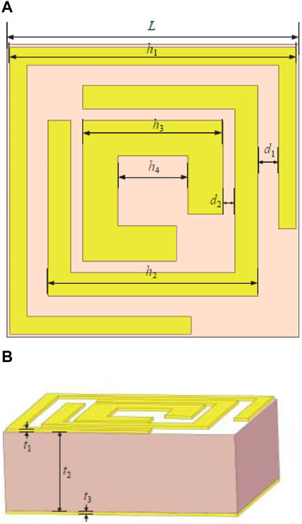
Figure 1. Proposed design. (A) Front view; (B) side view.
As can be seen from Figure 1A, the metamaterial pattern consists of three square open split rings of different sizes. The coupling between the three resonant rings is used to increase the resonance points (Cao et al., 2021; Xu G. et al., 2023; Zhang et al., 2023), and finally achieves electromagnetic wave response in a wide frequency band.
The metamaterial pattern and the metal backplane are both made of metallic copper, with a conductivity of 5.8 × 10⁷ S/m and a thickness t1 of 0.018 mm. The dielectric substrate is made of polyimide material, with a dielectric constant of 3.5, a loss tangent tan δ of 0.0027, and a thickness t2 of 0.48 mm. One side of the dielectric substrate is completely covered by a metal backplane, so the transmittance of electromagnetic waves is zero. The complete geometric parameters are shown in Table 1.
Table 1. Design parameters.
When conducting research on the electromagnetic properties of metamaterial structures, commercial simulation software CST was used for modeling. The boundary conditions in the x and y directions were set to the “unit cell” periodic boundary, and the z direction was set to an open boundary. A frequency domain solver was used for modeling electromagnetic parameters.
The comparison of the S-parameters of the metamaterial structure when TE and TM polarized electromagnetic waves are vertically incident is shown in Figure 2A. In the frequency range of 23.10–28.30 GHz, S11 is lower than −10 dB, showing that it is sensitive to electromagnetic waves having hood control and absorption performance, with the best reflection loss of −44 dB at 27.56 GHz. The reflection phases of the two polarized waves when they are vertically incident are shown in Figure 2B. Within the metamaterial operating frequency band (Yang M. et al., 2023), the phase undergoes multiple mutations, and incident waves of different frequencies show different reflection phases. On the other hand, for TE and TM polarization waves, the designed metamaterial structure shows consistent electromagnetic control performance, and therefore has polarization insensitivity.
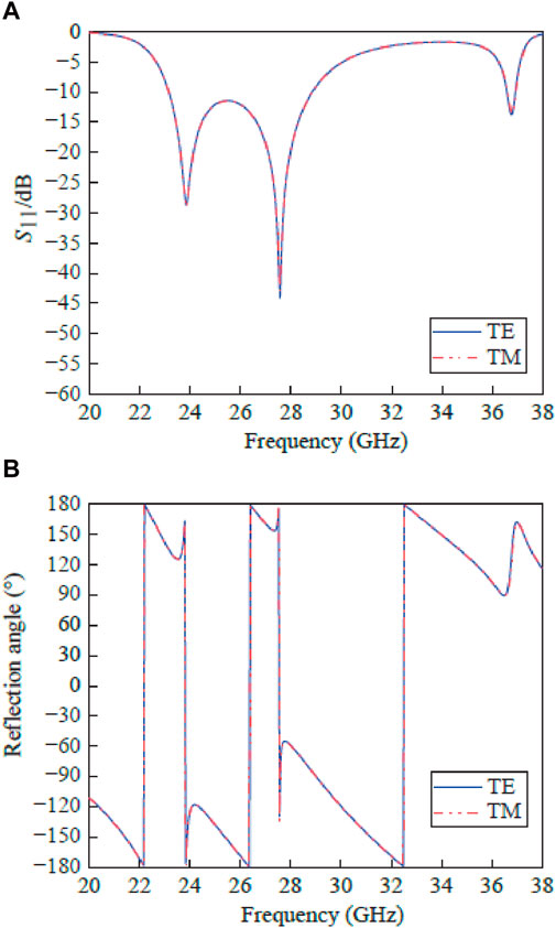
Figure 2. Vertical incident electromagnetic waves evaluation. (A) S-parameter; (B) reflection phase.
When conducting research on the regulation and absorption of electromagnetic waves in metamaterial structures, impedance matching is an important aspect. Impedance matching refers to the degree of reflection and absorption of electromagnetic waves by metamaterials when electromagnetic waves are incident on the surface of a metamaterial structure (Gao et al., 2024; Xu and Shin, 2024), so it is closely related to the performance of metamaterials. After the incident electromagnetic wave interacts with the metamaterial, it is divided into three parts, namely, reflected, transmitted and absorbed electromagnetic waves. When designing a metamaterial structure, a metal conductor is usually used as a backplane to ensure that the transmission coefficient is 0. In this case, reducing the reflection coefficient S11 can increase the absorption rate (Liu et al., 2022). The reflection coefficient is calculated by Eq. 4
In the formula:
It will be normalized and compared with the equivalent impedance of the metamaterial. Impedance matching can be achieved when
In the designed metamaterial structure, one side of the dielectric substrate is completely covered by the metal backplane, and the transmission coefficient S21 is 0. The S-parameters are extracted from the CST simulation software, and the equivalent impedance is calculated using the programming software. The results are shown in Figure 3. The real part of the equivalent impedance of this structure is close to 1 and the imaginary part is close to 0 in the operating frequency band, so it matches the free space impedance well.
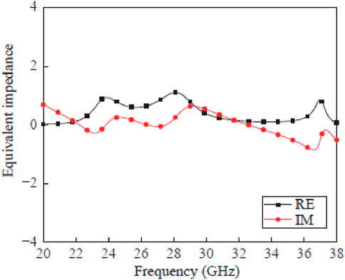
Figure 3. Equivalent impedance evaluation with real and imaginary parts.
Metamaterial is a composite artificial material that is microscopically inhomogeneous, but can be regarded as a uniform dielectric material from the subwavelength scale. Therefore, equivalent medium theory can be used for analysis. The calculation formulas of equivalent dielectric constant and equivalent magnetic permeability are as follows (Holloway et al., 2012) in Eqs 6, 7
In the formula:
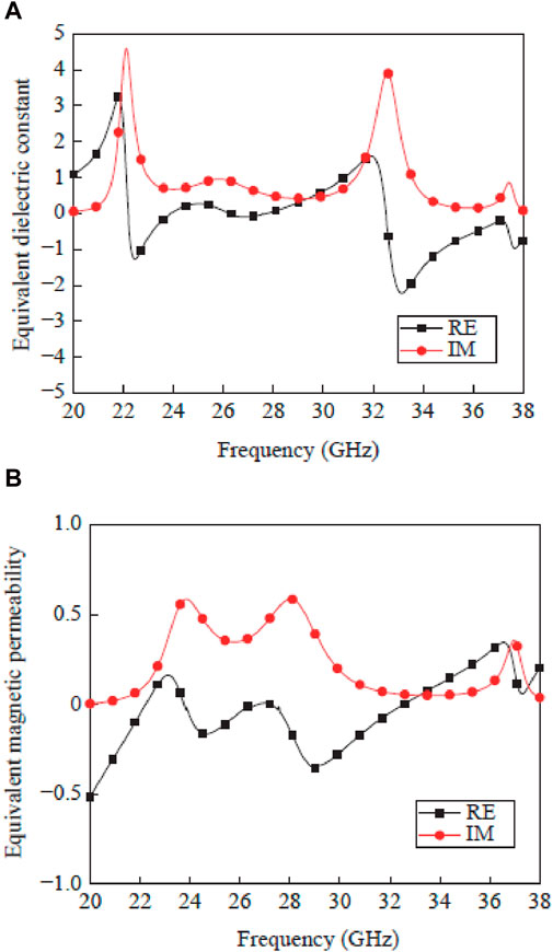
Figure 4. Evaluation of real and imaginary parts of equivalent parameters. (A) Dielectric constant; (B) permeability.
When electromagnetic waves are incident on the metamaterial surface structure, an induced current will be excited, and the metamaterial structure will form a current path, which forms an equivalent circuit model. Among them, each open split ring structure can be equivalent to an RLC branch, and the equivalent parameters can be calculated according to the following formula (Silva et al., 2020) in Eqs 8–14
Where,
The three square resonant rings of the designed surface pattern of the metamaterial structure can be equivalent to three sets of RLC series branches, in which the capacitance is composed of the equivalent capacitance at the opening of the three resonant rings and the coupling capacitance between the inner and outer rings, C1, C2 and C3 are respectively generated by the mutual coupling of three rings from outside to inside in the metamaterial surface pattern and the opening of each ring itself (Zhang et al., 2024; Zhao et al., 2024). The inductance is excited by the induced current generated when electromagnetic waves are incident into the structure. L1, L2 and L3 are respectively induced by the three rings from the outside to the inside in the metamaterial surface pattern when electromagnetic waves are incident. Resistors R1, R2 and R3 are equivalently generated by the metal strip opening structure of three rings from outside to inside in the surface pattern. Therefore, the equivalent circuit model is shown in Figure 5. Among them, Z0 represents the free space impedance, Zh represents the equivalent impedance of the metamaterial dielectric substrate, and the three groups of parallel RLC branches correspond to the equivalent impedance parameters of the three resonant rings in the metamaterial surface structure.
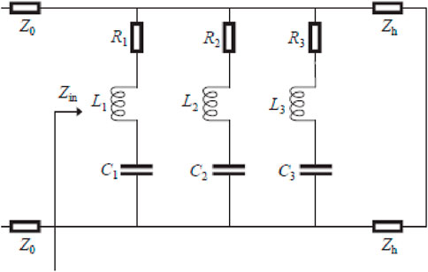
Figure 5. Circuit equivalent structure of metamaterial.
The metamaterial structure is analyzed based on the equivalent circuit theory. In order to simplify the calculation, all parameters are obtained based on the incident angle of 0°. The resistances R1, R2, and R3 calculated by the formula are 0.053 Ω, 0.033 Ω, and 0.013 Ω respectively. Inductors L1, L2, and L3 are 20.20 nH, 25.85 nH, and 19.00 nH respectively (Liao et al., 2022; Xu H. et al., 2023; Mou et al., 2023). Capacitors C1, C2, and C3 are 2.30 fF, 1.26 fF, and 0.95 fF respectively. Using the calculated parameter values combined with ADS software for optimization, the obtained simulated S-parameter curve is shown in Figure 6, which is basically consistent with the results obtained by CST simulation software.
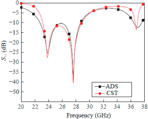
Figure 6. S-parameter evaluation using ADS and CST simulators.
To verify the effectiveness of high-frequency flexible transmission lines loaded with metamaterial structures for electromagnetic shielding, an SCPW transmission line operating in the 5G FR2 frequency band was designed for testing.
The segmented coplanar waveguide transmission line is redesigned based on the traditional coplanar transmission line, and a half-wavelength resonator is added to adjust the operating frequency of the transmission line (Ding et al., 2021), making the coplanar waveguide structure more suitable for high-frequency application scenarios.
The segmented coplanar waveguide transmission line is mainly composed of a coplanar waveguide part and a dielectric substrate, as shown in Figure 7A. The coplanar waveguide part consists of a signal line (I), a ground plane (II), and a half-wavelength resonator (III). As shown in Figure 7B, increasing the number of segmented coplanar waveguide units can freely adjust the overall length of the transmission line. In the segmented coplanar waveguide transmission line structure (Liu, 2021; Yang Y. et al., 2023), the coplanar waveguide part is made of metallic copper, the conductivity is 5.8 × 10⁷ S/m, the thickness is 0.018 mm, the dielectric substrate (IV) uses a dielectric constant of 3.5, and the loss tangent tan δ is 0.0027 Polyimide material, thickness is 0.05 mm, and other structural parameters are shown in Table 2. Because the SCPW transmission line uses ultra-thin copper film and flexible polyimide materials, it has good flexibility and can meet the needs of flexible electronic devices.
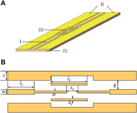
Figure 7. Illustration of segmented coplanar waveguide model. (A) Transmission line; (B) unit structure.
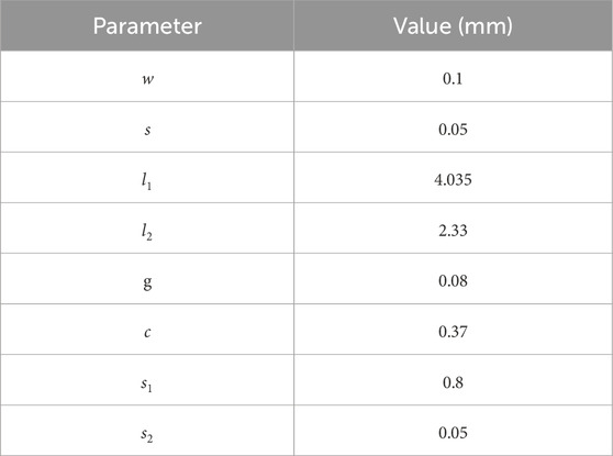
Table 2. Segmented coplanar waveguide parameters.
Metamaterial structures have good control and absorption capabilities for electromagnetic waves due to their extraordinary physical properties. By changing the constituent materials, they can also meet the flexibility needs of flexible electronic devices. Since high-frequency metamaterials can easily achieve ultra-thin thickness, they are closely related to high-frequency transmission lines have good adaptability. Unlike most traditional electromagnetic shielding methods that suppress radiation through reflection (Li et al., 2021; Jiang and Xu, 2023), the metamaterial structure has characteristics such as negative magnetic permeability and negative dielectric constant, and can control the transmission line by regulating and absorbing electromagnetic waves. It can achieve good shielding performance at high frequencies while reducing transmission loss and ensuring signal transmission quality.
The flexible transmission line shielding structure loaded with metamaterial structure consists of three parts, as shown in Figure 8, which are the transmission line, the dielectric spacer layer and the metamaterial shielding layer. Among them, the transmission line is placed at the bottom of the overall structure. The metamaterial shielding layer is located on the top layer and consists of an array of metamaterial structural units. Between the two is a dielectric spacer layer, which is used to isolate the upper and lower parts and form a certain distance between the transmission line and the metamaterial array to ensure that the metamaterial shielding structure can work normally.
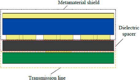
Figure 8. Transmission line model with metamaterial loading.
The metallic copper used in the metamaterial pattern and metal backplane has a conductivity of 5.8 × 10⁷ S/m and a thickness t1 of 0.018 mm. Polyimide material, having a thickness of t2 0.48 mm, a dielectric constant of 3.5, and a loss tangent tan δ of 0.0027, makes up the dielectric substrate. Since a metal backplane entirely encloses one side of the dielectric substrate, there is no electromagnetic wave transmission.
The overall structure of the segmented coplanar waveguide transmission line loaded with metamaterial is depicted in Figure 9A. From bottom to top are the segmented coplanar waveguide transmission line, dielectric spacer layer and metamaterial shielding layer. Among them, the segmented coplanar waveguide transmission line is consistent with the structural parameters introduced previously. The dielectric spacer layer is made of polyimide material with the same structure as the upper and lower layers, with a thickness of 0.15 mm, ensuring the flexibility of the overall structure. The metamaterial shielding layer is composed of 12 metamaterial units arranged along the signal transmission direction of the transmission line, as shown in Figure 9B.
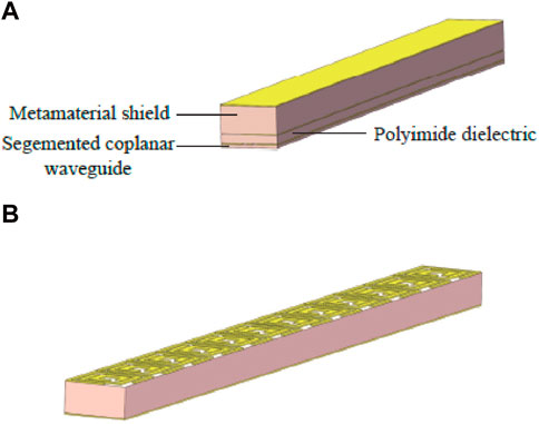
Figure 9. Segmented coplanar waveguide with metamaterial. (A) Segmented coplanar waveguide transmission line; (B) shielding layer of metamaterial.
The metamaterial structure can absorb the radiation of high-frequency flexible transmission lines and change the electromagnetic properties such as the amplitude, phase and polarization of the reflected components, so it has less impact on the transmission performance (Huang et al., 2023). The S-parameter comparison of the segmented coplanar waveguide transmission line before and after adding a metamaterial shielding structure is shown in Figure 10. Since the metamaterial structure regulates and absorbs the radiated electromagnetic waves of the transmission line, it effectively reduces the reflection component of the radiation wave. Compared with the segmented coplanar waveguide without a shielding structure, due to the parasitic capacitance and parasitic inductance generated by the coupling of the transmission line and the metamaterial structure, the operating frequency band of the metamaterial structure will be shifted to a certain extent, which in turn affects the transmission characteristics of the transmission line at 32–34 GHz. Moreover, the loss of the segmented coplanar waveguide transmission line increases significantly in some frequency bands, and the resonance point also moves toward the low frequency band. There is a certain offset, but it still maintains good transmission performance in the wide frequency bands of 23.49–30.96 GHz and 32.98–38.00 GHz.
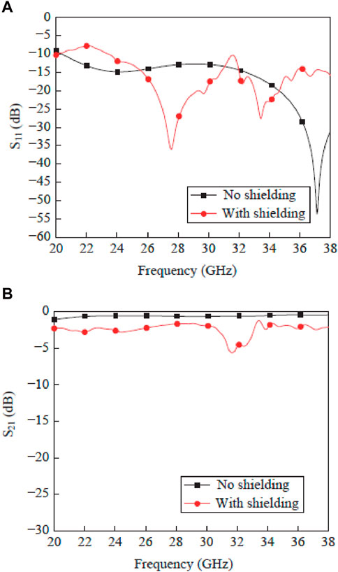
Figure 10. Performance comparison of S-parameters with and without metamaterial. (A) S11; (B) S21.
The designed metamaterial structure has a certain loss capability for electromagnetic waves, so in the working frequency band, it can efficiently suppress the electromagnetic radiation of flexible high-frequency transmission lines. Set up an electric field probe in the CST simulation software to simulate a 3 m far-field radiation test, and calculate the average value of the peak values in each radiation direction to analyze the shielding effectiveness (Huang et al., 2019; Huang et al., 2022). The comparison of the 3 m far-field electric field radiation intensity of the segmented coplanar waveguide transmission line before and after adding the metamaterial shielding structure is shown in Figure 11. To match the operating frequency of the metamaterial structure, the frequency range was limited to 22–29 GHz during the simulation test. It can be seen that, in this frequency band, the radiation intensity of segmented coplanar waveguide transmission lines without shielding structures is higher than −15 dB V/m, and the highest value is distributed near 22 GHz, which can reach −13.5 dB V/m. Therefore, when no shielding structure is loaded, the flexible segmented coplanar waveguide transmission line has a high radiation level in the operating frequency band. High-frequency radiation will have an irreversible impact on other components in the flexible PCB and affect the electromagnetic characteristics of the entire electronic system. A shielding structure needs to be designed to effectively suppress the radiation from segmented coplanar transmission lines. Use the following formula to calculate shielding effectiveness in Eq. 15
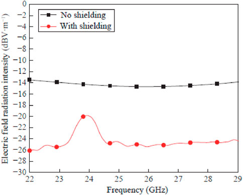
Figure 11. Electric field radiation intensity evaluation with and without metamaterial.
In the formula,
The metamaterial structure has a good inhibitory effect on the electromagnetic radiation of the transmission line. On the one hand, the metamaterial may modify the transmission line’s surface electric field distribution and effectively control electromagnetic waves. Figure 12 compares the segmented coplanar waveguide transmission line’s surface electric field distribution before and after the metamaterial shielding structure was added. Without shielding, the surface electric field value is still higher in the edge area of the ground line of the transmission line, and the amount of outward radiation is larger. After adding the shielding structure, the surface electric field distribution range has been reduced and is limited to the ground area of the segmented coplanar transmission line. Moreover, at the three frequencies of 23 GHz, 25 GHz and 27 GHz, the surface electric field peak value of the segmented coplanar waveguide transmission line was reduced by 3.0 dB mV/m, 2.6 dB mV/m and 0.8 dB mV/m respectively. On the other hand, cavities can be formed to confine electromagnetic waves within a shielding structure. The electric field distribution of the overall structure of the transmission line after loading the shielding structure was calculated, and the results are shown in Figure 13 (the frequency is set to 27 GHz). It can be seen that the electromagnetic waves are bound in the whole structure composed of the transmission line and the shielding array. The metamaterial structure utilizes the electromagnetic resonance effect regulates and absorbs electromagnetic radiation. As can be seen from Figure 13, the electric field distribution is confined to the desired level after utilization of metamaterial structure in the transmission line.
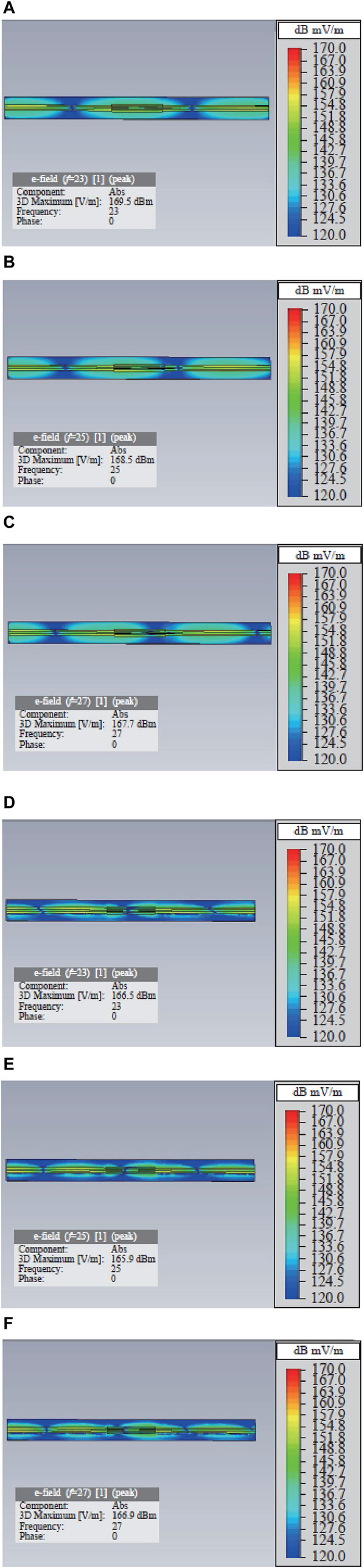
Figure 12. Surface electric field distribution at different frequencies with and without metamaterial. (A) 23 GHz (no shielding); (B) 25 GHz (no shielding); (C) 27 GHz (no shielding); (D) 23 GHz (with shielding); (E) 25 GHz (with shielding); (F) 27 GHz (with shielding).

Figure 13. Overall structure electric field distribution when frequency is 27 GHz.
After theoretical analysis and simulation, in order to further verify that the metamaterial structure has little impact on the flexibility and transmission properties of the segmented coplanar waveguide transmission line before and after loading the metamaterial shielding structure was processed, and the conductor copper was printed on the dielectric polyimide material with a constant of 3.5, the actual object is shown in Figure 14. Flexibility analysis was conducted on the actual object, and the images of the bending test proved that the flexibility of the flexible transmission line can still be maintained after using the metamaterial structure of the flexible dielectric substrate. To weld the high-frequency SMA adapter to connect the vector network analyzer for S-parameter measurement, a test transition structure is designed when processing various high-frequency flexible transmission lines.
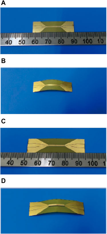
Figure 14. Proposed prototype. (A) no shield; (B) with test 1 bend; (C) with metamaterial; (D) with test 2 bend.
The processed segmented coplanar waveguide transmission line was tested, and the actual measurement environment is shown in Figure 15. The comparison of the measured and simulated S-parameters before and after adding the metamaterial shielding structure and with bending is shown in Figure 16. It can be seen that the transmission bandwidth of the two is basically the same, but the measured transmission loss has increased significantly. There are certain differences between the simulation and actual measurement results. On the one hand, there is a certain processing error due to insufficient process accuracy, which will cause parasitic parameters and impedance discontinuities in the transmission line structure, causing an increase in transmission loss. This effect occurs at high frequencies. On the other hand, the transition structure designed by welding SMA adapters, as well as high-frequency SMA adapters, will bring certain transmission losses. Furthermore, Figure 16 depicts that the measured and simulated reflection and transmission coefficients with and without bend (with shielding and without shielding) have approximately similar results which validated that the proposed structure enable stable performance in bending or none-bend position.
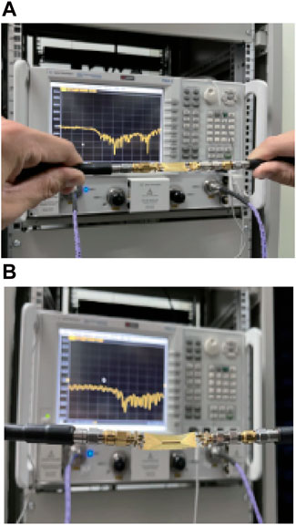
Figure 15. Experimental setup and analysis. (A) no shielding; (B) with metamaterial.
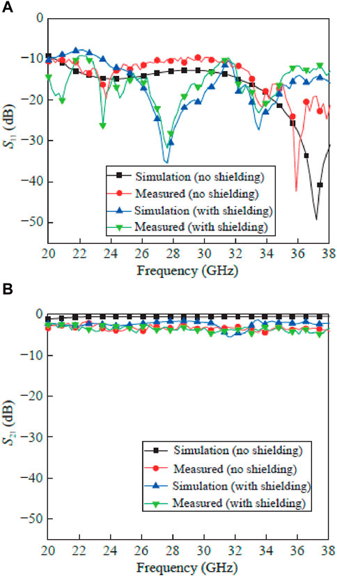
Figure 16. Comparison of simulation and measured results of the proposed structure with and without bend and shielding. (A) S11; (B) S21.
In addition, as shown in Table 3, compared with existing metamaterial structures, the structure designed in this paper is smaller in size and achieves good control over electromagnetic waves in a wide frequency band, so it has the characteristics of miniaturization and wide frequency band.
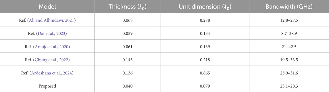
Table 3. Performance comparison of proposed and existing designs.
This paper proposes a low-reflection radiation shielding solution to address the electromagnetic interference problem of high-frequency flexible transmission lines, which uses metamaterial structures to regulate and absorb radiation waves. The overall structure consists of transmission lines, dielectric spacers and metamaterial shielding layers. The media are all made of flexible materials to ensure flexibility. To verify the effectiveness of the solution, a miniaturized broadband metamaterial structure operating at 23.10–28.30 GHz and a high-frequency transmission line with segmented coplanar waveguide characteristics operating were designed and tested. The results show that the metamaterial shielding array is effective for segmented coplanar waveguide transmission lines. The electric field radiation in the 3 m far field achieves an average shielding efficiency of 10.10 dB and a maximum shielding efficiency of 12.63 dB, with little impact on transmission quality. It can maintain transmission performance in the wide frequency bands of 23.49–30.96 GHz and 32.98–38.00 GHz. The metamaterial structure can also be miniaturized at high frequencies, with a thickness of only 0.04λ0, and the use of flexible dielectric substrates can ensure the flexibility of flexible transmission lines. Therefore, using metamaterial structures to suppress electromagnetic radiation has great application potential in high-frequency flexible electronic devices. Follow-up work can further study high-frequency transmission lines loaded with metamaterial shielding structures from the perspective of building theoretical models.
The original contributions presented in the study are included in the article/Supplementary Material, further inquiries can be directed to the corresponding authors.
IK: Data curation, Project administration, Software, Supervision, Visualization, Writing–original draft. AA: Formal Analysis, Investigation, Methodology, Resources, Validation, Writing–original draft. P-CW: Conceptualization, Data curation, Formal Analysis, Visualization, Writing–original draft. IH: Conceptualization, Funding acquisition, Project administration, Resources, Supervision, Writing–original draft.
The author(s) declare that financial support was received for the research, authorship, and/or publication of this article. This work was supported by Princess Nourah bint Abdulrahman University Researchers Supporting Project number (PNURSP 2024R435), Princess Nourah bint Abdulrahman University, Riyadh, Saudi Arabia. National Science and Technology Council 112-2811-E-005-011-MY2 and 112-2634-F-005-001-MBK.
The authors declare that the research was conducted in the absence of any commercial or financial relationships that could be construed as a potential conflict of interest.
All claims expressed in this article are solely those of the authors and do not necessarily represent those of their affiliated organizations, or those of the publisher, the editors and the reviewers. Any product that may be evaluated in this article, or claim that may be made by its manufacturer, is not guaranteed or endorsed by the publisher.
Albawri, S., Goh, H., Islam, M., Wong, H., Jamlos, M., Narbudowics, A., et al. (2020). Compact ultra-wideband monopole antenna loaded with metamaterial. Sensors 20 (3), 1–14. doi:10.3390/s20030796
Ali, H., and Alhindawi, M. (2021). A ultra-broadband thin metamaterial absorber for ku and K bands applications. J. Eng. 27 (5), 1–16. doi:10.31026/j.eng.2021.05.01
Alves, S., Babcinschi, M., Silva, A., Neto, D., Fonseca, D., and Neto, P. (2023). Integrated design fabrication and control of a bioinspired multimaterial soft robotic hand. Cyborg. Bionic. Syst. 4, 0051. doi:10.34133/cbsystems.0051
Araujo, J., Siqueira, G., Kemptner, E., Weber, M., Jun, C., and Mosso, M. M. (2020). An ultrathin and ultrawideband metamaterial absorber and an equivalent-circuit parameter retrieval method. IEEE. Trans. Antennas. Propag. 68 (5), 3739–3746. doi:10.1109/tap.2020.2963900
Ardeshana, M., Thakkar, F., and Domadia, S. (2024). Metamaterial-inspired absorber for GNSS and 5G pioneer spectrum band: achieving narrow bandwidth, wide incidence angle, and polarization agnostic. Photonics. Nanostr. – Fundam. Appl. 58, 101210–101213. doi:10.1016/j.photonics.2023.101210
Cao, K., Wang, B., Ding, H., Lv, L., Tian, J., Hu, H., et al. (2021). Achieving reliable and secure communications in wireless-powered NOMA systems. IEEE. Trans. Veh. Technol. 70 (2), 1978–1983. doi:10.1109/TVT.2021.3053093
Chen, B., Hu, J., Zhao, Y., and Ghosh, B. K. (2022). Finite-time velocity-free rendezvous control of multiple AUV systems with intermittent communication. IEEE. Trans. Syst. Man, Cybern. Syst. 52 (10), 6618–6629. doi:10.1109/TSMC.2022.3148295
Chen, C., Xi, B., Zhou, E., Peng, L., Chen, Z., and Gao, C. (2018). Porous graphene micro-flowers for high-performance microwave absorption. Nano-Micro. Lett. 10 (2), 26–11. doi:10.1007/s40820-017-0179-8
Chien, W., Cheng, Y., Hsiao, C., Han, K., and Chiu, C. (2020). Research on anti-radiation noise interference of high definition multimedia interface circuit layout of a laptop. Electronics 9 (3), 426–514. doi:10.3390/electronics9030426
Chung, M., Jeong, H., Kim, Y., Lim, S., and Baek, C. (2022). Design and fabrication of millimeter-wave frequency-tunable metamaterial absorber using MEMS cantilever actuators. Micromachines 13 (8), 1354–1415. doi:10.3390/mi13081354
Dai, H., Li, S., Dong, P., and Ma, Y. (2023). Design of an ultra-wideband transparent wave absorber. Materials 16 (17), 5962–6015. doi:10.3390/ma16175962
Dai, M., Luo, L., Ren, J., Yu, H., and Sun, G. (2022). PSACCF: prioritized online slice admission control considering fairness in 5G/B5G networks. IEEE. Trans. Netw. Sci. Eng. 9 (6), 4101–4114. doi:10.1109/TNSE.2022.3195862
Dai, M., Sun, G., Yu, H., and Niyato, D. (2024). Maximize the long-term average revenue of network slice provider via admission control among heterogeneous slices. IEEE/ACM Trans. Netw. 32 (1), 745–760. doi:10.1109/TNET.2023.3297883
Ding, F., Dai, J., Chen, Y., Zhu, J., Jin, Y., and Bozhevolnyi, S. I. (2016). Broadband near-infrared metamaterial absorbers utilizing highly lossy metals. Sci. Rep. 6 (1), 39445–39515. doi:10.1038/srep39445
Ding, Y., Zhang, W., Zhou, X., Liao, Q., Luo, Q., and Ni, L. M. (2021). FraudTrip: taxi fraudulent trip detection from corresponding trajectories. IEEE. Internet. Things. J. 8 (16), 12505–12517. doi:10.1109/JIOT.2020.3019398
Fu, B., Wan, G., Ma, X., Chen, Y., and Jiao, X. (2023). A 2.5-D miniaturized metamaterial absorber with minimal frequency deviation at large incident angles for both TE and TM modes at low frequency. Opt. Commun. 537, 129471–129514. doi:10.1016/j.optcom.2023.129471
Gao, N., Liu, J., Deng, J., Chen, D., Huang, Q., and Pan, G. (2024). Design and performance of ultra-broadband composite meta-absorber in the 200Hz-20kHz range. J. Sound. Vib. 574, 118229. doi:10.1016/j.jsv.2023.118229
Gao, P., Sun, J., Li, W., Su, C., Sun, Z., Xia, F., et al. (2023). Multifunctional and dynamically tunable coherent perfect absorber based on InSb and graphene metasurface. Results. Phys. 52, 106797–106811. doi:10.1016/j.rinp.2023.106797
Gupta, A., Bansal, B., Mishra, V., and Agrawal, A. (2020). Miniaturised tri-band rhombus-shaped metamaterial-inspired antenna with gain enhancement using complementary closed ring resonators. IET Microwaves, Antennas Propag. 14 (2), 185–193. doi:10.1049/iet-map.2019.0567
He, T., Zheng, Y., Liang, X., Li, J., Lin, L., Zhao, W., et al. (2023). A highly energy-efficient body-coupled transceiver employing a power-on-demand amplifier. Cyborg. Bionic. Syst. 4, 0030. doi:10.34133/cbsystems.0030
Holloway, C., Kuester, E., Gordon, J., O’Hara, J., Booth, J., and Smith, D. R. (2012). An overview of the theory and applications of metasurfaces: the two-dimensional equivalents of metamaterials. IEEE. Antennas. Propag. Mag. 54 (2), 10–35. doi:10.1109/map.2012.6230714
Hossain, M., Rahman, M., and Faruque, M. (2023). An innovative polarization-insensitive perfect metamaterial absorber with an octagonal-shaped resonator for energy harvesting at visible spectra. Nanomaterials 13 (12), 1–13.
Hu, J., Wu, Y., Li, T., and Ghosh, B. K. (2019). Consensus control of general linear multiagent systems with antagonistic interactions and communication noises. IEEE. Trans. Automatic. Control. 64 (5), 2122–2127. doi:10.1109/TAC.2018.2872197
Huang, X., Zhang, X., Zhou, L., Xu, J., and Mao, J. (2023). Low-loss self-packaged ka-band LTCC filter using artificial multimode SIW resonator. IEEE. Trans. Circuits Syst. II Express. Briefs. 70 (2), 451–455. doi:10.1109/TCSII.2022.3173712
Huang, X., Zhou, L., Xu, J., Zhang, X. Y., and Mao, J. (2022). BCB-based thin-film ka-band quarter-mode SIW packaged filters with ultrawide stopband and independently controlled TZs. IEEE. Trans. Microw. Theory. Tech. 70 (10), 4389–4398. doi:10.1109/TMTT.2022.3197589
Huang, X., Zhou, L., Yuan, Y., Qiu, L., and Mao, J. (2019). Quintuple-Mode W-band packaged filter based on a modified quarter-mode substrate-integrated waveguide cavity. IEEE. Trans. Components, Packag. Manuf. Technol. 9 (11), 2237–2247. doi:10.1109/TCPMT.2019.2925371
Jiang, Y., and Li, X. (2022). Broadband cancellation method in an adaptive co-site interference cancellation system. Int. J. Electron. 109 (5), 854–874. doi:10.1080/00207217.2021.1941295
Jiang, Z., and Xu, C. (2023). Disrupting the technology innovation efficiency of manufacturing enterprises through digital technology promotion: an evidence of 5G technology construction in China. IEEE. Trans. Eng. Manag. 71, 6918–6928. doi:10.1109/TEM.2023.3261940
Lei, X., Li, Y., Huo, S., Sun, Z., Yu, H., Fang, L., et al. (2022). Design and analysis of a novel compact metamaterial absorber based on double-layer ITO resistive film for improving signal integrity. IEEE Access 10, 24067–24079. doi:10.1109/access.2022.3155234
Li, M., Wang, T., Chu, F., Han, Q., Qin, Z., and Zuo, M. J. (2021). Scaling-basis chirplet transform. IEEE. Trans. Industrial. Electron. 68 (9), 8777–8788. doi:10.1109/TIE.2020.3013537
Li, M., Wei, R., Zhang, Z., Zhang, P., Xu, G., and Liao, W. (2023b). CVT-based asynchronous BCI for brain-controlled robot navigation. Cyborg. Bionic. Syst. 4, 0024. doi:10.34133/cbsystems.0024
Li, Y., Wang, J., Zhu, R., Sui, S., Han, Y., Ding, C., et al. (2023a). Reconfigurable phase-modulated metasurfaces via rotating adjustable resistor. Results. Phys. 47, 106378–106414. doi:10.1016/j.rinp.2023.106378
Liao, Q., Chai, H., Han, H., Zhang, X., Wang, X., Xia, W., et al. (2022). An integrated multi-task model for fake news detection. IEEE. Trans. Knowl. Data. Eng. 34 (11), 5154–5165. doi:10.1109/TKDE.2021.3054993
Liu, D., Cao, Z., Jiang, H., Zhou, S., Xiao, Z., and Zeng, F. (2022). Concurrent low-power listening: a new design paradigm for duty-cycling communication. ACM Trans. Sen. Netw. 19 (1), 1–24. doi:10.1145/3517013
Liu, G. (2021). Data collection in MI-assisted wireless powered underground sensor networks: directions, recent advances, and challenges. IEEE Commun. Mag. 59 (4), 132–138. doi:10.1109/MCOM.001.2000921
Liu, J., Yu, M., Yu, Z., and Nicolosi, V. (2023). Design and advanced manufacturing of electromagnetic interference shielding materials. Materialstoday 66, 245–272. doi:10.1016/j.mattod.2023.03.022
Mou, J., Gao, K., Duan, P., Li, J., Garg, A., and Sharma, R. (2023). A machine learning approach for energy-efficient intelligent transportation scheduling problem in a real-world dynamic circumstances. IEEE. Trans. Intelligent Transp. Syst. 24 (12), 15527–15539. doi:10.1109/TITS.2022.3183215
Norouzi, M., Jarchi, S., Miab, M., Esfandiari, M., Lalbakhsh, A., Koziel, S., et al. (2023). 3D metamaterial ultra-wideband absorber for curved surface. Sci. Rep. 13 (1043), 1–15.
Perdigones, F., and Quero, J. (2022). Printed circuit boards: the layer’s functions for electronic and biomedical engineering. Micromachines 13 (3), 460–513. doi:10.3390/mi13030460
Shallah, A., Zubir, F., Rahim, M., Jizat, N., Basit, A., Assaad, M., et al. (2024). A miniaturized metamaterial-based dual-band 4 × 4 butler matrix with enhanced frequency ratio for sub-6 GHz 5G applications. IEEE Access 12, 32320–32333. doi:10.1109/access.2024.3371027
Silva, B., Campos, A., and Neto, A. (2020). Equivalent circuit model for analysis of frequency selective surfaces with ring and double concentric ring apertures. IET Microwaves, Antennas. Propag. 14 (7), 600–607. doi:10.1049/iet-map.2019.0760
Suarez, A., Victoria, J., Torres, J., Martinez, P., Alcarria, A., Perez, J., et al. (2020). Performance study of split ferrite cores designed for EMI suppression on cables. Electronics 9 (12), 1992–2016. doi:10.3390/electronics9121992
Sun, G., Xu, Z., Yu, H., and Chang, V. (2021). Dynamic network function provisioning to enable network in box for industrial applications. IEEE. Trans. Industrial. Inf. 17 (10), 7155–7164. doi:10.1109/TII.2020.3042872
Tian, N., Wang, C., and You, C. (2023). Synthesis of nanospherical CoFe2O4/Ti3C2Tx MXene composites with enhanced microwave absorbing performance. J. Alloys. Compd. 967, 171796–171815. doi:10.1016/j.jallcom.2023.171796
Wang, J., Or, S., and Tan, J. (2018). Enhanced microwave electromagnetic properties of core/shell/shell-structured Ni/SiO2/polyaniline hexagonal nanoflake composites with preferred magnetization and polarization orientations. Mater. Des. 153, 190–202. doi:10.1016/j.matdes.2018.05.007
Wang, L., Yang, J., Cheng, W., Zou, J., and Zhao, D. (2021). Progress on polymer composites with low dielectric constant and low dielectric loss for high-frequency signal transmission. Front. Mater. 8, 1–12. doi:10.3389/fmats.2021.774843
Wang, Q., Hu, J., Wu, Y., and Zhao, Y. (2023b). Output synchronization of wide-area heterogeneous multi-agent systems over intermittent clustered networks. Inf. Sci. 619, 263–275. doi:10.1016/j.ins.2022.11.035
Wang, Q., Li, P., Rocca, P., Li, R., Tan, G., Hu, N., et al. (2023a). Interval-based tolerance analysis method for petal reflector antenna with random surface and deployment errors. IEEE. Trans. Antennas Propag. 71 (11), 8556–8569. doi:10.1109/TAP.2023.3314097
Wu, H., Liu, J., and Liang, S. (2020). Sandwitch-like Fe3O4/Fe3S4 composites for electromagnetic wave absorption. Chem. Eng. J. 393 (124743), 1–15.
Wu, T., Zhang, X., Xu, Q., Plum, E., Chen, K., Xu, Y., et al. (2022). Dielectric metasurfaces for complete control of phase, amplitude, and polarization. Adv. Opt. Mater. 10 (1), 1–13. doi:10.1002/adom.202101223
Xie, Y., Liu, S., Huang, K., Chen, B., Shi, P., Chen, Z., et al. (2022). Ultra-broadband strong electromagnetic interference shielding with ferromagnetic graphene quartz fabric. Adv. Mater. 34 (30), e2203015. doi:10.1002/adma.202202982
Xu, G., Zhang, Q., Song, Z., and Ai, B. (2023a). Relay-Assisted deep space optical communication system over coronal fading channels. IEEE. Trans. Aerosp. Electron. Syst. 59 (6), 8297–8312. doi:10.1109/TAES.2023.3301463
Xu, H., Han, S., Li, X., and Han, Z. (2023b). Anomaly traffic detection based on communication-efficient federated learning in space-air-ground integration network. IEEE. Trans. Wirel. Commun. 22 (12), 9346–9360. doi:10.1109/TWC.2023.3270179
Xu, P., and Shin, I. (2024). Preparation and performance analysis of thin-film artificial intelligence transistors based on integration of storage and computing. IEEE Access 12, 30593–30603. doi:10.1109/ACCESS.2024.3369171
Yang, H., Xiong, Z., Zhao, J., Niyato, D., Wu, Q., Poor, H., et al. (2020). Intelligent reflecting surface assisted anti-jamming communications: a fast reinforcement learning approach. IEEE. Trans. Wirel. Commun. 20 (3), 1963–1974. doi:10.1109/twc.2020.3037767
Yang, M., Cai, C., Wang, D., Wu, Q., Liu, Z., and Wang, Y. (2023a). Symmetric differential demodulation-based heterodyne laser interferometry used for wide frequency-band vibration calibration. IEEE. Trans. Industrial. Electron. 71, 8132–8140. doi:10.1109/TIE.2023.3299015
Yang, Y., Wei, X., Yao, W., and Lan, J. (2023b). Broadband electrical impedance matching of sandwiched piezoelectric ultrasonic transducers for structural health monitoring of the rail in-service. Sensors. Actuators. A Phys. 364, 114819. doi:10.1016/j.sna.2023.114819
Zhang, X., Deng, H., Xiong, Z., Liu, Y., Rao, Y., Lyu, Y., et al. (2024). Secure routing strategy based on attribute-based trust access control in social-aware networks. J. Signal. Process. Syst. 96, 153–168. doi:10.1007/s11265-023-01908-1
Zhang, Y., Zhao, P., Lu, Q., Zhang, Y., Lei, H., Yu, C., et al. (2023). Functional additive manufacturing of large-size metastructure with efficient electromagnetic absorption and mechanical adaptation. Compos. Part A Appl. Sci. Manuf. 173, 107652. doi:10.1016/j.compositesa.2023.107652
Zhao, L., Qu, S., Xu, H., Wei, Z., and Zhang, C. (2024). Energy-efficient trajectory design for secure SWIPT systems assisted by UAV-IRS. Veh. Commun. 45, 100725. doi:10.1016/j.vehcom.2023.100725
Keywords: metamaterial absorber, electromagnetic radiation, miniaturization, 5G waveguide, dielectric structure
Citation: Khan I, Alshehri A, Wang P-C and Hameed IA (2024) Design and performance evaluation of a compact radiation absorber for 5G applications. Front. Mater. 11:1428912. doi: 10.3389/fmats.2024.1428912
Received: 07 May 2024; Accepted: 01 July 2024;
Published: 31 July 2024.
Edited by:
Ugur Cem Hasar, University of Gaziantep, TürkiyeReviewed by:
Sudhakar Sahu, KIIT University, IndiaCopyright © 2024 Khan, Alshehri, Wang and Hameed. This is an open-access article distributed under the terms of the Creative Commons Attribution License (CC BY). The use, distribution or reproduction in other forums is permitted, provided the original author(s) and the copyright owner(s) are credited and that the original publication in this journal is cited, in accordance with accepted academic practice. No use, distribution or reproduction is permitted which does not comply with these terms.
*Correspondence: Pi-Chung Wang, cGN3YW5nQG5odS5lZHUudHc=
Disclaimer: All claims expressed in this article are solely those of the authors and do not necessarily represent those of their affiliated organizations, or those of the publisher, the editors and the reviewers. Any product that may be evaluated in this article or claim that may be made by its manufacturer is not guaranteed or endorsed by the publisher.
Research integrity at Frontiers
Learn more about the work of our research integrity team to safeguard the quality of each article we publish.