 Yunlin Liu1,2
 Shangwei Huo
- 1Anhui Jianzhu University, Prefabricated Building Research Institute of Anhui Province, Hefei, China
- 2College of Civil Engineering, Anhui Jianzhu University, Hefei, China
- 3Anhui Construction Engineering Testing Technology Group Co., Ltd., Hefei, China
- 4Shandong Jianzhu University, Jinan, China
- 5School of Mechanical and Electrical Engineering, Anhui Jianzhu University, Hefei, China
With the great development of the construction industry, prefabricated building components have been greatly developed. To study the compressive performance of the new wallboard, the axial compression performance test of six full-scale new lattice wallboards was carried out in this paper. The failure mode, axial pressure-displacement relationship curve, axial compression bearing capacity, and axial pressure-strain relationship of the wallboard were obtained through the experiments. This reveals the influence of the thickness of the concrete surface and the number of ribs on the performance of the wallboard. The test results show that the ultimate bearing capacity of the specimen increases with the increase of the thickness of the concrete surface layer with the same number of ribs. Specimen DW -30 increased by 4% over DW -20 and DW -50 increased by 41.6% over DW -30. The ultimate bearing capacity of the three-ribbed specimens was higher than that of the two-ribbed specimens for the same concrete face thickness, about 1.11 times that of the two-ribbed specimens. The concrete facing thickness and the number of ribs have a restraining effect on the deformation of the wallboard. Additionally, the calculation formula of axial bearing capacity of type latticed wallboard considering the influence of eccentric compression was proposed, which can provide a reference for engineering calculation.
1 Introduction
The state strongly supports the construction of beautiful villages, and the change in rural housing construction is imminent. Prefabricated housing integrates environmental protection, energy saving, emission reduction, and comfort, which is the direction of development for rural green housing. Prefabricated wallboards can improve the seismic resistance of urban houses while having small quality, taking into account heat insulation, sound insulation, and other functions (Chen et al., 2022; Hou et al., 2023). Presently, domestic and foreign research and development of many new wallboards that can be used for load-bearing, thermal insulation, and sound insulation, as well as their compression performance, have been studied (Zhang et al., 2017; Mo et al., 2022).
Benayoune et al. (Benayoune et al., 2007), through the precast concrete composite wallboard for axial compression study, gave composite wallboard axial compression semi-empirical formula. Yuno Xu et al. (Xu and Chen, 2022) conducted an experimental study on the compressive properties of 6-sided BFRP grid-reinforced geopolymer concrete sandwich walls, 1-sided BFRP reinforced geopolymer concrete sandwich walls, and 1-sided reinforced concrete sandwich walls, respectively. The results showed that the BFRP material has a low modulus of elasticity and that the enhancement of the axial compressive load capacity of the concrete sandwich wall is lower than that of an ordinary steel bar. Zhang Xizhi et al. (Zhang et al., 2022) conducted vertical axial compression tests on five full-size load-bearing, heat-insulation-integrated precast wallboard bays. They investigated the effects of opening, height-thickness ratio, and loading method on the compressive properties of the wallboard, such as modes of disruption, load-bearing capacity, and crack development under axial compression. Dong Jing et al. (Dong and Fan, 2019) conducted axial compression tests on precast lightweight concrete wallboard with different thicknesses and height-to-thickness ratios. They established the formula for calculating the vertical bearing capacity of the wallboard under axial loading.
Wang Jingfeng et al. (Wang et al., 2021) developed a prefabricated cold-formed steel composite wall panel filled with lightweight slurry and conducted axial compression tests on six pieces of full-scale composite wallboard. The results showed that the presence or absence of cladding, slurry type, and slurry thickness have a more significant effect on the axial compression performance of the combined wallboard; the number of wire mesh layers has no significant effect on the axial compression performance of the wallboard. Axial compressive performance test and load capacity calculation method for prefabricated cold-formed steel composite wallboard filled with lightweight slurry. Alessandro Grazzini et al. (Grazzini et al., 2020) investigated the delamination fracture patterns of wall facings and confirmed the stick-slip behaviour, affecting the overall performance of the walls. Abdul Aziz Abdul Samad (Jayaprakash et al., 2008; Mohamad et al., 2012; Goh et al., 2016; Mohamad et al., 2017) team studied the precast lightweight foam concrete sandwich panel (PFLP). The wall was found to be in a composite state under compression, and the semi-empirical formula for predicting the ultimate bearing capacity of the sandwich wall was predicted. Incorporating lightweight materials such as foam concrete inside the wall panels can enhance the insulation performance of the wall panels (Liu et al., 2023a; Liu et al., 2023b). R.K.L.Su et al. (Su and Wong, 2007) conducted an experimental study on three reinforced concrete walls and found that the axial load ratio has a significant effect on the deformation capacity, bearing capacity, and failure mode of the wall panels.
Wang Wanqian et al. (Wang et al., 2020) proposed a prediction formula for the axial bearing capacity of cold formed steel composite walls sprayed with lightweight polymer material, which was verified by test data. The combined performance of infill walls has been studied, and experiments have revealed that explicit consideration of the out-of-plane behavior and damage of exterior infill walls is required to provide a good estimate of the location and occurrence of shear damage to structural elements (Bikçe et al., 2021; Del Zoppo et al., 2021; Donà et al., 2022) Zhang Xiaomeng et al. conducted axial compression tests on a composite insulated concrete sandwich (ICS) wall, and the results showed that the ICS wall has excellent axial compressive resistance and high stability. Fiber materials are widely used for structural reinforcement and new structure construction (Guo et al., 2023a; Guo et al., 2023b).
However, in practical engineering, traditional light steel houses with cold-formed steel walls often need help with sound insulation, thermal insulation, and limited bearing capacity (Yang, 2021). The inner and outer leaf wallboards of the combined sandwich wallboard cannot bear the force together, and the performance of the wallboard is greatly affected by the performance of the connectors (Liu et al., 2022). The assembled lattice wallboard has excellent stiffness and elasticity and also has the advantages of low cost, convenient transportation, installation, and construction. On this basis, this paper proposes a new type of assembled lattice wallboard: the core mold made of straw glass magnesium plate is filled in its interior, and reinforced concrete is poured between adjacent boxes to form rib beams and rib columns. The wall is arranged with steel mesh and rib reinforcement spot welding, and the concrete panel is poured to form a new type of assembled wallboard with load-bearing, lightweight, thermal insulation, and sound insulation. A few scholars have conducted experimental research on the compressive and seismic performance of lattice wallboards. Lu et al. (Lu and Xue, 2013) analyzed the mechanical performance of lattice foam concrete energy-saving walls and conducted horizontal low cyclic loading tests on two groups of specimens. Cao Qikun et al. (Cao et al., 2018) conducted an axial compression test study on five cemented polystyrene molded shell lattice-type concrete walls. The results showed that the damage process was similar for each specimen under axial compression, and the wall’s ultimate bearing capacity increased with the longitudinal reinforcement ratio. Ali Jalaeefar et al. (Jalaeefar and Zargar, 2020; Borsaikia et al., 2021; Furtado et al., 2021) studied the seismic performance, structural stiffness, and damage evolution of infilled walls through experiments and numerical simulations. There are few studies on the axial compression performance of the core mold wallboard made of an internal straw glass magnesium plate at home and abroad.
Due to the obvious size effect of concrete, the dimensional characteristics of the structure and the effect of reinforcement rate on the performance of the structure also need to be considered in the design of the specimens (Accornero et al., 2021; Accornero et al., 2022; Carpinteri et al., 2022; Gallina, 2023). This paper conducts experiments on six full-scale wallboards to investigate the new lattice wallboards’ axial compression performance and bearing capacity. By analyzing the failure modes, axial pressure-displacement relationship curves, axial compressive bearing capacity, and axial pressure-strain relationship of the wallboard, the effects of the thickness of the concrete face layer and the number of ribs on the performance of the wallboards were obtained. A formula for calculating the bearing capacity of the new wallboards was proposed.
2 Test overview
2.1 Specimen design
In this experiment, six full-scale specimens were designed and composed of three parts: loading beam, wall, and ground beam. The wallboard’s height is 3000mm, and the width is 1180 mm (double-ribbed wallboard) DW and 1220 mm (three-ribbed wallboard) TW. The thickness of the wallboard is 200 mm, and the thickness of the concrete surface is 20 mm, 30 mm, and 50 mm, respectively. The vertical rib reinforcement extends into the ground beam and the loading beam. The design parameters of the specimen are shown in Table 1. The HRB400 steel bar with a diameter of 6 mm is used for the steel mesh. The specimen size and reinforcement diagram are shown in Table 1; Figure 1. The specimen fabrication and installation process is shown in Figure 2.
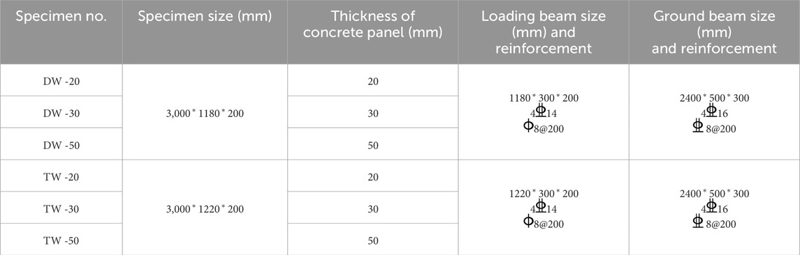
Table 1. Design parameters of specimens.
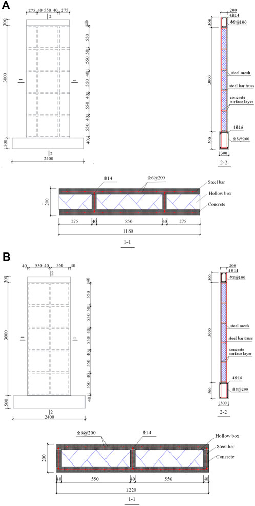
Figure 1. Specimen geometry and reinforcement: (A) double-ribbed specimen reinforcement diagram; (B) three-ribbed specimen reinforcement diagram.
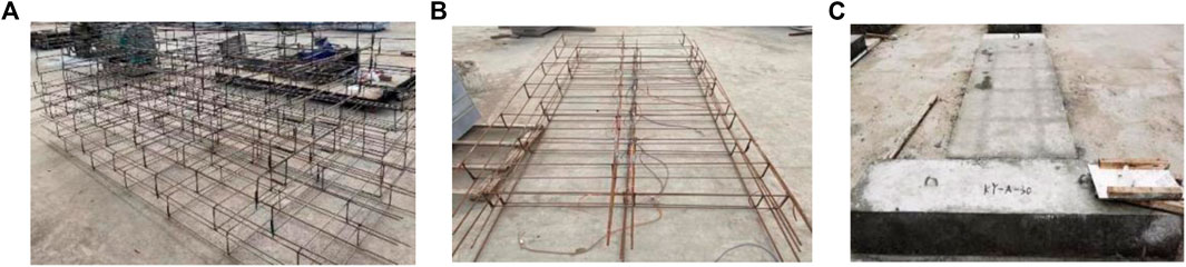
Figure 2. Fabrication of specimens: (A) making steel skeleton; (B) paste steel strain gauge; (C) maintenance specimen.
2.2 Material properties
The material properties of concrete are measured using standard cubic specimens cured under the same conditions as the concrete specimens in the test, according to the test method of “Standard for Test Method of Concrete Structures” GB/T 50152 (GB/T50152-2012, 2012). Reinforcing steel material properties were tested by intercepting three 600 mm long specimens, and the yield strength and ultimate strength of each steel bar were measured according to the “Metallic Materials - Tensile Testing - Part 1: Method of Test at Room Temperature” (GB/T 228.1-2010, 2010). The properties of each test material are shown in Tables 2, 3. The core molds were provided by Anhui Grid Material Technology Co. Three 500 × 500 × 300 mm core molds made at the same time were immersed for 48 h and then subjected to a local compressive test. The results showed that its compressive strength was ≥1.0MPa, and there was no penetrating crack or breakage on the surface. The compressive bearing capacity of the core mold is 1kN, and the core mold has little effect on the resistance of the wall. Therefore, the contribution of the core mold to the bearing capacity of the specimen was not considered in the following theoretical calculation.

Table 2. Material properties of concrete.
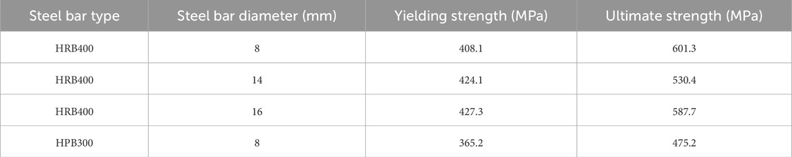
Table 3. Material properties of steel bar.
2.3 Loading device and loading scheme
The test was loaded through a JAW-2000J multi-channel electro-hydraulic servo system. The test device is mainly composed of the vertical actuator, reaction frame, pressure beam, and ground anchor, as shown in Figure 3. The pressure beam and the anchor bolt fix the vertical direction of the specimen. The specimens were loaded by uniform loading. The ultimate bearing capacity of the specimen was estimated according to the “Code for Design of Concrete Structures:” (GB 50010, 2010) before loading. The test loading was divided into two parts: pre-loading and failure loading. Pre-loading was divided into three levels, each level plus 5% of the ultimate bearing capacity of the budget load. Unloading was also divided into three levels. After the pre-loading, the formal loading began. Each level applied 5% of the budgeted ultimate bearing capacity. After loading to 70% of the budget’s ultimate bearing capacity, each stage’s ultimate bearing capacity was 3%. The load holding time after each stage of loading (unloading) was at least 3 minutes (Luo, 2008). The test was terminated when the load-bearing capacity decreased to 85% of the peak load or the specimen was destroyed.
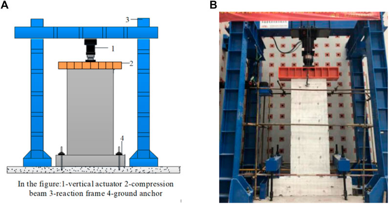
Figure 3. Test loading device diagram: (A) Loading schematic; (B) Loading device photos.
2.4 Measurement point layout and test content
The arrangement of the displacement meter is shown in Figure 4. Seven displacement gauges D1∼D7 were arranged for each specimen. Among them, D1∼D5 were arranged at equal spacing on the wall panel for measuring the out-of-plane bending deformation of different parts of the wall panel during the loading process; D6 and D7 were used to measure the axial displacement of the specimen during the loading process. The arrangement of the strain gauges is shown in Figure 5. The double-ribbed wallboard was arranged with six strain gauges at equal spacing along the two vertical ribs, and the front and back sides were symmetrically arranged. Among them, S (1,13), S (2,14), S (3,15), S (4,16), S (5,17), S (6,18), S (7,19), S (8,20), S (9,21), S (10,22), S (11,23), and S (12,24) were used to measure the change of concrete stress respectively. The reinforcement strain gauges were arranged symmetrically along the reinforcement skeleton. Among them, C (1,11), C (2,12), C (3,13), C (4,14), C (5,15), C (6,16), C (7,17), C (8,18), C (9,19), and C (10,20) were measured for the reinforcement stress changes respectively. The three-ribbed wallboard was arranged with six strain gauges at equal spacing along the vertical center rib direction, and the front and back sides were symmetrically arranged. Among them, S (1,7), S (2,8), S (3,9), S (4,10), S (5,11), and S (6,12) were used to measure the concrete stress changes respectively. The reinforcement strain gauges were arranged symmetrically along the reinforcement skeleton. Among them, C (1,6), C (2,7), C (3,8), C (4,9), C (5,10) were measured for the reinforcement stress changes respectively.
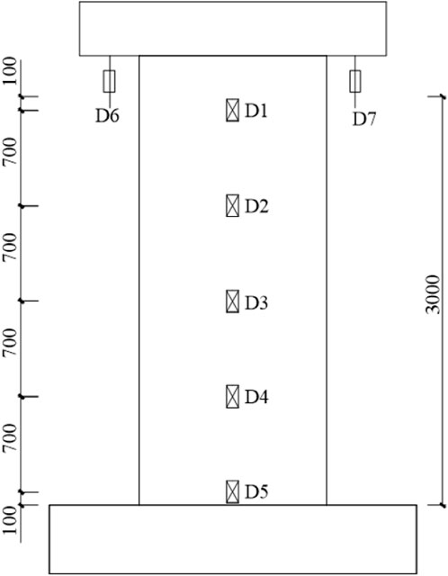
Figure 4. Displacement meter layout.
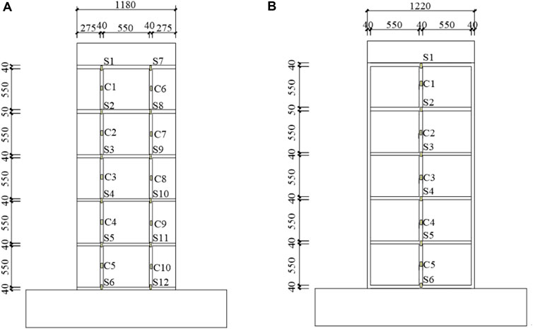
Figure 5. Strain gauge arrangement: (A) Strain gauge arrangement for double-ribbed specimens; (B) Strain gauge arrangement for three-ribbed specimens.
3 Test phenomena and failure characteristics
3.1 Specimen DW-20, DW-30 and DW-50
The specimens DW-20, DW-30, and DW-50 are double-ribbed specimens, which show similar failure modes in the test. No apparent phenomenon was observed in the specimens at the beginning of loading. The out-of-plane displacement of the specimens increased gradually with the increase of loading. Continuing loading, tiny cracks appeared in different parts of the specimens. When loaded to 700 kN–750 kN, non-structural transverse cracks appeared in the lower part of the loaded beams of specimens DW-20 and DW-30 at about 65 cm, and the length of the cracks was about 1 m. There was no apparent phenomenon in specimen DW-50. When loaded to 850 kN–900 kN, the first crack of specimens DW-20 and DW-30 extended a diagonal crack and expanded to the upper right along the wall. The surface concrete bulged out about 10 cm below the loading beam on the right side of the wallboard in front of specimen DW-50, with a length of about 40 cm.
Meanwhile, two vertical cracks appeared at the junction of the loading beam and the wall panel of all three specimens, with a crack length of about 20 cm. When loaded to 1000 kN–1100kN, the cracks in specimens DW-20 and DW-30 were widened and lengthened, and most of the cracks developed into transverse penetration joints. The growth rate of out-of-plane displacement became faster, at which time the core mold inside the wall panel was crushed. The same phenomenon was observed for specimen DW-50 loaded to 1400 kN.
When loaded to 1175.5kN, the vertical displacement of specimen DW-20 changed abruptly, and the wall panel was crushed. The concrete spalled off at the joint between the loading beam and the wall panel, and the upper concrete of the wall was peeled off from the lightweight module. The entire wallboard was crushed at approximately 4 cm from the bottom of the panel, and the longitudinal reinforcement was bent. When loaded to 1222.5kN, the wall panel of specimen DW -30 was crushed. The concrete spalled at the joint between the loading beam and the wallboard and the entire wallboard spalled at the front of the wall at the loading beam from the first crack. Loaded to 1700 kN, specimen DW-50 was destroyed, and the failure characteristics were the same as those of specimen DW-20. The cracks of the specimen are shown in Figure 6. The overall failure characteristics of the test are as follows: 1) Fracture at the joint between the wallboard and the ground beam, 2) Fracture at the joint between the loading beam and the wallboard; 3) Longitudinal reinforcement bending; 4) Peeling off of the concrete surface layer from the core mold; 5) Crushing of the core mold; 6) Spalling of the concrete, as shown in Figure 7.
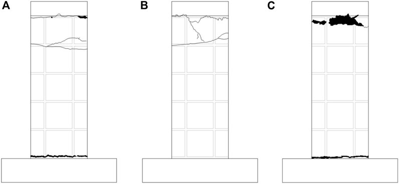
Figure 6. Crack diagram of double-ribbed specimens: (A) specimen DW-20; (B) specimen DW -30; (C) specimen DW -50.
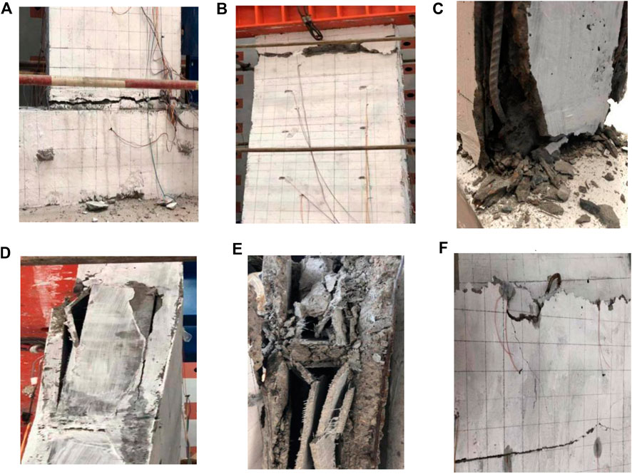
Figure 7. Failure characteristics of double-ribbed specimens: (A) fracture at the joint between the wallboard and the ground beam; (B) fracture at the joint between the loading beam and the wallboard; (C) longitudinal reinforcement bending; (D) peeling off of the concrete surface layer from the core mold; (E) crushing of the core mold; (F) spalling of the concrete.
3.2 Specimen TW-20, TW-30 and TW-50
The three specimens showed no significant changes at the beginning of loading, and the load displacements increased in a positive correlation. Continuing loading, non-structural transverse cracks appeared on the wallboard of all three specimens. As the loading increased, the transverse cracks developed and extended unduly until they penetrated the wallboards. Specimen TW -20 was loaded to 750 kN with severe torsional damage due to fabrication errors and initial twisting of the wallboard that affected the load-bearing capacity of the specimen. When loaded to 800kN, a transverse crack appeared in the middle of the wall panel of specimen TW -30, with a crack length of about 1 m. When loaded to 900 kN, a transverse crack appeared at about 60 cm below specimen TW-30 loading beam, with a length of about 60 cm. When loaded to 1000 kN, two vertical cracks appeared at the corner and mid-span of the specimen TW-30, with a length of about 40 cm. The cracks tended to develop upwards, and the cracks at the back of the wall were symmetrical to those at the front. When loaded to 1150 kN, two vertical cracks were generated at the connection between specimen TW-30 loading beam and the wallboard, and the length of the cracks was about 20 cm.
When loaded to 1250 kN, the core mold inside specimen TW-30 wallboard was crushed. When loaded to 1351 kN, the specimen TW-30 was destroyed. When loaded to 1400 kN, a crack across the wallboard appeared in the middle of the specimen TW-50. When loaded to 1600 kN, vertical cracks appeared in the corner and middle of the panel of the specimen TW-50. When loaded to 1800 kN, the vertical cracks on the ground beam continued to expand above the slope. The vertical cracks on both sides of the wallboard continued to develop upward and widen. Since the multi-channel electro-hydraulic servo loading system has a range of 2000 kN, the test was terminated when loaded to 1975 kN, so the final failure mode was not observed. According to the strain analysis later, it can be speculated that it is close to the failure load. The cracks of the specimen are shown in Figure 8. The overall failure characteristics of the test are as follows: 1) Fracture at the joint between the wallboard and the ground beam, 2) Peeling of concrete from the core mold on the lower sides, 3) Crushing of the core mold, 4) Spalling of the concrete, as shown in Figure 9.
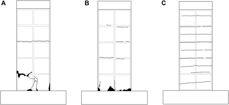
Figure 8. Crack diagram of three-ribbed specimens: (A) specimen TW -20; (B) specimen TW -30; (C) specimen TW -50.

Figure 9. Failure characteristics of three-ribbed specimens: (A) fracture at the joint between the wallboard and the ground beam; (B) peeling of concrete from the core mold on the lower sides; (C) crushing of the core mold; (D) spalling of the concrete.
The experimental phenomena of the double-ribbed and three-ribbed specimens were relatively similar during the test. Most cracks produced were transverse due to the high wall panel height-to-thickness ratio. Various contingent factors resulted in significant additional moments and corresponding lateral deflections. The positions of concrete and core mold stripping for the double-ribbed specimens were mainly on the upper sides of the wallboard. However, most of the three-ribbed specimens were peeled off from the concrete and the core mold on both sides of the lower part of the wallboard. The reason is that the ribs on both sides of the three-ribbed specimen have a specific constraint effect on the panel, which hinders the peeling of the panel and the core mold. Except for specimen TW-20, which was severely torsionally damaged due to fabrication errors, the ultimate load-bearing capacity of the double-ribbed specimen was lower than that of the three-ribbed specimen for the same thickness of the concrete surface layer. Meanwhile, the thicker the concrete surface layer, the greater the ultimate bearing capacity.
4 Analysis of test results
4.1 Axial pressure-displacement curve
The axial pressure-vertical displacement curves of the specimens were obtained from the test data, as shown in Figure 10. The displacements were taken from the average values of axial displacements of displacement gauges D6 and D7. The specimen TW-20 was not involved in the comparison because of the severe torsion damage caused by the production error, which affected the bearing capacity of the specimen. It can be seen from Figure 8 that the vertical displacement increases with the increase of load. Before the peak load, the curve is linear as a whole; the curve of the two-ribbed specimen is bifurcated, and the curve of the three-ribbed specimen is monofurcated. The stiffness of the three-ribbed specimen is higher than that of the double-ribbed specimen. Table 4 is the comparison table of the axial compression bearing capacity of each specimen. It can be obtained from the table that the cracking load of the specimen is 52.99%–60% of the failure load. The double-ribbed specimen cracks earlier than the three-ribbed specimen. Comparing the ultimate bearing capacity of the specimens with the same number of ribs, the ultimate bearing capacity of the specimens increased with the increase of concrete thickness. Specimen DW -30 increased by 4% compared to DW -20, and DW -50 increased by 41.6% compared to DW -30. Under the same concrete surface thickness, the ultimate bearing capacity of the double-ribbed specimen is lower than that of the three-ribbed specimen, indicating that the rib increases the ultimate bearing capacity of the specimen.
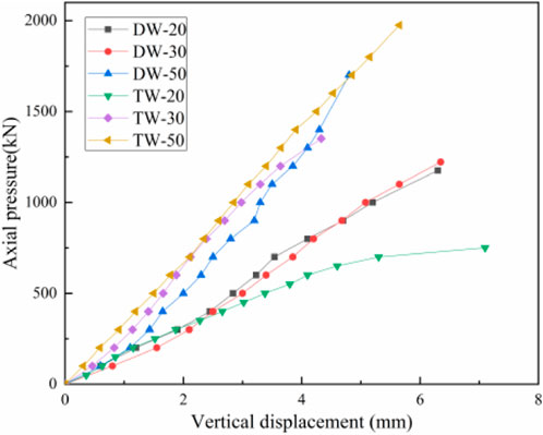
Figure 10. Axial pressure-vertical displacement curve.
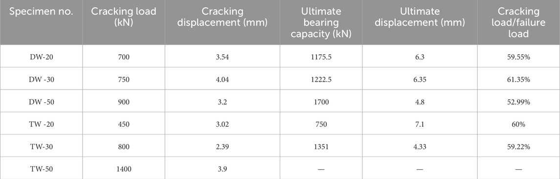
Table 4. Comparison of axial compressive bearing capacity.
The lateral displacement of each specimen was plotted according to the data recorded by displacement gauges D1, D2, D3, D4, and D5. Since the trend is similar for the double-ribbed specimen and the trend is similar for the three-ribbed specimen, take the specimens DW-30 and TW-30 as an example, as shown in Figure 11. The lateral displacement of each measuring point increased with the increase of load. Due to the constraints of loading beams and ground beams at both ends, the lateral displacement in the middle of the wall is too large, and the overall curve is parabolic (Sharda et al., 2021). The asymmetric size of lateral displacements at the upper and lower positions shows more intuitively that the specimens were subjected to different degrees of eccentric loading during the loading process.
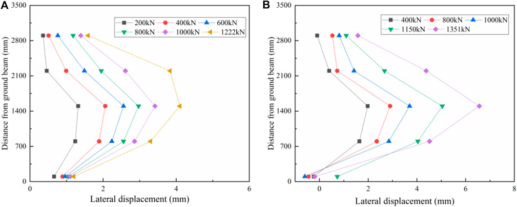
Figure 11. Axial pressure-lateral displacement curve: (A) specimen DW-30; (B) specimen TW -30.
4.2 Axial pressure-strain relationship curve
The concrete strain at each measurement point was collected through the test, and it was found that the trend was similar for the double-ribbed specimens, and the trend was similar for the three-ribbed specimens. Take specimens DW-20, DW-30, and TW-30 as examples to analyze the axial pressure-concrete strain relationship curve, as shown in Figure 12. It can be concluded that the axial pressure of the specimen and the change of concrete strain are linear as a whole, and the concrete strain of each measuring point increases steadily with the increase of load. The development trend of concrete strain at each measuring point of the concrete surface layer was relatively consistent, indicating that each part of the concrete surface layer can be jointly stressed (Xu and Chen, 2022), and the integrity of the specimen was good. Compared with Figures 12A–D, under the same axial pressure, the strain of specimen DW-30 was smaller than that of specimen DW-20. This showed that increasing the thickness of the concrete surface layer of the specimen can reduce the strain, and the thickness of the concrete surface layer had a specific constraint effect on the deformation of the specimen. Compared with Figures 12C–F, the strain of specimen DW-30 at the same height was greater than that of specimen TW-30, indicating that the rib had a certain restraining effect on the deformation of the wallboard. Comparing Figures 12C, D, the ultimate load strains of S10 and S22 of specimen DW-30 were −1431 and −3,709. It can be seen that the specimens were affected by the eccentric compression effect during the loading process, and the local eccentric compression phenomenon was evident. Eccentric compression in different degrees affected the rest of the specimens. Combined with the analysis of the failure mode of each specimen, the position where the strain develops rapidly usually had priority to failure. In the failure stage, different degrees of concrete peeling occurred in the area, causing considerable concrete strain when the specimen was destroyed.
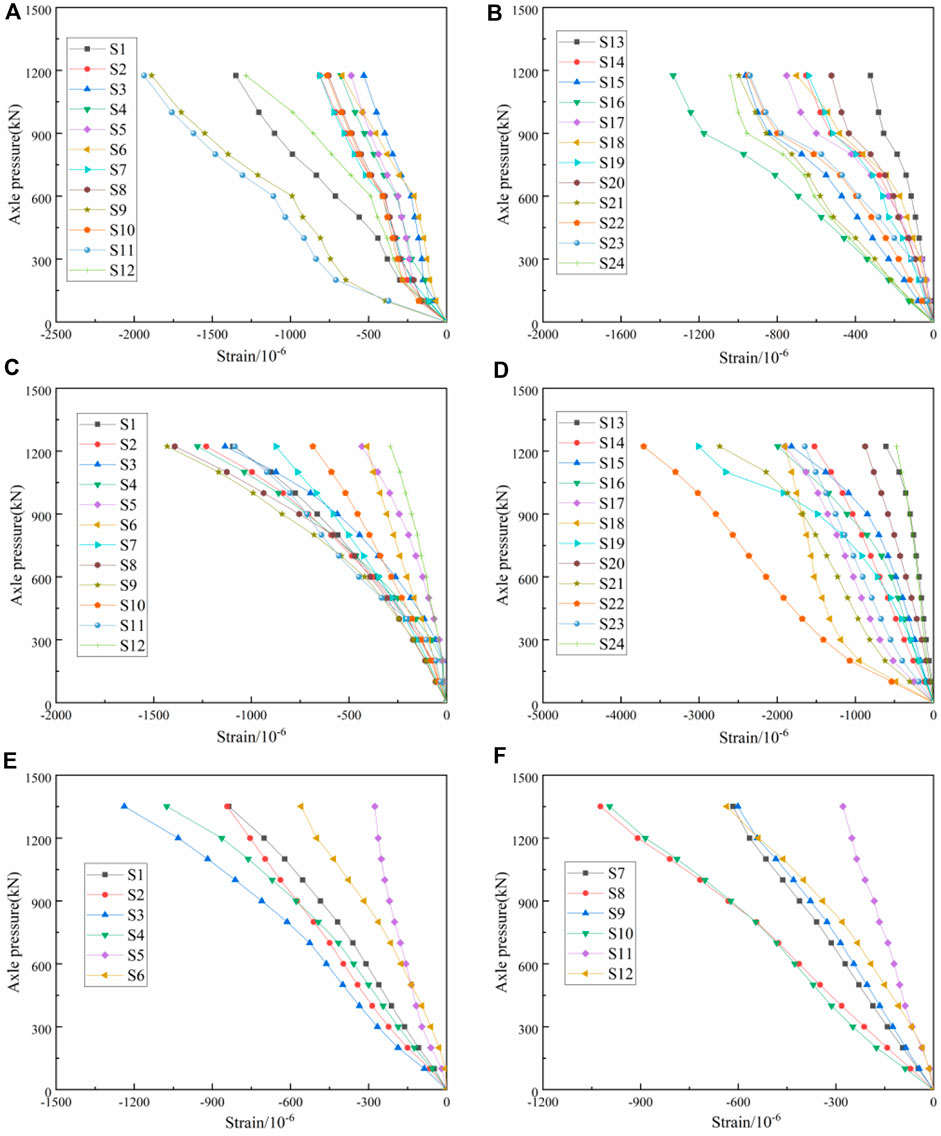
Figure 12. Axial pressure-concrete strain curve: (A) specimen DW-20 front side; (B) specimen DW-20 backside; (C) specimen DW-30 front side; (D) specimen DW-30 backside; (E) specimen DW-30 front side; (F) specimen DW-30 backside.
The steel bars strain of each measuring point was collected through the test, and it was found that the trend of the double-ribbed specimens was similar, as was the trend of the three-ribbed specimens. The axial pressure-rebar strain curves were analyzed by specimens DW-30 and TW-30, as shown in Figure 13. It can be seen from the figure that the strain changes of the steel bars at each height are relatively uniform, indicating that the steel bars can work together in the wallboard and transfer the load together. Under the action of loads at all levels, the larger strain values appeared in the middle of the wall. Combined with the lateral displacement when the specimen was destroyed, the lateral displacement in the middle was more significant, indicating that the specimen was eccentric compression (Palermo et al., 2014; Zhang et al., 2021). The concrete strain in the larger area of the steel bar strain value was also more significant, which reflects that the vertical steel bar can cooperate with the concrete to deform together, and the wallboard had good integrity.
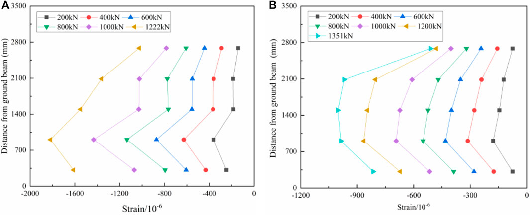
Figure 13. Axial pressure-steel strain curve: (A) specimen DW-30; (B) specimen TW -30.
5 Calculation method of axial compression bearing capacity
5.1 Theoretical calculation of axial compression
Theoretical calculations of compressive bearing capacity of lattice-type wallboard are performed according to the “Code for Design of Concrete Structures” (GB 50010, 2010): Calculated as shown in Equation 1.
Where:
5.2 Consideration of eccentric compression
According to the analysis of the test results, it can be seen that the lattice wallboard was subjected to a certain degree of eccentric compression during the test. Some specimens are greatly affected by eccentric compression, and their compressive bearing capacity should also consider the influence of eccentric compression. Considering the influence of eccentric compression, the following assumptions are made first:
1) The component satisfies the plane section assumption during the loading process; 2) The ultimate failure of the component is caused by the crushing of the concrete at the edge of the component panel; 3) There is an initial eccentricity ea before the member is subjected to axial compression; and 4) The reinforcing steel in the wallboard can be equated to the concrete involved in the distribution of stresses during the calculations.
When performing stress analysis of flexural and axial compression sections, the reinforcement can be calculated by equating it to concrete. The stress analysis of the crushed concrete is carried out through the principle of stress superposition (Guo, 2013), and the analysis sketch is shown in Figure 14.

Figure 14. Calculation diagram.
Where
Equation 5 can be introduced according to Equations 1–4:
Where:
5.3 Calculation and analysis
The theoretical ultimate bearing capacity of the specimen is calculated using the above two methods, and the calculation results are shown in Table 5. The specimen TW-20 was not compared because of the serious torsional damage caused by the production errors. Comparing the calculation results of the axial compression theory with those of the theory considering the eccentric compression, it is found that the values calculated considering the eccentric compression are closer to the test values, so the latter calculation method has better accuracy (Peiris and Mahendran, 2022).
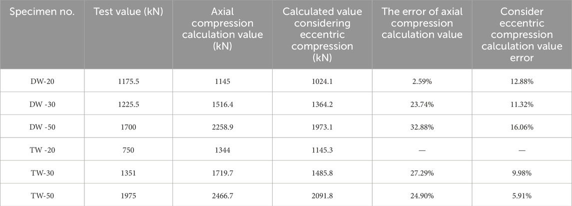
Table 5. Comparison of calculated and tested values of axial compression bearing capacity of specimens.
6 Conclusion
The wallboard’s damage mode, axial pressure-displacement relationship curve, axial compressive bearing capacity, and axial pressure-strain relationship were obtained by axial compression test of six pieces of foot-size new lattice-type wallboard. The effects of concrete face thickness and rib number on the performance of the wallboard were investigated, and the theoretical calculation formula considering eccentric compression was proposed. The main conclusions are as follows:
(1) The test phenomena of the specimens during the test were relatively similar, and most of the cracks produced were transverse cracks. The location of concrete and core mold stripping in double-ribbed specimens was mainly on the upper sides of the wallboard. The three-ribbed specimens were mostly peeled off from the core mold on the lower sides of the wallboard.
(2) Comparing the ultimate bearing capacity of the specimens with the same number of ribs, the ultimate bearing capacity of the specimens increases with the increase of concrete thickness. The ultimate bearing capacity of the double-ribbed specimen was lower than that of the three-ribbed specimen for the same thickness of the concrete surface layer, indicating that the ribs contributed to the bearing capacity of the wallboard.
(3) The strain trend of concrete at each measuring point of the double-ribbed specimen was similar, and the strain trend of concrete at each measuring point of the three-ribbed specimen was also similar. Increasing the thickness of the concrete surface layer of the specimen can reduce the concrete strain, indicating that the thickness of the concrete surface layer has a specific restraining effect on the deformation of the specimen. The concrete strain of the double-ribbed specimen is greater than that of the three-ribbed specimen, indicating that the rib has a specific constraint effect on the deformation of the wall plate. The specimen is affected by eccentric compression during the loading process, and the local eccentric compression phenomenon is evident.
(4) A calculation method for lattice wallboards that considers eccentric compression influence is proposed. Compared with the axial compression calculation method, the calculated value considering the influence of eccentric compression is more consistent with the actual value of the test, which provides a reference for the actual engineering calculation.
Data availability statement
The raw data supporting the conclusions of this article will be made available by the authors, without undue reservation.
Author contributions
YL: Conceptualization, Writing–review and editing. SH: Methodology, Writing–original draft. ZW: Project administration, Resources, Writing–review and editing. DY: Data curation, Investigation, Writing–original draft. KR: Formal Analysis, Investigation, Writing–original draft. JL: Supervision. RW: Validation, Writing–review and editing.
Funding
The author(s) declare that financial support was received for the research, authorship, and/or publication of this article. This research was funded by Anhui Provincial Teaching Research Project, grant number 2020jyxm0347; Anhui Institute of Building Research & Design, grant number AHZPY20201KF; and Anhui Jianzhu University Ph. D Foundation, grant number 2019QDZ29.
Acknowledgments
The authors would like to thank JF of Anhui Jianzhu University for her guidance and advice in revising this article.
Conflict of interest
Author ZW was employed by Anhui Construction Engineering Testing Technology Group Co., Ltd.
The remaining authors declare that the research was conducted in the absence of any commercial or financial relationships that could be construed as a potential conflict of interest.
Publisher’s note
All claims expressed in this article are solely those of the authors and do not necessarily represent those of their affiliated organizations, or those of the publisher, the editors and the reviewers. Any product that may be evaluated in this article, or claim that may be made by its manufacturer, is not guaranteed or endorsed by the publisher.
References
Accornero, F., Cafarelli, R., and Carpinteri, A. (2021). Cracking and crushing in prestressed concrete beams. ACI Struct. J. 118, 101–109. doi:10.14359/51728184
Accornero, F., Cafarelli, R., and Carpinteri, A. (2022). The cohesive/overlapping crack model for plain and RC beams: scale effects on cracking and crushing failures. Mag. Concr. Res. 74, 433–450. doi:10.1680/jmacr.20.00260
Benayoune, A., Samad, A. A., Ali, A. A., and Trikha, D. N. (2007). Response of pre-cast reinforced composite sandwich panels to axial loading. Constr. Build. Mater. 21, 677–685. doi:10.1016/j.conbuildmat.2005.12.011
Bikçe, M., Emsen, E., Erdem, M. M., and Bayrak, O. F. (2021). An investigation on behavior of RC frames with non-interacting infill wall. Eng. Struct. 245, 112920. doi:10.1016/j.engstruct.2021.112920
Borsaikia, A. C., Dutta, A., and Deb, S. K. (2021). Evaluation of participation of masonry infill walls in the linear and nonlinear behaviour of RC buildings with open ground storey. J. Build. Eng. 44, 103263. doi:10.1016/j.jobe.2021.103263
Cao, Q. K., Zhang, J. X., Yang, S. G., Bao, Y. Y., and Xie, R. (2018). Experimental study on axial compression of EPSC latticed concrete wall. Concrete 10, 28–32.
Carpinteri, A., Accornero, F., and Cafarelli, R. (2022). Scale effects in prestressed concrete structures: maximum reinforcement percentage to avoid brittle crushing. Eng. Struct. 255, 113911. doi:10.1016/j.engstruct.2022.113911
Chen, J., Peng, C., Li, C., Ye, X. A., and Wang, Y. (2022). A review of development situation and assessment standard for prefabricated buildings. Build. Struct. 52, 1503–1508. doi:10.19701/j.jzjg.22S2589
Del Zoppo, M., Wijesundara, K., Rossetto, T., Dias, P., Baiguera, M., Di Ludovico, M., et al. (2021). Influence of exterior infill walls on the performance of RC frames under tsunami loads: case study of school buildings in Sri Lanka. Eng. Struct. 234, 111920. doi:10.1016/j.engstruct.2021.111920
Donà, M., Minotto, M., Verlato, N., and da Porto, F. (2022). A new macro-model to analyse the combined in-plane/out-of-plane behaviour of unreinforced and strengthened infill walls. Eng. Struct. 250, 113487. doi:10.1016/j.engstruct.2021.113487
Dong, J., and Fan, L. (2019). Experimental research on mechanical properties of precast light concrete wallboard under axial compression. Ind. Constr. 49, 86–91. doi:10.13204/j.gyjz201903016
Furtado, A., Rodrigues, H., and Arêde, A. (2021). Experimental and numerical assessment of confined infill walls with openings and textile-reinforced mortar. Soil Dyn. Earthq. Eng. 151, 106960. doi:10.1016/j.soildyn.2021.106960
Gallina, G. (2023) “Scale-dependent maximum reinforcement percentage in GFRP-RC beams,” in A fracture mechanics application. Politecnico di Torino.
GB 50010-2010; Code for design of concrete structures. Architecture and Building Press: Beijing, China, 2010.
GB/T 228.1-2010 (2010). Metallic materials - tensile testing - Part 1: method of test at Room temperature. Beijing, China: Standards Press of China.
GB/T50152-2012 (2012). Standard for test method of concrete structures. Beijing, China: Architecture and Building Press.
Goh, W. I., Mohamad, N., Abdullah, R., and Samad, A. A. A. (2016). Finite element analysis of precast lightweight foamed concrete sandwich panel subjected to axial compression. Comput. Sci. Comput. Math. 6, 1–9. doi:10.20967/jcscm.2016.01.001
Grazzini, A., Accornero, F., Lacidogna, G., and Valente, S. (2020). Acoustic emission and numerical analysis of the delamination process in repair plasters applied to historical walls. Constr. Build. Mater. 236, 117798. doi:10.1016/j.conbuildmat.2019.117798
Guo, D., Wang, H. P., Liu, Y. L., Gao, W. Y., and Dai, J. G. (2023a). Structural behavior of CFRP-strengthened steel beams at different service temperatures: Experimental study and FE modeling. Struct. Eng. 293, 116646. doi:10.1016/j.engstruct.2023.116646
Guo, D., Gao, W. Y., Liu, Y. L., and Dai, J. G. (2023b). Intermediate crack-induced debonding in CFRP-retrofitted notched steel beams at different service temperatures: Experimental test and finite element modeling. Compos. Struct. 304, 116388. doi:10.1016/j.compstruct.2022.116388
Hou, L. B., Qian, X., Huo, P., Miao, Q. S., Chen, X., and Huang, L. (2023). Hybrid test of precast concrete frame structures with energy dissipation cladding panels. J. Vib. Shock 42, 276–285. doi:10.13465/j.cnki.jvs.2023.18.031
Jalaeefar, A., and Zargar, A. (2020). Effect of infill walls on behavior of reinforced concrete special moment frames under seismic sequences. Structures 28, 766–773. doi:10.1016/j.istruc.2020.09.029
Jayaprakash, J., Samad, A. A. A., Abbasovich, A. A., and Ali, A. A. A. (2008). Shear capacity of precracked and non-precracked reinforced concrete shear beams with externally bonded bi-directional CFRP strips. Constr. Build. Mater. 22, 1148–1165. doi:10.1016/j.conbuildmat.2007.02.008
Liu, Y. L., Liu, C., Qian, L. P., Wang, A. G., Sun, D. S., and Guo, D. (2023a). Foaming processes and properties of geopolymer foam concrete: Effect of the activator. Constr. Build. Mater. 391, 131830. doi:10.1016/j.conbuildmat.2023.131830
Liu, Y. L., Li, C. F., Zhai, H. X., Ahmad, M. R., Guo, D., and Dai, J. G. (2023b). Production and performance of CO2 modified foam concrete. Constr. Build. Mater. 389, 131671. doi:10.1016/j.conbuildmat.2023.131671
Liu, Y. L., Hao, B. J., Wang, Z. H., Huang, X., Wang, D. H., and Kang, X. (2022). Research on compressive bearing capacity of prefabricated ultra-high performance composite sandwich wallboard. J. West Anhui Univ. 38, 96–104.
Lu, M., and Xue, C. X. (2013). Mechanical performance analysis of lattice of foam concrete energy saving wall. Sichuan Build. Sci. 39, 60–65.
Luo, Y. C. (2008). Research on compression-resisting behaviors of energy-saving block and invisible multi-ribbed frame structure wall. Quanzhou, China: Huaqiao University.
Mo, J., Uy, B., Li, D., Thai, H. T., and Wang, Y. (2022). Behaviour and design of composite walls under axial compression. J. Constr. Steel Research199 199, 107635. doi:10.1016/j.jcsr.2022.107635
Mohamad, N., Goh, W. I., Abdullah, R., Samad, A. A. A., Mendis, P., and Sofi, M. (2017). Structural performance of FCS wall subjected to axial load. Constr. Build. Mater. 134, 185–198. doi:10.1016/j.conbuildmat.2016.12.133
Mohamad, N., Omar, W., and Abdullah, R. (2012). Structural behaviour of precast lightweight foamed concrete sandwich panel as a load bearing wall. Int. J. Sustain. Dev. 5, 49–58.
Palermo, M., Gil-Martin, L. M., Hernandez-Montes, E., and Aschheim, M. (2014). Refined compression field theory for plastered straw bale walls. Constr. Build. Mater. 58, 101–110. doi:10.1016/j.conbuildmat.2014.02.004
Peiris, M., and Mahendran, M. (2022). Advanced numerical modelling of light-gauge steel framed walls subject to eccentric compression. Eng. Struct. 256, 114063. doi:10.1016/j.engstruct.2022.114063
Sharda, A., Manalo, A., Ferdous, W., Bai, Y., Nicol, L., Mohammed, A., et al. (2021). Axial compression behaviour of all-composite modular wall system. Compos. Struct. 268, 113986. doi:10.1016/j.compstruct.2021.113986
Su, R. K. L., and Wong, S. M. (2007). Seismic behaviour of slender reinforced concrete shear walls under high axial load ratio. Eng. Struct. 29, 1957–1965. doi:10.1016/j.engstruct.2006.10.020
Wang, J. F., Zhang, R., Wang, W. Q., Liu, C., Zhang, H. J., and Wang, C. (2021). Experiments and calculation methods on performance of prefabricated cold-formed steel (CFC) composite walls filled with light mortar under axial compression. Ind. Constr. 51, 99–105. doi:10.13204/j.gyjzG20072110
Wang, W., Wang, J., Zhao, P., Ja, L., and Pan, G. (2020). Axial compressive experiments and structural behaviour estimation of CFS composite walls sprayed with LPM. J. Build. Eng. 30, 101305. doi:10.1016/j.jobe.2020.101305
Xu, Y. Y., and Chen, B. Q. (2022). Compression behavior of BFRP grid reinforced geopolymer concrete sandwich insulation wall. J. Central South Univ. ( Sci. Technol. ) 53, 2680–2693.
Yang, K. D. (2021). Study on seismic behavior of cold-formed thin-walled steel plate shear wall. Chongqing, China: Chongqing University.
Zhang, X., Zhang, E., and Li, C. (2021). Study on axial compression mechanical behavior of cold-formed thin-walled C-shaped steel composite wall sheathed with straw board on both sides. Structures 33, 3746–3756. doi:10.1016/j.istruc.2021.06.071
Zhang, X. M., Zhang, X. Y., Liu, W. T., Zhang, X. W., Ding, W. L., and Li, S. (2017). Seismic and axial compression performance of insulated concrete sandwich wall. Proc. Institution Civ. Engineers-Structures Build. 176, 529–543. doi:10.1680/jstbu.20.00212
Keywords: lattice wallboard, axial compression test, axial compression performance, influence of eccentric compression, bearing capacity
Citation: Liu Y, Huo S, Wu Z, Yang D, Ren K, Liu J and Wang R (2024) Research on axial compression performance test and bearing capacity calculation method of newly assembled hollow lattice wallboard. Front. Mater. 11:1424911. doi: 10.3389/fmats.2024.1424911
Received: 28 April 2024; Accepted: 27 June 2024;
Published: 08 August 2024.
Edited by:
Jie Xu, Tianjin University, ChinaCopyright © 2024 Liu, Huo, Wu, Yang, Ren, Liu and Wang. This is an open-access article distributed under the terms of the Creative Commons Attribution License (CC BY). The use, distribution or reproduction in other forums is permitted, provided the original author(s) and the copyright owner(s) are credited and that the original publication in this journal is cited, in accordance with accepted academic practice. No use, distribution or reproduction is permitted which does not comply with these terms.
*Correspondence: Riguang Wang, d3JnMjAwMzEzQGFoanp1LmVkdS5jbg==