 Xue Lei1
 Shengtai Zhou
95% of researchers rate our articles as excellent or good
Learn more about the work of our research integrity team to safeguard the quality of each article we publish.
Find out more
ORIGINAL RESEARCH article
Front. Mater. , 19 June 2024
Sec. Polymeric and Composite Materials
Volume 11 - 2024 | https://doi.org/10.3389/fmats.2024.1415283
This article is part of the Research Topic Injection Molding of Polymeric and Composite Materials View all 6 articles
Microinjection molding (μIM) is an important technique to fabricate microparts for applications in the fields of automotive and microelectromechanical systems. However, the prevailing high shear conditions in μIM are unfavorable for constructing intact electrically conductive networks because the added fillers tend to be preferentially aligned along the melt flow direction. In this work, a series of polypropylene/polyamide 6/carbon black (PP/PA6/CB) composites with a selective localization of CB in the PA6 phase were used as the model system to prepare electrically conductive microparts. The prevailing high shearing and extensional flow effects in μIM were utilized to deform CB-rich phase with an aim to in situ construct electrically conductive network, thereby improving the electrical conductivity (σ) of subsequent moldings. The results indicated that a higher σ was achieved for PP/PA6/CB microparts when compared with their PP/CB and PA6/CB counterparts, at a lower filler content (<10 wt%). The influence of blending sequence of various components (i.e., PP, PA6, and CB) and annealing treatment on the σ of microparts was also studied. This work provided an approach to the design and preparation of electrically conductive microparts that can be potentially used in high-tech sectors.
With the development of microelectromechanical systems, a substantial market has emerged for lightweight polymeric micro-components (Cao et al., 2013; Zhou et al., 2016; Zhou et al., 2017b; Nazemi et al., 2019; Zhu et al., 2019). Microinjection molding (μIM) has been geared for fabricating polymeric micro devices (Huang and Chiu, 2005; Giboz et al., 2007; Agour et al., 2016; Zhang et al., 2022). The products are characterized by an overall part weight less than several milligrams or dimension featuring at micron-scales (Whiteside et al., 2004). Thus, polymer melts experience a significant cooling effect when they come into contact with the mold cavities. Consequently, very high injection velocities and injection pressures as well as elevated temperatures are required to ensure a complete filling (Shi et al., 2019; Zhang et al., 2022), thereby leading to a significant shearing and thermal gradients within the microparts (Ameli et al., 2017).
It has been reported that the degree of orientation and disentanglement of multiwalled carbon nanotubes (MWCNTs) was increased with increasing shear rates (Pujari et al., 2009). In μIM, the prevailing shear rate as high as 105 s−1 are common which would thus lead to a significant orientation of fillers in related moldings (Zhou et al., 2016). Fernandez-Ballester et al. (2012) reported that a difference in the morphology of crystals formed in the skin and core layer was observed when polypropylene (PP) was exposed to a significant flow effect. Zhou et al. (2017a) reported that the compression molded PP/carbon composites demonstrated higher electrical conductivity (σ) and lower percolation threshold when compared with corresponding micromoldings. Under such circumstances, the prevailing high shear rates in μIM are considered unfavorable for the construction of intact filler network because fillers were subjected to strong shearing and extensional flow effects along the flow direction and impaired the formation of three-dimensional filler network. Therefore, it becomes necessary to explore new strategies to improve the σ of microparts which meet the standards for high performance engineering sectors.
Various strategies (Naficy and Garmabi, 2007; Deng et al., 2014; Zhou et al., 2017a; Salehiyan and Ray, 2018; Zhao et al., 2021) such as the use of high efficiency conductive fillers and controlling the morphology of the composites are adopted to reduce the percolation threshold of conductive polymer composites (CPCs). Regulating the morphology of immiscible blends (i.e., materials with at least two phases) and the selective localization of fillers in one particular phase or at the interface of two phases are critical for preparing CPCs with high σ (Shen et al., 2017; Zhang et al., 2019a; Zhang et al., 2019b; Hosseinpour et al., 2019). The distribution of fillers in the immiscible blend is affected by both thermodynamic and kinetic factors (Baudouin et al., 2010; Taguet et al., 2014; Hoseini et al., 2017b). From the thermodynamic perspective, the wetting coefficient (ωa) is generally adopted to estimate the distribution of fillers in the host blends. The calculation of ωa is displayed in Eq. 1.
Here, f means filler and p means polymer phase; γx,y is the interfacial tension between x and y. When ωa < −1, fillers are located in polymer 1 (i.e., p1); when ωa > 1, fillers tend to be located in polymer 2 (p2); when −1<ωa < 1, the fillers are distributed at the phase interface (Sumita et al., 1991; Pan et al., 2016). The above shows that the interfacial interaction is a dominant factor that determines the distribution of fillers in the host substrate. Gültner et al. (2011) found that the distribution of MWCNTs could be tuned in polycarbonate/poly(styrene-co-acrylonitrile)/MWCNT (PC/SAN/MWCNT) composite by adding reactive component that had better affinity for SAN phase. The chemical reaction or strong interaction was believed to be the driving force that facilitated the migration of MWCNTs from the PC phase to SAN phase. Moreover, the kinetic factors such as the blending sequence, blending time, and shear rate also affected the distribution of conductive fillers. Zhou et al. (2021) found that by controlling the blending sequence and time, the distribution of CNTs could be mitigated to the interface of polystyrene (PS) and poly(methyl methacrylate) (PMMA) (50/50) blends, thereby resulting in a great increase of σ and dielectric constant at a filler concentration of 1.06 vol%. Furthermore, the creation of micro fibrillar structure was also adopted by researchers to reduce the percolation threshold of CPCs. Yu et al. (2013) prepared PP/polyethylene (PE)/CNTs composites by thin-wall injection molding process, and a typical continuous layered structure consisting of alternating PE/CNT and PP layers was formed within the molded samples, which was important for achieving the electromagnetic interference (EMI) shielding performance when compared with the composites with isotropic conductive networks.
In the present study, polymer composites with oriented conductive filler network structure were realized by the shear- and extensional flow induced deformation and coalescence of filler-rich phase in immiscible composites. To achieve this goal, PP/polyamide 6 (PP/PA6) blend was adopted as the model system and carbon black (CB) was used as the conductive filler. Generally, CB has a tendency to distribute within PA6 due to the higher affinity of fillers for the polar matrix. The CB-rich PA6 phase was likely deformed under the influence of high shearing conditions in μIM (Zhou et al., 2018a), and the deformed PA6/CB phase would thus form continuous CB network along the flow direction, thereby giving rise of σ for subsequent microparts. Furthermore, the effect of blending sequence and annealing treatment on the σ of PP/PA6/CB microparts was systematically conducted to elucidate their influence on the formation of filler network within micromoldings. In summary, this work provided an example to utilize the high shearing effects that are normally considered detrimental to construct conductive filler network in injection molded samples, and prepare a series of electrically conductive microparts which show promising application in automotive, electronics and microsystems among others.
Polypropylene (PP) pellets under the trademark of PPH-T03 were purchased from Sinopec Oil and Chemical Co., Ltd. (China). The material has a melt flow index of 3.0 g/10 min (@ 230°C and 2.16 kg) and a density of 0.91 g/cm³. Polyamide 6 (Trademark: Ultramid® B3S) with a volume flow rate of 160 cm³/10 min (@ 275°C and 5 kg) was supplied by BASF. The material has a density of 1.13 g/cm3. High structure carbon black (CB) under the trademark of Ketjenblack®EC-600JD was supplied by Akzo Nobel Polymer Chemicals LLC (Chicago, IL). The highly branched CB has an electrical resistivity of 0.01–0.1 Ω cm, a density of 1.80 g/cm3, and pore volume of 480–510 cm3/100 g according to literature (Zhou et al., 2017a).
Firstly, a series of PP/CB, PA6/CB and PP/PA6/CB composites with different filler content (i.e., 1, 2, 3, 4, 5, 7, 10 and 15 wt%) were fabricated by melt blending method using a HAAKE POLYLAB OS torque rheometer. Based on a previous work, the mass ratio of PP:PA6 was set at 70:30 and the compounding process was operated at 240°C and 50 rpm for 10 min.
(i) To investigate the influence of filler concentration on the electrical conductivity of PP/PA6/CB composites and microparts, a series of filler concentrations ranging from 1 to 15 wt% were adopted. All components were compounded simultaneously at 240°C and 50 rpm for 10 min.
(ii) To investigate the effect of blending sequence of various components (i.e., PP, PA6 and CB) on the properties of PP/PA6/CB microparts, the content of CB was fixed at 7 wt% because the electrical conductivity of resulting composites and microparts was detectable which would minimize the error for measurements. The following protocols were adopted to prepare composites for molding: 1) PP, PA6 and CB were simultaneously blended in the Brabender mixer for 10 min. The obtained sample was denoted as PP/PA6/CB; 2) PP was firstly blended with CB for 5 min, then PA6 was added and compounded for another 5 min to prepare PP/PA6/CB composites. The sample was named as PP/CB+PA6; 3) PA6 was firstly blended with CB for 5 min, then PP was added and compounded for another 5 min to prepare PP/PA6/CB composites. The sample was named as PA6/CB+PP. The melt temperature was set at 240°C and the screw rotation speed was 50 rpm for the above experiments.
Dumbbell-shaped microparts were prepared using a full electric microinjection molding machine (Model: Micro Power 5, WITTMANN BATTENFELD GmbH, Kottingbrunn, Austria). The melt temperature for preparing PP/CB microparts and PA6/CB microparts were set at 190°C and 240°C, respectively. The mold temperature was 80°C, the injection velocity was 300 mm/s, and the injection pressure was 100 MPa. The micropart has a thickness of 0.3 mm, a width of 2 mm and a length of 20 mm. The schematic diagram of the prepared micropart and the regions for subsequent characterizations were presented in Figure 1. For a comparison purpose, compression molded PP/CB samples were prepared at 190°C and compression molded PP/PA6/CB samples were prepared at 240°C using a hot press (Model: YP-100 D, Shanghai Ximaweili Rubber and Plastic Machinery Limited Company, China). All compression molded samples were prepared under the pressure of 10 MPa for 10 min.
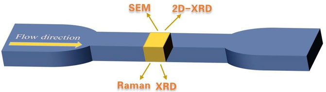
Figure 1. The diagram for the testing regions of Raman, XRD, SEM, and 2D-XRD measurements.
Samples were measured by a high resistance meter (Model: SM7110, Hioki E.E. Corporation, Nagano, Japan). The electrical conductivity (σ) was calculated as per the following equation:
Here, ρ: volume resistivity; R: electrical resistance; L: the length of testing strip; S: the cross-sectional area. The flow direction σ was reported for injection molded samples.
The morphology of the samples was observed using a scanning electron microscope (SEM, Thermoscientific Apreo S, Oxford Instruments, United Kingdom) and a transmission electron microscopy (TEM, Thermofisher, Talos F200S G2, United States).
For SEM observations, samples were cryo-fractured in liquid nitrogen. For the samples which were prepared by adopting different blending procedure, PA6 phase was etched using formic acid for 12 h. All samples were coated with a thin layer of gold prior to observations. A Leica ultramicrotome (EM UC7/FC7) was utilized to cut micropart perpendicular to the flow direction with a slice thickness of 10 nm, then followed by TEM observation.
The rheological measurements were performed on a dynamic rheometer (Model: MCR 302, Anton Paar, Austria). The PP/PA6/CB and PA6/CB composites were tested at 240°C and PP/CB composites were tested at 190°C. The applied strain was set at 1% and the range of frequency sweep ranged from 0.01 to 100 Hz.
Two-dimensional (2D) X-ray diffraction (XRD) analysis was conducted using a D8 DISCOVER diffractometer (Bruker Corporation, Billerica, MA, United States) equipped with a 2D detector (VANTEC-500) with Cu radiation. The XRD patterns were collected within a range of 0°–100° at a step size of 0.01°. XRD scans for each sample were obtained from an X-ray diffractometer (XRD, Ultima IV, Rigaku, Japan) with Cu Kα radiation (K = 0.1542 nm, where K is the wavelength). XRD patterns were collected at room temperature in a range of 2°–90° at a step size of 0.02°.
The tensile strength of samples was measured by a universal mechanical tester (Instron 5569, Instron Corporation, United States) with a crosshead speed of 5 mm/min. Five specimens were tested for each sample to ensure the consistency of the results.
The Raman spectra were collected using a Raman spectrometer with a 532 nm laser and a Raman imaging microscope (DXR3xi, Thermo ScientificTM, United States). The wavelength range is from 50 to 3,400 cm−1.
The values of electrical conductivity (σ) for PP/CB, PA6/CB and PP70/PA630/CB composites as a function of filler concentration were presented in Figure 2. Figure 2A showed that both PP/CB and PP70/PA630/CB 1 wt% composites remained insulative due to the lack of conductive filler network. Notably, the σ of compression molded PP70/PA630/CB 2 wt% composite showed a significant increase when compared with that of PP/CB 2 wt%, which was related to the selective localization of CB in minor PA6 phase. In this scenario, the presence of CB-rich PA6 phase enriched the local “effective filler concentration” and it favored the formation of conductive pathways that contributed to improving the σ of PP70/PA630/CB 2 wt% composite. Moreover, the σ of PP70/PA630/CB 3 wt% composite was comparable to that of PP/CB 3 wt%, suggesting that sufficient conductive pathways were formed by CB within the host matrix. Afterward, the σ of PP70/PA630/CB composites was inferior to that of PP/CB counterparts when the filler content exceeded 3 wt%. Under such circumstances, the following factors were believed responsible for the above observations: 1) for PP70/PA630/CB composites, the possible coating of PA6 matrix surrounding CB particles due to the higher interactions between PA6 and CB likely impaired the formation of intact filler network (Hoseini et al., 2017a); 2) for PP/CB composites, the formation of well crystalline PP phase favored the migration of CB particles to the amorphous region of PP/CB composites (Abbasi et al., 2011). As a result, the enrichment of CB fillers in the amorphous phase led to an increase of σ for PP/CB composites when compared with PP/PA6/CB counterparts.
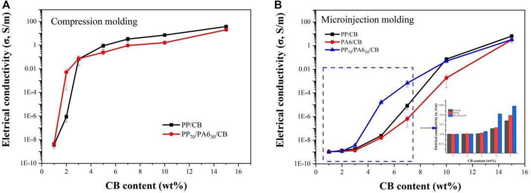
Figure 2. The electrical conductivity of PP/CB, PA6/CB and PP70/PA630/CB composites which were prepared by different methods with different CB concentrations: (A) compression molding; (B) microinjection molding.
The σ for PP/CB, PA6/CB and PP70/PA630/CB microparts as a function of CB concentration were presented in Figure 2B. The results indicated that all samples remained insulative when the concentration of CB was <5 wt%. The above finding suggested that the prevailing higher shearing and extensional flow effects in μIM reduced the probability of forming intact CB network. Moreover, the σ of PP70/PA630/CB microparts was higher than that of PP/CB and PA6/CB counterparts, when the filler concentration was <10 wt%. This also suggested that the preferred distribution of CB in the PA6 phase was favorable for the formation of conductive filler network in the host matrix, thereby giving rise of the σ. In addition, the σ of PP/CB microparts was slightly higher than that of PP70/PA630/CB microparts with further increasing CB content (≥10 wt%). In this scenario, the CB particles had formed sufficient conductive pathways within both samples, and the possible presence of PA6 matrix layer surrounding CB might lead to a reduction of σ, as reflected by the lower σ for PA6/CB 10 wt% micropart when compared with that of PA6/CB and PP70/PA630/CB counterparts.
The microstructure of PP/CB and PP/PA6/CB composites which were prepared by different methods was observed using SEM, as shown in Figures 3, 4, respectively. Figures 3A, B showed that CB was relatively uniformly distributed in PP, provided the presence of some CB agglomerates. Moreover, no filler network was detected at a filler content of 1 wt% and the adjacent distance among CB fillers was substantially reduced when the filler concentration reached 5 wt%, which was critical for improving σ. The morphology of PP70/PA630/CB 1 wt% and PP70/PA630/CB 5 wt% composites were presented in Figures 3C, D. Figure 3C showed that typical sea-island structure was observed in compression molded PP70/PA630/CB 1 wt% sample with the minor PA6 phase as the dispersed phase. In addition, the white dots which denoted the presence of CB fillers were mainly found in the island region and such phenomenon became more obvious with increasing CB concentration (see Figure 3D), which was a result of the better affinity of CB for the PA6 phase (Tanniru and Tambe, 2022). The observed voids on the fractured surface were indicative of the poor interfacial interaction between PP and PA6 phase. Notably, CB-rich PA6 phase became coarser and showed an irregular phase interconnection at 5 wt% CB, and the interconnection among CB-rich phase contributed to enhancing the σ of corresponding moldings (Sultana et al., 2019). The selective localization of CB fillers increased the viscosity of the dispersed PA6 phase and increased the tendency to form co-continuity structure in the immiscible blend owing to the self-networking of CB (Wu et al., 2010), as displayed in Figure 3D.
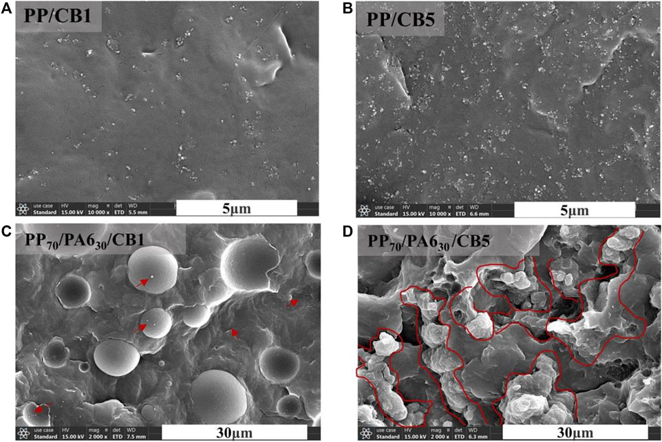
Figure 3. SEM images of compression molded PP/CB and PP70/PA630/CB composites at different filler concentrations: (A) PP/CB 1 wt%; (B) PP/CB 5 wt%; (C) PP70/PA630/CB 1 wt%; (D) PP70/PA630/CB 5 wt%.
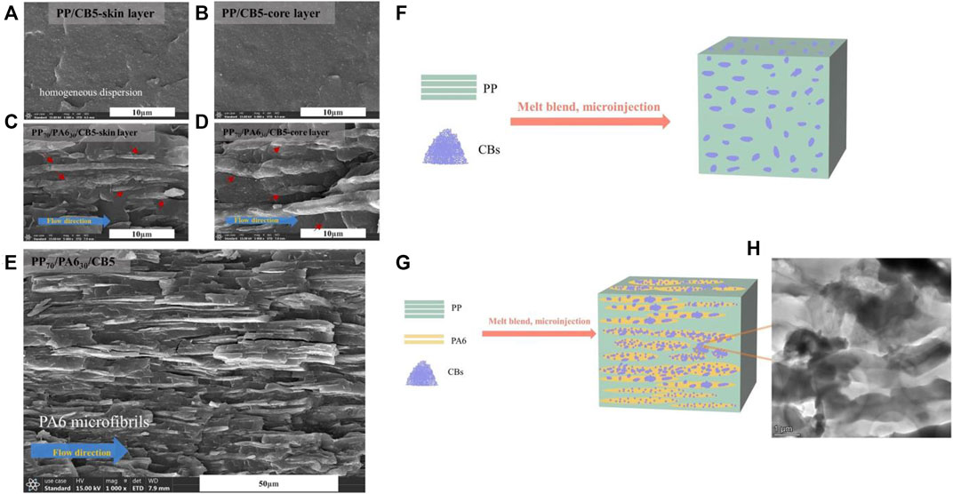
Figure 4. (A–D) SEM images of PP/CB 5 wt% and PP70/PA630/CB 5 wt% microparts which were observed from both shear and core regions. (E) SEM image of PP70/PA630/CB 5 wt% micropart which was etched using formic acid to remove PA6 phase; schematic diagram for the microstructure evolution of (F) PP/CB and (G) PP70/PA630/CB when they were processed using μIM. (H) TEM image of PP70/PA630/CB 5 wt% micropart.
The morphology of PP/CB 5 wt% and PP70/PA630/CB 5 wt% microparts was observed using SEM, as displayed in Figures 4A–D. Figures 4A, B revealed that CB demonstrated improved state of distribution in both the shear and core layer of the microparts, which was attributed to the influence of higher shearing effect that prevailed in μIM which favored the dispersion of nano-particles (Ferreira et al., 2013; Liu et al., 2015). This in turn reduced the probability of generating CB filler network in subsequent microparts, and thus a higher CB concentration was required to construct conductive pathways within PP/CB microparts. The morphology of PP70/PA630/CB 5 wt% micropart which was observed from shear and core layers was exhibited in Figures 4D, E, respectively. Unlike compression molded PP70/PA630/CB 5 wt% composites, the results suggested that the oriented layered phase structure with CB was observed in both shear and core layers of the microparts, indicating that a severe phase deformation and coalescence of CB-rich PA6 phase occurred under the intensive shearing and extensional flow conditions of μIM (Ding et al., 2015; Zhao et al., 2020; Wang et al., 2021) which was advantageous to the improvement of σ.
The microstructure of PP70/PA630/CB 5 wt% micropart which was etched using formic acid to remove PA6 phase was shown in Figure 4E. The observation also corroborated the hypothesis that spherical PA6/CB phase would be deformed to generate interconnected continuous phase structure that resulted in the formation of intact conductive pathways along the flow direction. As a result, the σ of PP70/PA630/CB 5 wt% micropart was approximately 3 orders higher than that of PP/CB and PA6/CB counterparts.
The microstructure evolution of PP/CB and PP70/PA630/CB composites under the processing conditions of μIM was depicted in Figures 4F, G, respectively. It clearly conveyed the idea that CB particles achieved improved distribution in PP/CB microparts which impaired the formation of intact conductive pathways, whereas the selective localization of CB in the PA6 phase and the subsequent phase deformation/coalescence induced by high shearing and high extensional flow effects favored the construction of CB filler network, thereby giving rise of σ for PP70/PA630/CB micropart, as shown in Figure 2B. The microstructure among the interphase of PP and PA6/CB was observed using TEM, as shown in Figure 4H. The result revealed that CB formed intact filler network among the deformed phases, and it suggested that CB fillers would likely migrate towards the interface of PA6 domains when it reached saturation inside the PA6 phase (Zhang et al., 1998), which was also responsible for improving the σ.
The structure evolution of samples which were prepared by CM and μIM was analyzed using 2D XRD and XRD analysis, as exhibited in Figure 5. Figures 5A–D showed that regardless of filler concentration, uniform and circular bright arcs were observed for CM samples whereas such phenomenon was absent from the microparts, signifying the formation of well-developed crystals in compression molded samples due to the lack of strong shearing influence (Ding et al., 2017). The above results suggested that strong shearing and cooling effects in μIM were disadvantageous to the formation of well-developed crystals, albeit there was a shear-induced crystallization of polymer chains. The XRD pattens for both CM and microinjection molded samples were displayed in Figure 5E. The results showed that samples demonstrated nearly similar patterns with the microparts exhibiting distinct β (110) crystal peaks. In addition to β (110) peak, the intensity of XRD peaks for the microparts diminished when compared with the CM samples, suggesting that the high shear and cooling effects in μIM favored the formation of β crystals (Zhao et al., 2015; Chen et al., 2016) whereas they suppressed the formation of the other type crystal forms.
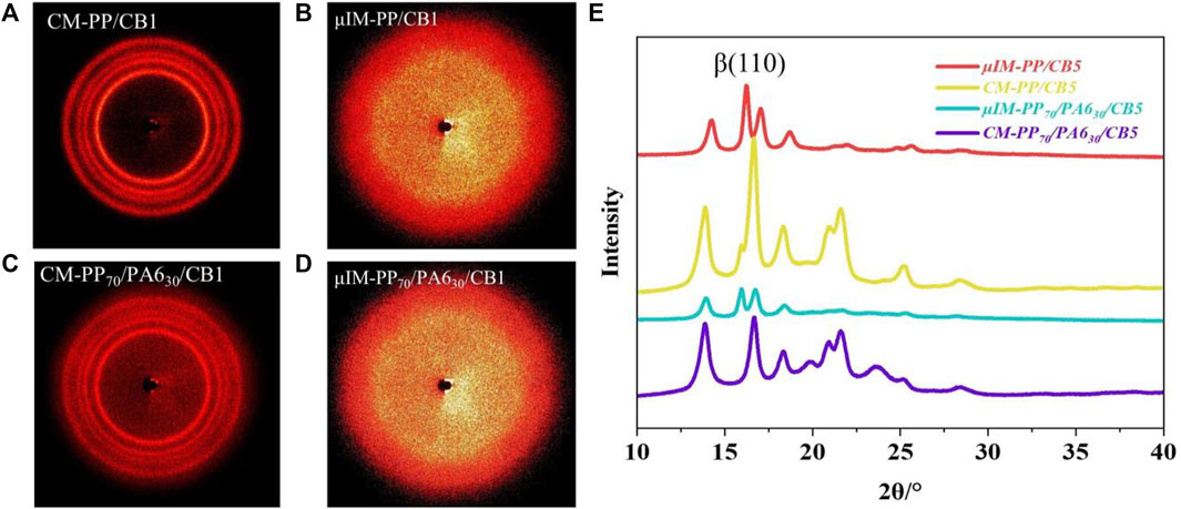
Figure 5. (A–D) 2D-XRD images of PP/CB 1 wt% and PP70/PA630/CB 1 wt% composites which were prepared by CM and μIM; (E) XRD patterns of PP70/PA630/CB 5 wt% and PP/CB 5 wt% composites which were prepared by CM and μIM.
Raman spectral analysis is one of the most useful techniques to characterize the carbon-based fillers and their composites (He et al., 2015; Simoncini et al., 2017; Bokobza, 2019). The characteristic peaks which were detected in the vicinity of 1,360 and 1,580 cm-1 were attributed to the D-band (disorder band) and G-band (graphite band or TM-tangential mode) (Abbasi et al., 2010), respectively. The ratio of peak intensity, i.e., ID/IG was normally used as an indicator to reflect the state of orientation or the perfection of carbon fillers. As depicted in Figure 6, the ID/IG for the microparts was lower than their CM counterparts, suggesting that there was a stronger filler orientation of carbon fillers in the micromolded samples. The above result indicated that the strong shear and extensional flow effects in μIM led to the disintegration of CB agglomerates and the preferably distribution along the flow direction.
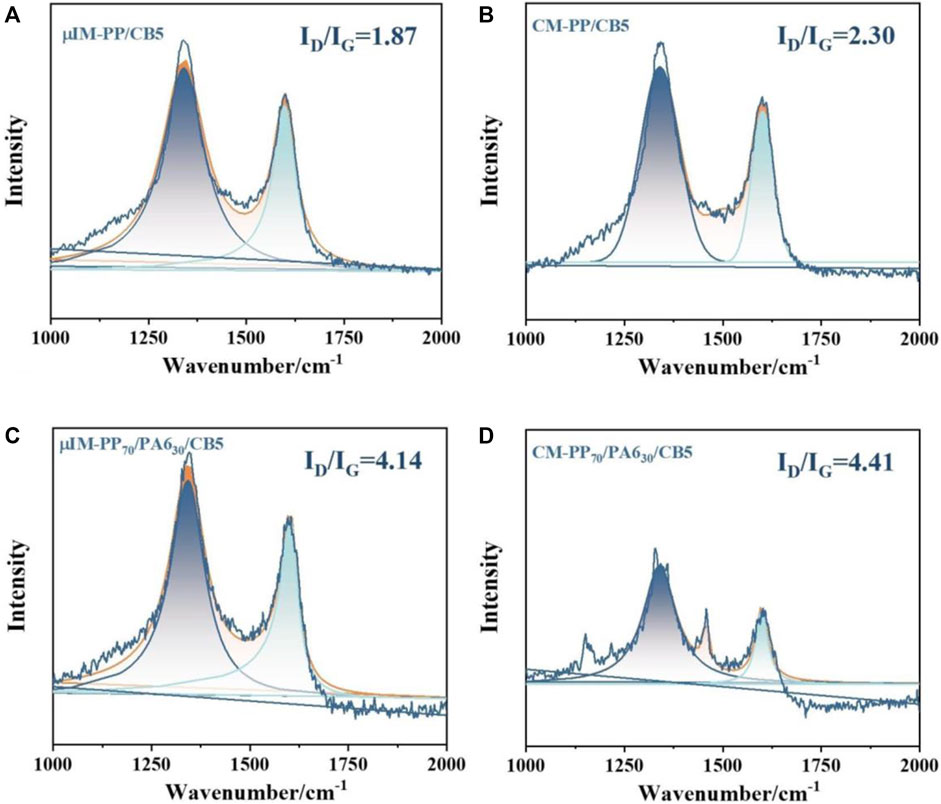
Figure 6. Raman spectral analysis of PP/CB5 and PP70/PA630/CB5 composites which were prepared by CM and μIM: (A) PP/CB 5 wt% micropart; (B) CM PP/CB 5 wt% composite; (C) PP70/PA30/CB 5 wt% micropart; (D) CM PP70/PA30/CB 5 wt% composite.
Rheological analysis is useful for characterizing the percolative structure that formed within the composites (Pötschke et al., 2002). The dependence of storage modulus (G′), loss modulus (G″), and complex viscosity (η*) as a function of frequency for PP/CB and PP70/PA630/CB composites along with corresponding Han curves was presented in Figures 7, 8, respectively. The results clearly showed that both the G′ and G″ increased significantly with the addition of CB, illustrating an enhanced resistance to shear deformation and a transition of viscous liquid to elastic solid due to the formation of CB network. Additionally, Figures 7C, 8C showed that CB-containing composites showed obvious shear-thinning behavior, especially for those with high CB concentrations, further confirming that a transition from the viscous to solid state occurred with increasing filler content and this was related to the formation of filler network by the physical connection among CB particles (Yang et al., 2008; Jaber et al., 2011; Ren et al., 2014).
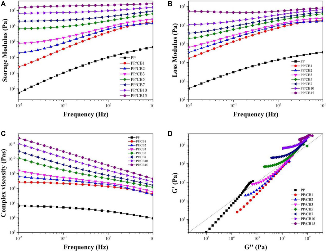
Figure 7. The (A) storage modulus, (B) loss modulus, (C) complex viscosity and (D) Han curves of PP/CB composites.
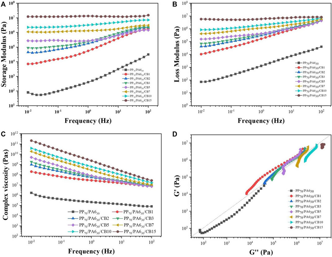
Figure 8. The (A) storage modulus, (B) loss modulus, (C) complex viscosity and (D) Han curves of PP70/PA630/CB composites.
Furthermore, the changes of G′ vs. G″, i.e., Han curves, for PP/CB and PP70/PA630/CB composites were given in Figures 7D, 8D, respectively. Pötschke et al. (2002) proposed that a shift and change in the slope of G′ vs. G″ indicated a change in the microstructure of filler-loaded polymer composites. Figure 7D showed that the Han curves for PP/CB composites deviated greatly when the concentration of CB was in the vicinity of 3 wt%, which was consistent with the significant increase of σ (as shown in Figure 2A). In addition, the Han curves of PP70/PA630/CB 1 wt% composite started to deviate from that of PP70/PA630 blend, suggesting that CB particles were capable of forming filler network at a relatively lower filler content when compared with PP/CB composites. Also, CM PP70/PA630/CB 1 wt% composite showed a significant increase of σ which was related to the formation of filler network. The above results indicated that the rheological percolation threshold coincided with that of electrical percolation threshold, and the use of immiscible PP/PA6 blend as the host matrix increased the efficacy of CB in forming intact filler network that was indispensable for improving σ.
The above results showed that the selective localization of CB particles in the PA6 phase was advantageous to form intact conductive filler network, which was critical for improving the σ. To further investigate the blending sequence of various components (i.e., PP, PA6 and CB) on the evolution of microstructure and properties of corresponding micromoldings, PP and PA6 with a mass ratio of 70:30 and a CB content of 7 wt% was used as the model system. Three blending sequences were employed, as described in Section 2.2.
The σ and tensile strength of PP70/PA630/CB 7 wt% microparts were displayed in Figures 9A, B, respectively. Figure 9A showed that PP/CB+PA6 micropart exhibited the highest σ (4.6 × 10⁻² S/m) among the studied systems, which was 69 times higher than PP/PA6/CB and 2.7 × 10⁶ higher than PA6/CB+PP. In addition, Figure 9B showed that PP/PA6/CB and PP/CB+PA6 microparts showed comparable tensile strength and the tensile strength of PA6/CB+PP was minimum. Such difference in σ and tensile strength for related microparts was related to the microstructure in corresponding moldings.
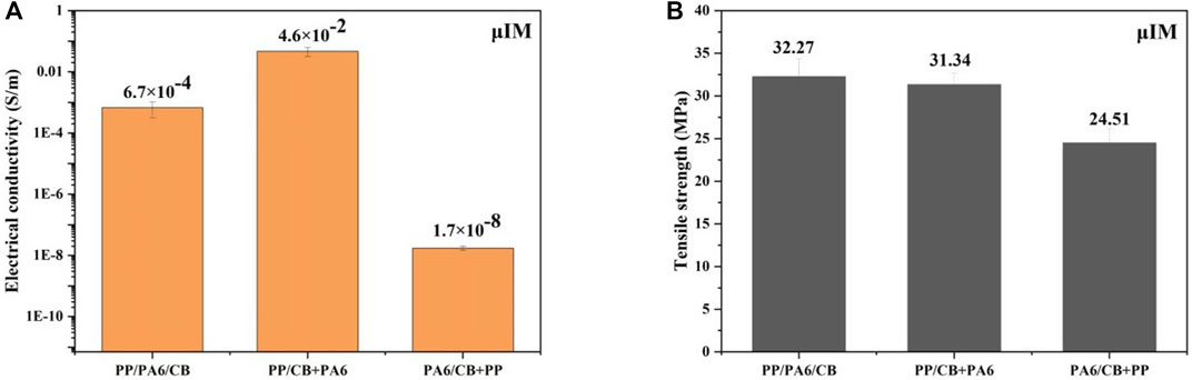
Figure 9. The (A) electrical conductivity and (B) tensile strength of PP70/PA630/CB 7 wt% microparts with different blending sequences.
SEM images of microparts which were molded from PP/PA6/CB composites that prepared using different blending protocols were displayed in Figure 10. Notably, the difference in the microstructure of microparts varied greatly when different processing procedure was adopted to prepare PP/PA6/CNT composites. Figure 10 showed that the dispersed PA6 phase in PP/CB+PA6 was elongated to form fibrillar structure which was beneficial for enhancing the mechanical properties and σ of corresponding moldings (Zhang et al., 2009); in addition, the phase area of PA6 in PP/PA6/CB micropart was larger than that of PP/CB+PA6, whereas the PA6 phase in PA6/CB+PP was unevenly distributed because the selective localization of CB increased the viscosity of CB-rich PA6 phase which would significantly affect the development of microstructure when compared with PP/CB+PA6 and PP/PA6/CB counterparts. Under such circumstances, the premixing of PA6 and CB resulted in an increase of the viscosity of PA6/CB, and the subsequent blending between PA6/CB and PP would be insufficient to yield a uniformly distributed PA6/CB phase in the PP substrate. Afterwards, the deformation and coalescence of PA6/CB phase led to the uneven distribution of CB-rich PA6 phase, which was not advantageous to the simultaneous enhancement of σ and tensile strength when compared with the other samples, as displayed in Figures 9A, B, respectively.
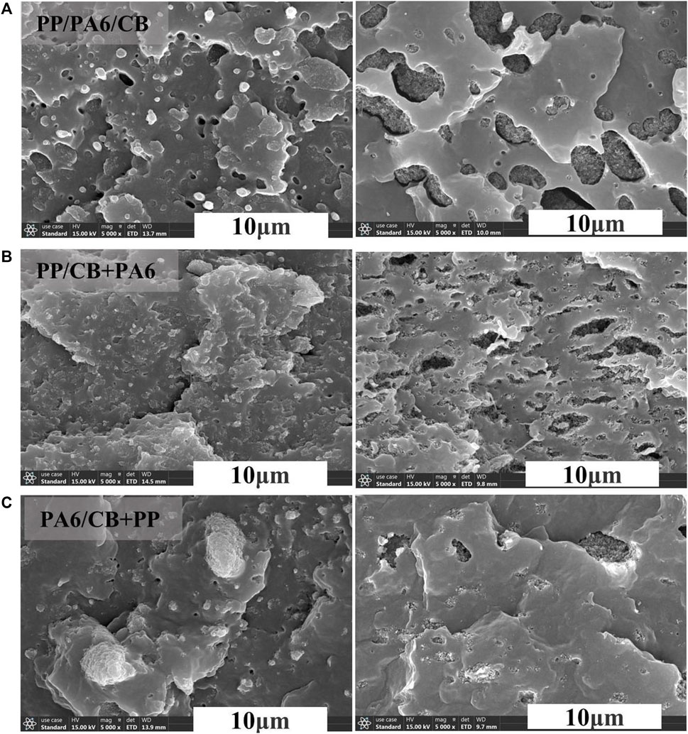
Figure 10. SEM images of PP70/PA630/CB 7 wt% microparts with different blending sequences: (A) PP/PA6/CB; (B) PP/CB+PA6; (C) PA6/CB+PP. Herein, the right column showed the images of samples which were etched using formic acid.
Annealing treatment is considered as an effective approach to improve the performance of polymer composites (Li et al., 2015; Zhou et al., 2018b; Shi et al., 2021). Herein, the above molded samples were annealed at 150°C for 1 h. Afterwards, samples were allowed to cool down to room temperature for σ and tensile tests. The values of σ and tensile strength for ternary PP/PA6/CB microparts before and after annealing were presented in Figures 11A, B, respectively. The results suggested that both the σ and tensile strength of the annealed samples were higher than their unannealed counterparts. Specifically, the σ of annealed PP/CB+PA6 micropart reached as high as 0.106 S/m, which was the optimal among the studied systems. Meanwhile, the tensile strength was increased from 31.3 to 36.9 MPa, which indicated that the rearrangement or improved mobility of polymer chains during annealing was instrumental in modifying the state of distribution of CB and the perfection of crystals that resulted in improving the performance of resultant samples. The XRD patterns for samples before and after annealing treatment were displayed in Figure 11C. The results revealed that the peak intensity of β-crystal diminished and the characteristic peaks of α-form crystal increased after annealing treatment, which was favorable for enhancing the tensile properties; moreover, the perfection of crystals would likely lead to the formation of CB agglomerates, which also favored the improvement of σ.
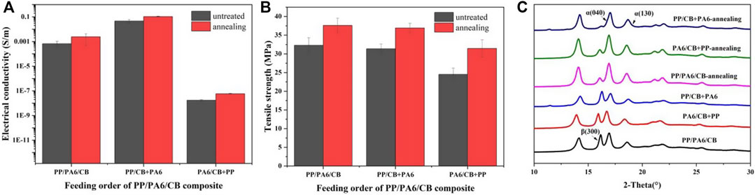
Figure 11. A comparison of the (A) electrical conductivity, (B) tensile strength and (C) XRD patterns of PP/PA6/CB microparts before and after annealing at 150°C for 1 h.
In this study, electrically conductive microparts with carbon black (CB)-rich network was constructed in situ by using polypropylene/polyamide 6 (PP/PA6) as the host matrix, under the processing conditions of microinjection molding (μIM). The prevailing high shear rates and extensional flow fields in μIM are unfavorable for the formation of intact filler network within micromoldings, as reflected by the lower electrical conductivity (σ) of microparts when compared with their compression molded counterparts. Samples which were prepared using PP/PA6 blend as the host substrate showed higher σ at relatively lower filler concentrations which suggested a higher efficacy of constructing filler network. The blending sequence and annealing treatment also affected the development of microstructure which determined the σ and tensile strength. This work provided insights into the preparation of electrically conductive microparts with reasonable mechanical performance that demonstrate potential applications in electronics and automotive sectors among others.
The original contributions presented in the study are included in the article/supplementary material, further inquiries can be directed to the corresponding authors.
XL: Writing–original draft, Visualization, Investigation, Formal Analysis. XG: Writing–review and editing, Investigation. JL: Writing–review and editing, Investigation. YS: Writing–review and editing. ML: Writing–review and editing, Project administration. HZ: Writing–review and editing, Supervision, Resources, Conceptualization. SZ: Writing–review and editing, Writing–original draft, Supervision, Project administration, Funding acquisition, Formal Analysis, Conceptualization.
The authors declare that financial support was received for the research, authorship, and/or publication of this article. This work was funded by the National Natural Science Foundation of China (52103040), and China Postdoctoral Science Foundation (2020M673217).
Prof. Yinghong Chen (The State Key Laboratory of Polymer Materials Engineering, Polymer Research Institute of Sichuan University) is appreciated for the use of MicroPower 5 microinjection molding machine.
Author YS was employed by Nanjing Chenguang Group Co., Ltd.
The remaining authors declare that the research was conducted in the absence of any commercial or financial relationships that could be construed as a potential conflict of interest.
All claims expressed in this article are solely those of the authors and do not necessarily represent those of their affiliated organizations, or those of the publisher, the editors and the reviewers. Any product that may be evaluated in this article, or claim that may be made by its manufacturer, is not guaranteed or endorsed by the publisher.
Abbasi, S., Carreau, P. J., and Derdouri, A. (2010). Flow induced orientation of multiwalled carbon nanotubes in polycarbonate nanocomposites: rheology, conductivity and mechanical properties. Polymer 51 (4), 922–935. doi:10.1016/j.polymer.2009.12.041
Abbasi, S., Derdouri, A., and Carreau, P. J. (2011). Properties of microinjection molding of polymer multiwalled carbon nanotube conducting composites. Polym. Eng. Sci. 51 (5), 992–1003. doi:10.1002/pen.21904
Agour, M., Riemer, O., Flosky, C., Meier, A., Bergmann, R. B., and Falldorf, C. (2016). Quantitative phase contrast imaging of microinjection molded parts using computational shear interferometry. IEEE Trans. Industrial Inf. 12 (4), 1623–1630. doi:10.1109/tii.2015.2481704
Ameli, A., Kazemi, Y., Wang, S., Park, C. B., and Pötschke, P. (2017). Process-microstructure-electrical conductivity relationships in injection-molded polypropylene/carbon nanotube nanocomposite foams. Compos. Part A Appl. Sci. Manuf. 96, 28–36. doi:10.1016/j.compositesa.2017.02.012
Baudouin, A.-C., Devaux, J., and Bailly, C. (2010). Localization of carbon nanotubes at the interface in blends of polyamide and ethylene–acrylate copolymer. Polymer 51 (6), 1341–1354. doi:10.1016/j.polymer.2010.01.050
Bokobza, L. (2019). Some applications of vibrational spectroscopy for the analysis of polymers and polymer composites. Polymers 11 (7), 1159. doi:10.3390/polym11071159
Cao, L., Yang, S., Gao, W., Liu, Z., Gong, Y., Ma, L., et al. (2013). Direct laser-patterned micro-supercapacitors from paintable MoS2 films. Small 9 (17), 2905–2910. doi:10.1002/smll.201203164
Chen, Q. Y., Xiang, Z., Yang, Q., Kong, M. Q., Huang, Y. J., Liao, X., et al. (2016). Flow-induced β-crystal of iPP in microinjection molding: effects of addition of UHMWPE and the processing parameters. J. Polym. Res. 23, 16. doi:10.1007/s10965-015-0910-4
Deng, H., Lin, L., Ji, M., Zhang, S., Yang, M., and Fu, Q. (2014). Progress on the morphological control of conductive network in conductive polymer composites and the use as electroactive multifunctional materials. Prog. Polym. Sci. 39 (4), 627–655. doi:10.1016/j.progpolymsci.2013.07.007
Ding, L., Ge, Q., Xu, G., Wu, T., Yang, F., and Xiang, M. (2017). Influence of oriented β-lamellae on deformation and pore formation in β-nucleated polypropylene. J. Polym. Sci. Part B Polym. Phys. 55 (23), 1745–1759. doi:10.1002/polb.24423
Ding, W. W., Chen, Y. H., Liu, Z., and Yang, S. (2015). In situ nano-fibrillation of microinjection molded poly(lactic acid)/poly(ε-caprolactone) blends and comparison with conventional injection molding. RSC Adv. 5 (113), 92905–92917. doi:10.1039/c5ra15402b
Fernandez-Ballester, L., Thurman, D. W., Zhou, W., and Kornfield, J. A. (2012). Effect of long chains on the threshold stresses for flow-induced crystallization in iPP: shish kebabs vs sausages. Macromolecules 45 (16), 6557–6570. doi:10.1021/ma3000384
Ferreira, T., Paiva, M. C., and Pontes, A. J. (2013). Dispersion of carbon nanotubes in polyamide 6 for microinjection moulding. J. Polym. Res. 20 (11), 301. doi:10.1007/s10965-013-0301-7
Giboz, J., Copponnex, T., and Mélé, P. (2007). Microinjection molding of thermoplastic polymers: a review. J. Micromechanics Microengineering 17 (6), R96–R109. doi:10.1088/0960-1317/17/6/r02
Gültner, M., Göldel, A., and Pötschke, P. (2011). Tuning the localization of functionalized MWCNTs in SAN/PC blends by a reactive component. Compos. Sci. Technol. 72 (1), 41–48. doi:10.1016/j.compscitech.2011.09.013
He, Y., Cao, Z., and Ma, L. (2015). Shear flow induced alignment of carbon nanotubes in natural rubber. Int. J. Polym. Sci. 2015, 1–8. doi:10.1155/2015/964723
Hoseini, A. H. A., Arjmand, M., Sundararaj, U., and Trifkovic, M. (2017a). Significance of interfacial interaction and agglomerates on electrical properties of polymer-carbon nanotube nanocomposites. Mater. Des. 125, 126–134. doi:10.1016/j.matdes.2017.04.004
Hoseini, A. H. A., Arjmand, M., Sundararaj, U., and Trifkovic, M. (2017b). Tunable electrical conductivity of polystyrene/polyamide-6/carbon nanotube blend nanocomposites via control of morphology and nanofiller localization. Eur. Polym. J. 95, 418–429. doi:10.1016/j.eurpolymj.2017.08.037
Hosseinpour, A., Nasseri, R., Ghiassinejad, S., Mehranpour, M., Katbab, A. A., and Nazockdast, H. (2019). Improving the electrical conductivity of ethylene 1-octene copolymer/cyclic olefin copolymer immiscible blends by interfacial localization of MWCNTs. Polym. Eng. Sci. 59 (3), 447–456. doi:10.1002/pen.24942
Huang, C. K., and Chiu, S. W. (2005). Formability and accuracy of micropolymer compound with added nanomaterials in microinjection molding. J. Appl. Polym. Sci. 98 (5), 1865–1874. doi:10.1002/app.21927
Jaber, E., Luo, H. B., Li, W. T., and Gersappe, D. (2011). Network formation in polymer nanocomposites under shear. Soft Matter 7 (8), 3852–3860. doi:10.1039/c0sm00990c
Li, D., Fei, G., Xia, H., Spencer, P. E., and Coates, P. D. (2015). Micro-contact reconstruction of adjacent carbon nanotubes in polymer matrix through annealing-Induced relaxation of interfacial residual stress and strain. J. Appl. Polym. Sci. 132 (38), 42416. doi:10.1002/app.42416
Liu, Z., Chen, Y. H., Ding, W. W., and Zhang, C. H. (2015). Filling behavior, morphology evolution and crystallization behavior of microinjection molded poly(lactic acid)/hydroxyapatite nanocomposites. Compos. Part A-Applied Sci. Manuf. 72, 85–95. doi:10.1016/j.compositesa.2015.02.002
Naficy, S., and Garmabi, H. (2007). Study of the effective parameters on mechanical and electrical properties of carbon black filled PP/PA6 microfibrillar composites. Compos. Sci. Technol. 67 (15-16), 3233–3241. doi:10.1016/j.compscitech.2007.04.001
Nazemi, H., Joseph, A., Park, J., and Emadi, A. (2019). Advanced micro- and nano-gas sensor Technology: a review. Sensors (Basel) 19 (6), 1285. doi:10.3390/s19061285
Pan, Y., Liu, X., Hao, X., Starý, Z., and Schubert, D. W. (2016). Enhancing the electrical conductivity of carbon black-filled immiscible polymer blends by tuning the morphology. Eur. Polym. J. 78, 106–115. doi:10.1016/j.eurpolymj.2016.03.019
Pötschke, P., Fornes, T. D., and Paul, D. R. (2002). Rheological behavior of multiwalled carbon nanotube/polycarbonate composites. Polymer 43 (11), 3247–3255. doi:10.1016/s0032-3861(02)00151-9
Pujari, S., Rahatekar, S. S., Gilman, J. W., Koziol, K. K., Windle, A. H., and Burghardt, W. R. (2009). Orientation dynamics in multiwalled carbon nanotube dispersions under shear flow. J. Chem. Phys. 130 (21), 214903. doi:10.1063/1.3139446
Ren, D. Q., Zheng, S. D., Wu, F., Yang, W., Liu, Z. Y., and Yang, M. B. (2014). Formation and evolution of the carbon black network in polyethylene/carbon black composites: rheology and conductivity properties. J. Appl. Polym. Sci. 131 (7), 39953. doi:10.1002/app.39953
Salehiyan, R., and Ray, S. S. (2018). Tuning the conductivity of nanocomposites through nanoparticle migration and interface crossing in immiscible polymer blends: a review on fundamental understanding. Macromol. Mater. Eng. 304 (2), 1800431. doi:10.1002/mame.201800431
Shen, Y., Zhang, T.-T., Yang, J.-H., Zhang, N., Huang, T., and Wang, Y. (2017). Selective localization of reduced graphene oxides at the interface of PLA/EVA blend and its resultant electrical resistivity. Polym. Compos. 38 (9), 1982–1991. doi:10.1002/pc.23769
Shi, S., Wang, L., Pan, Y., Liu, C., Liu, X., Li, Y., et al. (2019). Remarkably Strengthened microinjection molded linear low-density polyethylene (LLDPE) via multi-walled carbon nanotubes derived nanohybrid shish-kebab structure. Compos. Part B Eng. 167, 362–369. doi:10.1016/j.compositesb.2019.03.007
Shi, Y., Zhou, S., Zou, H., Liang, M., and Chen, Y. (2021). In situ micro-fibrillization and post annealing to significantly improve the tribological properties of polyphenylene sulfide/polyamide 66/polytetrafluoroethylene composites. Compos. Part B Eng. 216, 108841. doi:10.1016/j.compositesb.2021.108841
Simoncini, A., Tagliaferri, V., and Ucciardello, N. (2017). High thermal conductivity of copper matrix composite coatings with highly-aligned graphite nanoplatelets. Materials (Basel) 10 (11), 1226. doi:10.3390/ma10111226
Sultana, S. M. N., Pawar, S. P., and Sundararaj, U. (2019). Effect of processing techniques on EMI SE of immiscible PS/PMMA blends containing MWCNT: enhanced intertube and interphase scattering. Industrial Eng. Chem. Res. 58 (26), 11576–11584. doi:10.1021/acs.iecr.8b05957
Sumita, M., Sakata, K., Asai, S., Miyasaka, K., and Nakagawa, H. (1991). Dispersion of fillers and the electrical conductivity of polymer blends filled with carbon black. Polym. Bull. 25 (2), 265–271. doi:10.1007/bf00310802
Taguet, A., Cassagnau, P., and Lopez-Cuesta, J. M. (2014). Structuration, selective dispersion and compatibilizing effect of (nano)fillers in polymer blends. Prog. Polym. Sci. 39 (8), 1526–1563. doi:10.1016/j.progpolymsci.2014.04.002
Tanniru, M., and Tambe, P. (2022). Selective localization of rice husk derived graphene in reactive compatibilized PP/PA6 blends: influence on morphology, interface and mechanical properties. Fullerenes, Nanotub. Carbon Nanostructures 30 (2), 242–257. doi:10.1080/1536383x.2021.1929191
Wang, M., Ding, W. W., Xie, Y. P., Zhang, L. F., and Chen, Y. H. (2021). Effect of micro-mold cavity dimension on structure and property of polylactic acid/polycaprolactone blend under microinjection molding conditions. Polymers (Basel) 13 (6), 887. doi:10.3390/polym13060887
Whiteside, B. R., Martyn, M. T., Coates, P. D., Greenway, G., Allen, P., and Hornsby, P. (2004). Micromoulding: process measurements, product morphology and properties. Plastics, Rubber Compos. 33 (1), 11–17. doi:10.1179/146580104225018346
Wu, G., Li, B., and Jiang, J. (2010). Carbon black self-networking induced co-continuity of immiscible polymer blends. Polymer 51, 2077–2083. doi:10.1016/j.polymer.2010.03.007
Yang, H., Li, B., Wang, K., Sun, T., Wang, X., Zhang, Q., et al. (2008). Rheology and phase structure of PP/EPDM/SiO2 ternary composites. Eur. Polym. J. 44 (1), 113–123. doi:10.1016/j.eurpolymj.2007.10.028
Yu, F., Deng, H., Zhang, Q., Wang, K., Zhang, C., Chen, F., et al. (2013). Anisotropic multilayer conductive networks in carbon nanotubes filled polyethylene/polypropylene blends obtained through high speed thin wall injection molding. Polymer 54 (23), 6425–6436. doi:10.1016/j.polymer.2013.09.047
Zhang, H., Liu, H., and Zhang, N. (2022). A review of microinjection moulding of polymeric micro devices. Micromachines (Basel) 13 (9), 1530. doi:10.3390/mi13091530
Zhang, L., Wan, C., and Zhang, Y. (2009). Morphology and electrical properties of polyamide 6/polypropylene/multi-walled carbon nanotubes composites. Compos. Sci. Technol. 69 (13), 2212–2217. doi:10.1016/j.compscitech.2009.06.005
Zhang, M. Q., Yu, G., Zeng, H. M., Zhang, H. B., and Hou, Y. H. (1998). Two-step percolation in polymer blends filled with carbon black. Macromolecules 31 (19), 6724–6726. doi:10.1021/ma9806918
Zhang, X., Maira, B., Hashimoto, Y., Wada, T., Chammingkwan, P., Thakur, A., et al. (2019a). Selective localization of aluminum oxide at interface and its effect on thermal conductivity in polypropylene/polyolefin elastomer blends. Compos. Part B Eng. 162, 662–670. doi:10.1016/j.compositesb.2019.01.043
Zhang, Z., Cao, M., Chen, P., Yang, B., Wu, B., Miao, J., et al. (2019b). Improvement of the thermal/electrical conductivity of PA6/PVDF blends via selective MWCNTs-NH2 distribution at the interface. Mater. Des. 177, 107835. doi:10.1016/j.matdes.2019.107835
Zhao, C., Wang, J., Zhao, B., Chang, E., Lee, P. C., and Park, C. B. (2021). Electrically percolated nanofibrillar composites with core-sheath structures from completely wet ternary polymer blends. Chem. Eng. J. 419, 129603. doi:10.1016/j.cej.2021.129603
Zhao, Z. G., Yang, Q., Xi, S. T., Kong, M. Q., Huang, Y. J., and Liao, X. (2015). New understanding of the hierarchical distribution of isotactic polypropylene blends formed by microinjection-molded poly(ethylene terephthalate) and β-nucleating agent. RSC Adv. 5 (75), 61127–61136. doi:10.1039/c5ra10832b
Zhao, Z. G., Zhang, X., Yang, Q., Ai, T. T., Jia, S. K., and Zhou, S. T. (2020). Crystallization and microstructure evolution of microinjection molded isotactic polypropylene with the assistance of poly(ethylene terephthalate). Polymers (Basel) 12 (1), 219. doi:10.3390/polym12010219
Zhou, L., Tian, Y., Xu, P., Wei, H., Li, Y., Peng, H.-X., et al. (2021). Effect of the selective localization of carbon nanotubes and phase domain in immiscible blends on tunable microwave dielectric properties. Compos. Sci. Technol. 213, 108919. doi:10.1016/j.compscitech.2021.108919
Zhou, S., Hrymak, A., and Kamal, M. (2017a). Electrical and morphological properties of microinjection molded polypropylene/carbon nanocomposites. J. Appl. Polym. Sci. 134 (43), 45462. doi:10.1002/app.45462
Zhou, S., Hrymak, A., and Kamal, M. (2018a). Properties of microinjection-molded multi-walled carbon nanotubes-filled poly(lactic acid)/poly[(butylene succinate)-co-adipate] blend nanocomposites. J. Mater. Sci. 53, 9013–9025. doi:10.1007/s10853-018-2193-8
Zhou, S., Hrymak, A. N., and Kamal, M. R. (2016). Electrical and morphological properties of microinjection molded polystyrene/multiwalled carbon nanotubes nanocomposites. Polym. Eng. Sci. 56 (10), 1182–1190. doi:10.1002/pen.24352
Zhou, S., Hrymak, A. N., and Kamal, M. R. (2017b). Electrical, morphological and thermal properties of microinjection molded polyamide 6/multi-walled carbon nanotubes nanocomposites. Compos. Part A Appl. Sci. Manuf. 103, 84–95. doi:10.1016/j.compositesa.2017.09.016
Zhou, S., Hrymak, A. N., and Kamal, M. R. (2018b). Effect of hybrid carbon fillers on the electrical and morphological properties of polystyrene nanocomposites in microinjection molding. Nanomaterials (Basel) 8 (10), 779. doi:10.3390/nano8100779
Keywords: microinjection molding, immiscible blend, electrical conductivity, carbon black, microstructure
Citation: Lei X, Gong X, Li J, Shi Y, Liang M, Zou H and Zhou S (2024) Fabrication of electrically conductive microparts by constructing carbon black-rich network under high shear conditions in microinjection molding. Front. Mater. 11:1415283. doi: 10.3389/fmats.2024.1415283
Received: 10 April 2024; Accepted: 23 May 2024;
Published: 19 June 2024.
Edited by:
Jian Wang, Beijing University of Chemical Technology, ChinaReviewed by:
Ricardo Andrade, MackGraphe, BrazilCopyright © 2024 Lei, Gong, Li, Shi, Liang, Zou and Zhou. This is an open-access article distributed under the terms of the Creative Commons Attribution License (CC BY). The use, distribution or reproduction in other forums is permitted, provided the original author(s) and the copyright owner(s) are credited and that the original publication in this journal is cited, in accordance with accepted academic practice. No use, distribution or reproduction is permitted which does not comply with these terms.
*Correspondence: Shengtai Zhou, c3pob3VAc2N1LmVkdS5jbg==; Huawei Zou, aHd6b3VAc2N1LmVkdS5jbg==
Disclaimer: All claims expressed in this article are solely those of the authors and do not necessarily represent those of their affiliated organizations, or those of the publisher, the editors and the reviewers. Any product that may be evaluated in this article or claim that may be made by its manufacturer is not guaranteed or endorsed by the publisher.
Research integrity at Frontiers
Learn more about the work of our research integrity team to safeguard the quality of each article we publish.