 Huang Jianqiu1
 Jin Zhuo
 Li Xi
Li Xi
95% of researchers rate our articles as excellent or good
Learn more about the work of our research integrity team to safeguard the quality of each article we publish.
Find out more
ORIGINAL RESEARCH article
Front. Mater. , 26 June 2024
Sec. Structural Materials
Volume 11 - 2024 | https://doi.org/10.3389/fmats.2024.1401018
This article is part of the Research Topic Static and Dynamic Performance Analysis of Structures and Materials Under Complex Loads and Environmental Excitation View all 10 articles
The dynamic compaction method has been widely adopted in foundation treatment to densify the soil fillers. However, for the complexity of the impact behavior and soil mechanical properties, the theoretical research of dynamic compaction lags behind its practice for complex soil properties and stress paths. This paper presents a theoretical model applied to describe soil column plastic deformation under impact load. The relationship among stress increment, strain increment, and plastic wave velocity was derived from the aspect of propagation characteristics of stress waves in soil first. Combined with the Duncan-Chang Model, a one-dimensional theoretical model was established then. A numerical model was developed further to check the performance of the model. It showed that the deformation at the end of the soil column was mushroom-shaped. Both the axial and lateral deformation increased with the impact velocity. While some particles located at the side of the soil column end may splash under repeated impact. The theoretical deformations of the soil column were consistent with the experimental results both in the direction of axial and lateral.
During the construction of airports, roads, earth-rock dams, and similar projects, there is often a significant need for earth-rock filling engineering. To ensure the long-term safety and serviceability of geotechnical structures, it is essential to methodically place and compact earth or stone fillers layer by layer. A prominent technique utilized in this context is dynamic compaction, which employs heavy tampers weighing between 8 and 40 tons, dropped from heights of 10–20 m. This method delivers a powerful instantaneous impact load, rapidly densifying the fillers. Its widespread adoption is attributed to its high compaction efficiency, effective results, and low construction costs (Ye et al., 2020; Xu et al., 2022; Yao et al., 2022).
Significant investigations have been made, which mainly focus on the issue of the reinforcement mechanism of dynamic compaction (Zhang et al., 2017; Zhang et al., 2019; Wu et al., 2020), the depth of improvement (Dou et al., 2019; Li et al., 2020; Zhou et al., 2020), and factors affecting reinforcement efficiency (Li et al., 2018; Zhang et al., 2018; Jia et al., 2021; Zhou et al., 2022; Li et al., 2023). However, a notable gap exists between current dynamic compaction theory and practical engineering application, leading to a certain level of improvisation in the design and execution of dynamic compaction. This gap hinders the accurate determination of reinforcement effectiveness and assurance of compaction quality in filling projects. Some researchers have tried to explore the time-domain characteristics of the dynamic compaction process. Li et al. (Li et al., 2021; Li et al., 2024) focused on the tamper as their subject, simplifying the dynamic compaction process to an elastic-damping collision, establishing a time-domain model for the process, and introducing a novel method to determine the optimal number of tamping impacts, offering significant engineering value. S. Valliappa et al. (Valliappan et al., 1995) took the dynamic compaction process as a foundation subjected to harmonic loading, using Fourier transform methods to analyze the frequency domain characteristics of dynamic compaction vibrations in two dimensions. Kong and Yuan (Kong and Yuan, 1999) considered the soil as an elastic half-space and established the rigid body motion equations for the tamper.
Notably, the impact of dynamic compaction on the surface layer of soil generates stress waves that propagate to deeper layers, causing densification as the waves transmit. The impact energy gradually transforms into plastic deformation of the soil. Thus, the essence of soil reinforcement through dynamic compaction lies in the transformation of the kinetic energy carried by the tamper into plastic deformation of the soil via stress waves. Conducting theoretical research on dynamic compaction from the perspective of stress wave propagation and dissipation aligns more closely with the objective realities of soil reinforcement. Current research in dynamic compaction theory scarcely addresses this aspect.
This paper focuses on a simplified case of a one-dimensional soil column under impact load. A theoretical model is established to describe the deformation of the soil quantitatively under impact load. Combined with a numerical model, the paper validates the theoretical model’s applicability in describing both the axial plastic deformation and lateral deformation at the ends of the soil column. This provides a valuable reference for further establishing three-dimensional deformation models of soil under dynamic compaction and the mechanism of soil densification due to impact.
Compared to the soil column, the impact tamper typically is made of steel, can be assumed to have virtually infinite stiffness. Based on Newton’s Third Law and the principle of relative motion, when the impact tamper strikes the soil column at speed
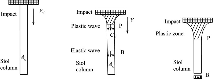
Figure 1. Schematic diagram of tamper impact on soil column.
The initial cross-sectional area of the soil column is denoted as
Considering that the stress on the contact surface between the soil column and a rigid plane is
According to the law of conservation of momentum:
where
Subsequently, substituting Eq. 1 into Eq. 3 and simplifying, we obtain:
The velocity of the plastic wave is:
By substituting Eq. 5 into Eq. 4 and simplifying, the relationship between
Integrating with the Duncan-Chang model, an explicit formula for the stress-strain relationship curve during the soil compression process is directly provided, as follows:
where
By substituting Eq. 8 into Eq. 6, the relationship between the maximum strain of the soil column and the impact velocity can be obtained:
To determine the axial plastic strain produced in the soil column due to the impact from a rigid object, Eq. 9 is therefore integrated as Eq. 10:
This yields:
From Eq. 11, the theoretical expression for the axial plastic strain of the soil column under the effect of initial impact velocity can be derived as follows:
As shown in Figure 1, the ends of the soil column undergo lateral deformation when impacted by a rigid planar tamper. At the boundary between elastic and plastic deformation, the soil column changes from the initial cross-sectional area
Thereby there is:
In Eq. 14,
By substituting Eq. 15 into Eq. 14, we can obtain:
By substituting Eq. 7 into Eq. 16, we can obtain:
From Eq. 17, the relative magnitude of the lateral deformation at the ends of the soil column, denoted as
Considering that the typical parameter values selected for soil columns should be compatible with the actual situation, let’s take
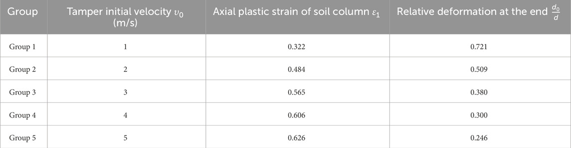
Table 1. Deformation of the soil column under different impact velocities.
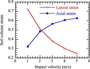
Figure 2. Relationship between deformation of soil columns and impact velocity.
Further impact tests on soil columns were conducted to verify the applicability of the established theoretical model. Considering the limitations of indoor tests, particularly the frictional impact between the soil column and rigid impactors, the article adopts numerical methods for the model’s applicability verification. Currently, numerical methods commonly include the Finite Element Method (FEM) and the Discrete Element Method (DEM). Some scholars have also developed the Material Point Method and Boundary Element Method based on FEM concepts. However, FEM requires the initial assumption of the soil’s constitutive model, which may not effectively serve the purpose of verifying the theoretical model. DEM divides the subject of study into independent units. Based on the interaction forces between these units and applying Newton’s Second Law of Motion, iterative methods like static or dynamic relaxation techniques are used for repeated cyclic calculations. These methods determine the force and displacement state of each unit at every time step, continually updating the position of all units. This makes DEM very adaptable in dealing with large deformations and even destructive processes. By tracking and calculating the micro-movement characteristics of each unit, DEM allows for large deformations, rotations, sliding, and separation in the soil body, thus realistically simulating the nonlinear large deformation characteristics within the soil.
When constructing the numerical model based on PFC, we first set the geometric boundary and determine the relevant properties of the particle material, and then determine the interaction law of particle-particle and particle-boundary. As shown in Figure 3, in this numerical simulation, the cylindrical soil particle units are represented using standard spherical particles as the basic discrete elements. The rigid impactor is simulated with a clump, composed of multiple particles rigidly bound together. The parameters in the following table are chosen with due consideration of the actual situation of fine-grained soils and the fact that the deformation of soils under ramming is studied in this paper. The basic parameters of the materials for both are presented in Table 2.
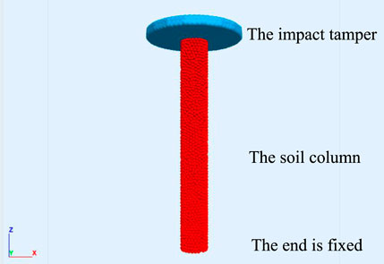
Figure 3. The schematic of the discrete element model.
Table 2. Basic parameters set of soil column and rigid impactor.
To achieve a uniformly dense soil column, a stratified under-pressure method was employed, generating particles in five layers to simulate the soil body. In order to prevent the occurrence of uneven initial internal stress within the soil column, once the entire column reached its designed height, the “solve aratio” command in PFC3D was utilized to allow the particles to self-balance under the influence of gravity. This ensures that the unbalanced force on each soil particle is less than 10−5N. Additionally, with a focus on computational efficiency of the model, 4,319 overlapping particles were collectively bound to simulate a rigid impact object, and 5,225 ball particles were used to model the soil column. Considering the mechanical characteristics of impact loading, a hysteresis damping model was adopted for the interactions between particles and between particles and the impact object. The model parameters were determined through extensive research and a comprehensive review of literature (as shown in Tables 2, 3).

Table 3. Contact model parameter values.
To test the applicability of the model, impact experiments were conducted using the established discrete element numerical model at five different initial velocities (respectively 1 m/s, 2 m/s, 3 m/s, 4 m/s, and 5 m/s). At the beginning of the experiment, the generated soil column was called upon and its lower end was fixed. The rigid impact object was positioned 5 cm above the top of the soil column and assigned a downward initial impact velocity. It's important to note that during the impact process, the acceleration due to gravity was zero, meaning that the effects of gravity were not considered. Throughout the impact, data such as the bulging at the ends of the soil column, changes in the length of the soil column, and other deformation data were recorded until the velocity of the rigid impact object reduced to zero, marking the completion of the impact process.
As shown in Figure 4, the deformation characteristics at the ends of the soil column, when subjected to impacts at various initial velocities, exhibit common features: The lateral deformation at the ends is greatest at the contact surface and gradually decreases further away. The deformed ends still maintain a circular shape, and the overall plastic deformation of the soil column presents a “mushroom shape” that is larger at the top and smaller at the bottom. More notably, there are differences in the deformation of the soil column ends under different impact velocities. Firstly, the axial plastic deformation of the soil column increases with the increase in impact velocity. In terms of lateral deformation, the deformation at the ends increases with increasing impact velocity. However, at excessively high velocities (v0 = 4.0 m/s, v0 = 5.0 m/s), a few particles at the impacted end of the soil column are observed to disintegrate, a phenomenon similar to the slight particle splashing observed in actual soil columns under impact.
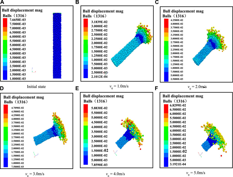
Figure 4. Deformation of the soil column under different impact velocity.
To verify the applicability of the theoretical model, a comparative analysis was conducted from two perspectives: the axial plastic strain of the soil column and the lateral deformation at its ends. Figure 5 illustrates the axial plastic deformation of the soil after impacts at different velocities. It is observed that as the impact velocity increases, the axial deformation also increases, albeit at a decreasing rate. Comparing theoretical and experimental values reveals good consistency across the five impact velocities, with the largest discrepancy occurring at an impact velocity of 2 m/s, where the difference between the experimental and theoretical values of axial deformation is only 4.2 mm. Regarding the lateral deformation at the ends of the soil column (Figure 6), the theoretical and experimental values under different impact velocities still show good agreement. The greatest difference occurs at an impact velocity of 5 m/s, which can be attributed to the disintegration and farther scattering of individual particles at the ends of the soil column under high-velocity impacts. Considering both axial and lateral deformations, it can be concluded that the theoretical values aptly describe the deformation characteristics of the soil column under impact. This finding has significant implications for further research into the deformation characteristics of foundations and subgrades under impact compaction.
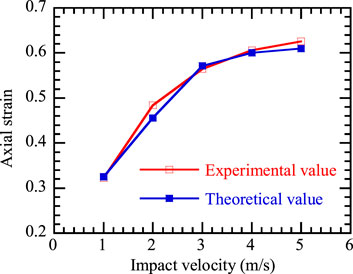
Figure 5. Axial plastic deformation of the soil column under different impact velocities.
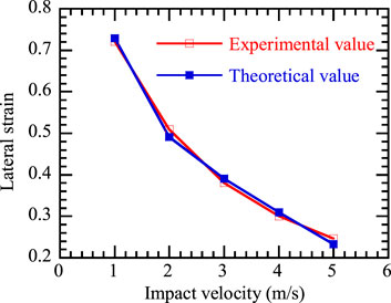
Figure 6. Lateral deformation at the ends of the soil column under different impact velocities.
A simple theoretical model was presented to describe a soil column plastic deformation under impact load. Results showed that the end of the soil column was mushroom-shaped after impact load. The lateral deformation at the end of the soil column is the biggest. Both the axial and lateral deformation increased with the impacting velocity. However, the axial deformation increment of the soil column decreases gradually, while the lateral deformation increment changes less. The good agreement between the theoretical estimated and experimental measured deformation verified the characteristics of the complex deformation for a soil column under impact load. This can help us to better understand the behavior of soil, prevent and mitigate the effects of geohazards and thus improve the quality and safety of our engineering design and construction. Future study can be carried out on the factors that affect the value of parameters of Duncan-Zhang model, including particle breakage, moisture content, particle size distribution.
The original contributions presented in the study are included in the article/Supplementary Material, further inquiries can be directed to the corresponding authors.
HJ: Investigation, Methodology, Writing–original draft. JZ: Formal Analysis, Investigation, Software, Validation, Writing–original draft. WH: Investigation, Methodology, Resources, Writing–original draft. LT: Conceptualization, Formal Analysis, Methodology, Software, Writing–original draft. PX: Resources, Validation, Visualization, Writing–original draft. TY: Data curation, Methodology, Resources, Writing–review and editing. LQ: Data curation, Formal Analysis, Writing–review and editing. LX: Funding acquisition, Supervision, Writing–review and editing.
The author(s) declare that financial support was received for the research, authorship, and/or publication of this article. This research was supported by the open fund of National Engineering Research Center of Highway Maintenance Technology (Changsha University of Science and Technology, NO. kfj210103) and the Science and Technology Talent Promotion Program of Hunan Province (No. 2023TJ-N12).
Authors HJ, WH, LT, PX, TY, and LQ were employed by China Railway Wuju Group the First Engineering Co., Ltd.
The remaining authors declare that the research was conducted in the absence of any commercial or financial relationships that could be construed as a potential conflict of interest.
All claims expressed in this article are solely those of the authors and do not necessarily represent those of their affiliated organizations, or those of the publisher, the editors and the reviewers. Any product that may be evaluated in this article, or claim that may be made by its manufacturer, is not guaranteed or endorsed by the publisher.
Dou, J. Z., Chen, J. J., and Wang, W. (2019). Method for estimating the degree of improvement in soil between adjacent tamping locations under dynamic compaction. Int. J. Geomechanics 19, 04019134. doi:10.1061/(ASCE)GM.1943-5622.0001530
Jia, M. C., Liu, B., Xue, J. F., and Ma, G. Q. (2021). Coupled three-dimensional discrete element–finite difference simulation of dynamic compaction. Acta Geotech. 16, 731–747. doi:10.1007/s11440-020-01055-y
Kong, L. W., and Yuan, J. X. (1999). Study on surface contact stress distribution properties for multi-layered foundation during dynamic consolidation. Chin. J. Theor. Appl. Mech. 31, 250. doi:10.6052/0459-1879-1999-2-1995-026
Li, X., Li, J., Ma, X. Y., Teng, J. D., and Zhang, S. (2018). Numerical study of the dynamic compaction process considering the phenomenon of particle breakage. Adv. Civ. Eng. 2018, 1–10. doi:10.1155/2018/1838370
Li, X., Lu, Y., Cui, Y., Qian, G., Zhang, J., and Wang, H. (2024). Experimental investigation into the effects of tamper weight and drop distance on dynamic soil compaction. Acta Geotech. 19, 2563–2578. doi:10.1007/s11440-023-02198-4
Li, X., Lu, Y. B., Qian, G. P., Yu, H. N., Zhang, J., Wang, H., et al. (2023). A new index for estimating the improved depth of dynamic compaction. Int. J. Geomechanics 24. Available at SSRN 4128740. doi:10.1061/ijgnai.gmeng-8705
Li, X., Yang, H., Zhang, J. Y., Qian, G. P., Yu, H. N., and Cai, Y. (2021). Time-domain analysis of tamper displacement during dynamic compaction based on automatic control. Coatings 11, 1092. doi:10.3390/coatings11091092
Li, X., Zhang, K. F., Ma, X. Y., Teng, J. D., and Zhang, S. (2020). New method to evaluate strengthen efficiency by dynamic compaction. Int. J. Geomechanics 20, 04020024. doi:10.1061/(ASCE)GM.1943-5622.0001586
Valliappan, S., Yazdi, J. T., and Zhao, C. (1995). Analytical solution for two-dimensional dynamic consolidation in frequency domain. Int. J. Numer. Anal. Methods Geomechanics 19, 663–682. doi:10.1002/nag.1610191002
Wu, S. F., Wei, Y. Q., Zhang, Y. Q., Cai, H., Du, J. F., Wang, D., et al. (2020). Dynamic compaction of a thick soil-stone fill: dynamic response and strengthening mechanisms. Soil Dyn. Earthq. Eng. 129, 105944. doi:10.1016/j.soildyn.2019.105944
Xu, P., Zhu, X., Qiao, S. F., Wang, G., and Yu, P. K. (2022). Field study of compaction quality control parameters and compaction mechanism of large particle size stone-filled embankment. Rock Mech. Rock Eng. 55, 3687–3702. doi:10.1007/s00603-022-02811-0
Yao, Z. Y., Zhou, C., Lin, Q. Q., Yao, K., Satchithananthan, U., Lee, F. H., et al. (2022). Effect of dynamic compaction by multi-point tamping on the densification of sandy soil. Comput. Geotechnics 151, 104949. doi:10.1016/j.compgeo.2022.104949
Ye, X. Y., Wang, S. Y., Zhang, S., Xiao, X., and Xu, F. (2020). The compaction effect on the performance of a compaction-grouted soil nail in sand. Acta Geotech. 15, 2983–2995. doi:10.1007/s11440-020-01017-4
Zhang, R. Y., Sun, Y. J., and Song, E. X. (2019). Simulation of dynamic compaction and analysis of its efficiency with the material point method. Comput. Geotechnics 116, 103218. doi:10.1016/j.compgeo.2019.103218
Zhang, S., Li, X., Teng, J. D., Ma, X. Y., and Sheng, D. C. (2017). A theoretical method for determining sample mass in a sieving test. Comput. Geotechnics 91, 12–16. doi:10.1016/j.compgeo.2017.06.004
Zhang, T. W., Cui, Y. J., Lamas-Lopez, F., Calon, N., and D’Aguiar, S. C. (2018). Compacted soil behaviour through changes of density, suction, and stiffness of soils with remoulding water content. Can. Geotechnical J. 55, 182–190. doi:10.1139/cgj-2016-0628
Zhou, C., Jiang, H. G., Yao, Z. Y., Li, H., Yang, C. Y., Chen, L. C., et al. (2020). Evaluation of dynamic compaction to improve saturated foundation based on the fluid-solid coupled method with soil cap model. Comput. Geotechnics 125, 103686. doi:10.1016/j.compgeo.2020.103686
Keywords: Duncan-Chang model, earth filling engineering, deformation of soil, dynamic compaction (DC), foundation treatment
Citation: Jianqiu H, Zhuo J, Haiping W, Tao L, Xuejun P, Yu T, Qin L and Xi L (2024) A theoretical model and verification of soil column deformation under impact load based on the Duncan-Chang model. Front. Mater. 11:1401018. doi: 10.3389/fmats.2024.1401018
Received: 14 March 2024; Accepted: 27 May 2024;
Published: 26 June 2024.
Edited by:
Ping Xiang, Central South University, ChinaReviewed by:
Xinyu YE, Central South University, ChinaCopyright © 2024 Jianqiu, Zhuo, Haiping, Tao, Xuejun, Yu, Qin and Xi. This is an open-access article distributed under the terms of the Creative Commons Attribution License (CC BY). The use, distribution or reproduction in other forums is permitted, provided the original author(s) and the copyright owner(s) are credited and that the original publication in this journal is cited, in accordance with accepted academic practice. No use, distribution or reproduction is permitted which does not comply with these terms.
*Correspondence: Jin Zhuo, emh1b2ppbkBzdHUuY3N1c3QuZWR1LmNu; Li Xi, bGl4aUBjc3VzdC5lZHUuY24=
Disclaimer: All claims expressed in this article are solely those of the authors and do not necessarily represent those of their affiliated organizations, or those of the publisher, the editors and the reviewers. Any product that may be evaluated in this article or claim that may be made by its manufacturer is not guaranteed or endorsed by the publisher.
Research integrity at Frontiers
Learn more about the work of our research integrity team to safeguard the quality of each article we publish.