- 1Department of Building Engineering, Energy Systems and Sustainability Science, Faculty of Engineering and Sustainable Development, University of Gävle, Gävle, Sweden
- 2Civil Engineering Department, Faculty of Engineering, Kafrelsheikh University, Kafrelsheikh, Egypt
- 3Department of Civil Engineering, College of Engineering and Architecture, Umm Al-Qura University, Makkah, Saudi Arabia
This study delves into the efficacy of external strengthening methods in improving the shear behavior of defected reinforced concrete (RC) beams that lack shear stirrups, utilizing both experimental and numerical methodologies. Failure risk of such beams is a potential threat which is mitigated carefully to increase building safety and sustainability to avoid risk of construction failure. Ten RC beams underwent three-point experimental testing to assess the influence of the strengthening scheme and the presence of mechanical anchors. Two beams were designated as control specimens, while eight beams were strengthened with the application of additional strain-hardening cementitious composite (SHCC) layer in various configurations. These configurations encompassed single-sided, two-sided, and strip applications, with the inclusion of mechanical anchors. The study found that employing a single-sided SHCC, incorporating vertically bent bars into the RC beam, is recognized for its efficient alleviation of degradation in shear reinforcement. The incorporation of three SHCC strips to partially reinforce the compromised beams demonstrated a modest impact on the initial stiffness. Nevertheless, noteworthy enhancements of 46% and 42% were observed in both cracking and ultimate loads, respectively. Furthermore, increasing the number of the SHCC strips to four resulted in a more significant improvement in the load–deflection responses. Enhancing the compromised beams by applying four SHCC strips to the beams using bolts offers a feasible alternative to the configuration where SHCC was uniformly attached along the entire defected zone. Moreover, a numerical model was created to simulate the tested beams. The model effectively anticipated the progression of cracks, ultimate capacity, and deflection, indicating excellent agreement with the experimental observations.
1 Introduction
Reinforced concrete (RC) structures require rehabilitation throughout their lifetime. They may also exhibit some defects that need strengthening or capacity improvement. Defects of RC members can be attributed to either human or natural reasons (Elsamak and Fayed, 2020; Zheng et al., 2021; El-Mandouh et al., 2022; Elsamak et al., 2022; Hamoda et al., 2023f; Abdallah et al., 2024; Ghalla et al., 2024b). Shear related defects are one of the most important issues that must be considered for RC beams. This type of defects can result in the unpreferable brittle failure, due to shear reinforcement problems, that should be avoided through strengthening and rehabilitation of defected RC beams (Muttoni and Fernández Ruiz, 2008; Basha et al., 2019; Autrup and Joergensen, 2021; Emara et al., 2023; Ghalla et al., 2024a). Strengthening the defected RC beams can mitigate their associated risks of failure which should be considered and managed carefully to increase building safety and sustainability, avoiding the creation of secondary subsequent risks which can cause construction failure.
In recent decades, various methods for strengthening structures have arisen, such as the externally bonded (EB) method (Mansour et al., 2024). This technique requires attaching steel or fiber reinforced polymer (FRP) composites along the outer face of the element, for prolonging their life cycle (De Lorenzis and Teng, 2007; Guo et al., 2021). In the EB strengthening technique, employing FRP composites provides various advantages, including a notable strength-to-weight ratio, preservation of structural member sections, straightforward application, and corrosion resistance. However, their drawbacks lie in the epoxy resin that binds the fibers. This is attributed to their high cost, inapplicability on wet surfaces, and a decrease in performance when exposed to fire (Gao et al., 2018; Tahmouresi et al., 2022).
The utilization of high-performance concretes is increasingly prevalent in the external rehabilitation of the RC structures, extending its application to the restoration of both concrete members and masonry elements (Tetta et al., 2015; Koutas et al., 2019; Alharthi et al., 2021; Giese et al., 2021; Larrinaga et al., 2022; Emara et al., 2024a; Emara et al., 2024b). In addition, the integration of fibers into these concretes has resulted in strengthened RC members demonstrating heightened fire resistance and enhanced adaptability to environmental surroundings. While the technique does cause a substantial improvement in stiffness as well as shear capacity of RC beams, the increase in deformability remains minimal (Gao et al., 2018; Tran et al., 2021). Numerous studies in the existing literature have investigated factors influencing this technique, including the thickness of layers, application strategy, and use of anchors (Triantafillou and Papanicolaou, 2006; Liu and Thermou, 2023).
The substitution of epoxy resins with textile reinforced mortar or fiber-reinforced cementitious matrix has indicated their effectiveness in externally reinforcing concrete elements (Elsanadedy et al., 2019). Nowadays, strain-hardening cementitious composites (SHCCs) are gaining increased prominence as a promising material for strengthening, owing to their enhanced characteristics in comparison to traditional concrete (Li et al., 1994; Emara et al., 2021; Abd et al., 2023; Abed et al., 2024; Hou et al., 2024). SHCCs are beneficial for their use as strengthening materials due to their numerous advantages. These include increased ductility, durability, enhanced toughness, reduced crack widths, improved energy dissipation, ease of application, compatibility, and mitigation of fire risks better than utilizing polymer-based materials (Pan et al., 2022). The use of reinforced SHCC layers for shear strengthening has notably improved shear capacity; however, instances of observed debonding failure have been documented (Zheng et al., 2021; Liu and Thermou, 2023). Employing mechanical anchors could offer a viable solution to prevent the identified debonding issue (Aljazaeri and Myers, 2017).
Sakr et al. (2019) studied the behavior of shear critical RC beams that were strengthened using reinforced and unreinforced precast ultra-high performance fiber concrete (UHPFC) plates over the entire length of the beams on one side with or without shear anchors. It was found that by strengthening the control beam along its entire length using an unreinforced plate with a thickness of 60 mm and without shear anchors, the capacity of the beam increased by 34%, and when utilizing the same plates but by reinforcing them transversely with a reinforcement ratio of 0.6%, the ultimate capacity of the control beam increased by 120%. This strengthening technique did not succeed in changing the failure pattern as the strengthened beams failed by debonding of the plates. Hekal et al. (2023) found that shear strengthening utilizing UHPFC plates on both sides along the entire length of the beam changed the failure mode to that of ductile bending and gave a higher capacity when compared to shear span strengthening only, which failed by debonding.
Mohamed et al. (2020) reported the failure by debonding of some shallow-wide beams strengthened externally by SHCC side plates. Hassan et al. (2020) studied the behavior of RC beams defected with openings in the shear span zone, which were strengthened with precast SHCC side plates as an alternative to the concrete side cover. The variables of the study were the effect of the dimensions of openings for un-strengthened beams, and effect of strengthening these beams using non-reinforced SHCC and SHCC reinforced with galvanized steel wire mesh. It was found that there was no failure by debonding of these plates and that strengthening using SHCC reinforced plates increased the ultimate capacity of the defected beam by 86.1%.
Hassan et al. (2021) investigated the behavior of shear critical T-shaped RC beams, which were strengthened using a U-shaped SHCC jacket reinforced transversely with different ratios. The parameters included beam preloading levels and the effect of shear crack injection using epoxy before the strengthening process. The transverse reinforcement of the SHCC layer was implanted at the bottom of the slab to prevent debonding. It was resulted that for beams that had not been previously loaded and by utilizing a SHCC jacket reinforced transversely with a ratio of 1.08%, failure by debonding was avoided and the beam’s ultimate capacity and ductility increased by 104% and 67%, respectively.
Baraghith et al. (2022) evaluated the behavior of RC beams with weak shear capacity and strengthened with SHCC strips reinforced with layers of glass fiber textile mesh (GFTM). To resist debonding, the SHCC strips were placed inside grooves drilled on the external surface of the beams. The investigation focused on the effect of the number of layers of reinforcement inside the strips, spacing between the strips, orientation angle of the strips, configuration of strengthening (sided-U-full wrap), and location of the strips in relation to the location of the internal stirrups. It was concluded that the use of the strips of SHCC reinforced with six layers of GFTM and applied to the beams externally aligned with the internal stirrups within the groove at a 90° orientation angle to the beams’ axis increases the beam’s ultimate capacity and ductility by 142% and 127%, respectively.
Baraghith et al. (2023) assessed the behavior of dapped-end beams strengthened with external or internal precast SHCC plates. The study examined the impact of using vertical or diagonal external side plates in the concrete cover zone, as well as the effect of employing internal diagonal plates of varying thicknesses. It was found that failure by debonding was avoided for all the beams. The beam internally strengthened with a precast SHCC plate inclined at an orientation of 45° was able to increase the shear capacity and ductility by 91% and 81%, respectively.
Khalil et al. (2023) strengthened RC deep beams in shear utilizing precast SHCC plates bonded using epoxy adhesive within grooves in the concrete cover zone. The variables were the effect of spacing between the plates, width of the plates, reinforcement of the plates, and applying prestressing to the plates. Failure by debonding was avoided, and the technique of employing precast prestressed reinforced plates of SHCC was able to increase the shear capacity and ductility by 68.5% and 225%, respectively.
This research indicates a notable absence of studies on the behavior of shear-critical RC beams that are externally strengthened with reinforced cast-in-situ SHCC plates/strips, specifically when applied to the shear span only. This study hypothesizes that the use of reinforced cast-in-situ SHCC for strengthening RC beams will enhance the shear performance, with variations in the application method (e.g., complete plates versus disconnected strips, internal versus external shear connectors, and one-sided versus two-sided strengthening) yielding distinct outcomes. The objective of this research is to validate this hypothesis through experimental tests and numerical simulations, providing insights that could lead to more efficient and effective strengthening techniques.
2 Experimental program
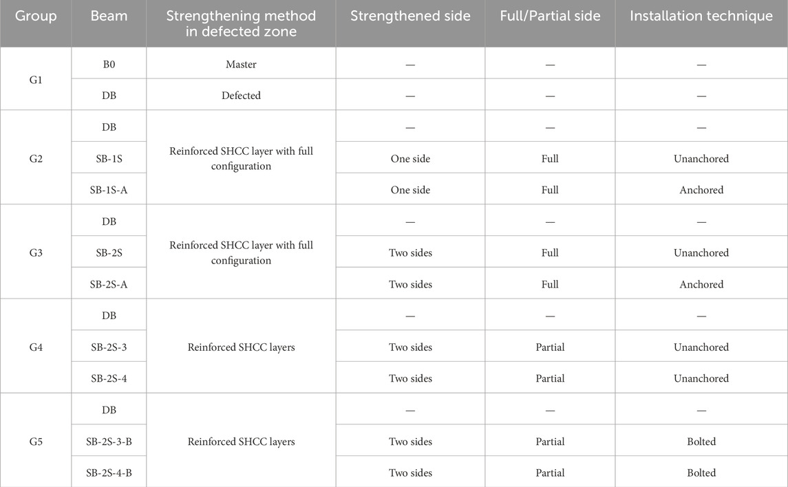
The research investigation was designed to assess the effectiveness of using external SHCC layers to enhance the shear performance of defected beams. The selection of the SHCC area and configuration were based on the hypothesis presented in Section 1. This hypothesis suggests that the method of the SHCC application whether through complete plates, disconnected strips, internal or external shear connectors, or one-sided versus two-sided strengthening could significantly influence the shear performance of RC beams. Consequently, the SHCC area was chosen to specifically target the shear-critical zones of the beams, ensuring that the tested configurations could effectively explore the anticipated variations in performance (Table 1). Figure 1 illustrates the analyzed normal concrete (NC) specimens featured a cross-section measuring 100 mm × 200 mm, a clear span of 1,300 mm, and an overall length of 1,500 mm. Each beam was reinforced with two steel reinforcement bars: 16 mm in diameter for tension and 10 mm in diameter for compression. The reference beam without defects (B0) was shear-reinforced with 8 mm stirrups space out at 100 mm intervals along its length, as depicted in Figure 1A. For the defected beam (DB) and strengthened beams, 8 mm stirrups were set apart every 100 mm along half of the beams, while the other half lacked shear reinforcements except for one central stirrup, utilized for aligning the longitudinal reinforcement (Figure 1B).
The experiment was organized into five sets, as detailed in Table 1. G1 comprised two RC beams, functioning as the control. The first beam (B0) served as the reference beam without any defects and was designed to collapse by flexure (Figure 1A), while the second beam (DB) represented a defected beam with shear zone weakness attributed to the absence of transverse stirrups, as shown in Figure 1B.
The subsequent groups (G2 to G5) consisted of two RC beams each and were designed to examine the influence of various strengthening configurations employing SHCC. G2 and G3 were strengthened with utilizing SHCC layer affixed to the defected beams throughout the entire length of the defected span (half of the beams). The primary distinction between the two groups lies in the application of the SHCC layers: G2 specimens were reinforced only on one side of the beams, as displayed in Figure 2. The need to strengthen the RC beams from one side appears when there is an obstacle in strengthening the other side of the beams, and this is evident in the beams adjacent to the neighbor’s buildings, while G3 specimens had SHCC layers applied to both sides of the beams, as demonstrated in Figure 3. Strengthening the bottom surface of the beams may be obstructed by architectural wall partitions, limiting strengthening to only the two sides of the beams. In the aforementioned two groups, the SHCC layers were strengthened by incorporating two horizontal 8 mm steel reinforcement bars, and in the vertical direction, 8 mm reinforcement bars were spaced at intervals of 100 mm. In one beam from each group, the vertical bars of SHCC were bent to secure them in the beam (Figures 2B, 3B). There were two purposes for bending these vertical bars inside the original beam. The first goal was to increase the bond of these bars within the SHCC layer by making their ends hooked instead of straight. The second goal was to strengthen the contact surface between the SHCC layer and the surface of the strengthened beams.
The last two groups, denoted as G4 and G5, involve the partial strengthening of the damaged zone through the incorporation of spaced SHCC layers, as indicated in Figures 4, 5. In each group, one beam underwent partial reinforcement on each side, employing three SHCC layers with a spacing of 325 mm, while the counterpart beam was partially strengthened on each side with four SHCC layers spaced at 217 mm intervals. The primary distinction between G4 and G5 lies in the utilization of anchor bolts in G5, connecting the SHCC layers to the beam, as depicted in Figure 5. This anchoring mechanism was not applied in G4, as illustrated in Figure 4. For partially strengthened RC beams, each SHCC layer was reinforced using two 8 mm vertical steel reinforcement bars. It is noteworthy to mention that the thickness of all SHCC layers was 25 mm.
In the beams of G2 and G3, side plates were not only used in the shear span zone but also extended to the end of the beams. To ensure a fair comparison and considering the anticipated increase in the beams’ ultimate capacity due to the strengthening process, strengthening strips were placed at the center of each support for the beams of G4 and G5 in anticipation of local collapses there. Fayed et al. (2020), Jumaa and Yousif (2019), and Cavagnis et al. (2015) concentrated stirrups internally in the region of each support to avoid local failure resulting from stress concentration.
Table 1 outlines the identification of the beams as follows: the initial designation, SB, signifies the strengthened beams, the second element denotes the number of reinforced sides (1S or 2S), and the final element, if present, includes, the letter A indicating anchored steel bars, the numbers 3 or 4 displaying the quantity of partially applied SHCC layers, and the letter B designating the use of anchor steel bolts.
2.1 Mix composition and materials characteristics
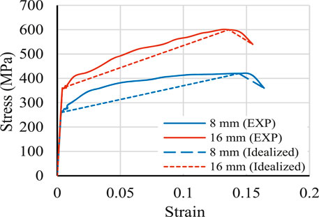
The components mentioned by Abdallah et al. (2024) were relied upon to prepare SHCC. Table 2 provides the proportions required for formulating both NC and SHCC. The manufacturing process utilized Type I ordinary Portland cement, and 10 mm aggregate size. In the production of SHCC, polyvinyl alcohol (PVA) discrete fibers, characterized by an aspect ratio of approximately 1,000 (length = 12 mm and diameter = 0.012 mm), were employed. According to the datasheet, the PVA strength in tension is 400 MPa with an elongation of 80%. Standard cylinders (150 mm × 300 mm), of NC and SHCC, were prepared for 28-day compression testing. The average values of three tested cylinders were 31.8 MPa and 64.4 MPa, respectively, referring to the average compressive strength of NC and SHCC, as presented in Figure 6. Furthermore, dog-bone shaped specimens, depicted in Figure 6, were fabricated and subjected to testing to ascertain the concrete strength in tension. NC exhibited brittle behavior under direct tension, failing abruptly upon reaching its maximum tensile strength of 3.27 MPa. Cracks propagated quickly without significant resistance, leading to sudden failure. In contrast, SHCC demonstrated superior performance. With a maximum tensile stress of 4.67 MPa, SHCC underwent multiple stages of deflection. Upon initial cracking, fiber bridging mechanisms redistributed stress, delaying crack propagation (Zeng et al., 2023; Zeng et al., 2024). This resulted in enhanced ductility and strain-hardening behavior, allowing SHCC to carry loads beyond its ultimate tensile strength. The stress–strain curves under direct tension for NC and SHCC are illustrated in Figure 6B. These curves have been simplified to facilitate numerical modeling work. Additionally, to characterize the employed steel reinforcement bars, direct tensile testing was conducted. The stress–strain curves attained from steel testing along with the idealized counterparts are displayed in Figure 7.
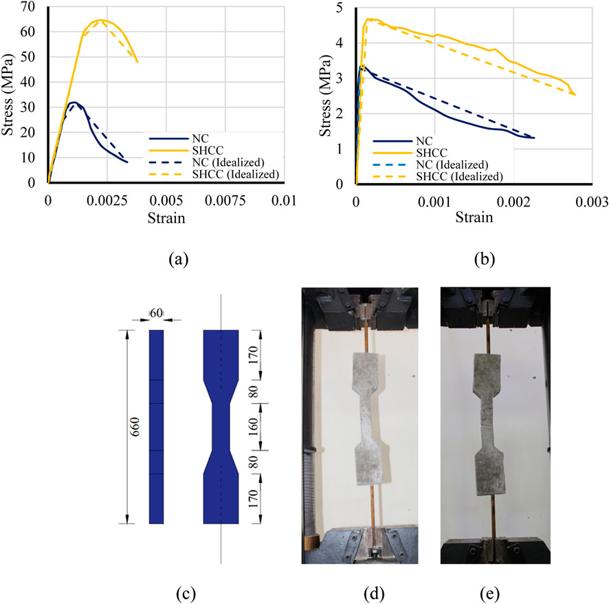
Figure 6. Direct tensile tests of concrete and SHCC: (A) compression stress–strain curve, (B) tension stress–strain curve, (C) specimens’ dimensions (Units: mm), (D) NC testing, and (E) SHCC testing.
2.2 Strengthening configurations
Figures 2–5 show the strengthening arrangements employed in the present study. In general, for all configurations, the surface slated for strengthening underwent adaptation post-concrete hardening. Subsequently, reinforcement bars were strategically positioned, followed by casting of SHCC after spraying epoxy adhesive onto the beams’ concrete surface, which was left to harden. In Figure 2A, SHCC was cast into wooden formwork affixed to one side of the beam. In Figure 2B, holes were drilled into the beam, and vertical reinforcement bars were bent and inserted, anchoring them with epoxy. Similar procedures to those in Figures 2A,B were followed in Figures 3A,B, respectively. However, the key distinction lies in SHCC being cast on both sides of the beam. Strengthening configurations presented in Figures 4, 5 involved adapting wooden formworks to produce the strips illustrated in the figures, after which SHCC was cast. For specimens featuring anchor bolts, following casting of SHCC, holes were drilled into the SHCC layer, extending into the beams. Subsequently, chemical epoxy was poured into these holes to secure the bolts. Afterward, steel bolts were inserted into the holes, as depicted in Figure 5B.
2.3 Setup arrangement and instrumentation
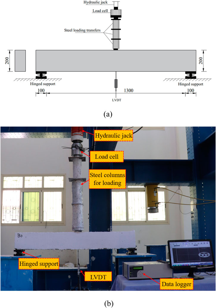
Each beam was experimented using three-point loading technique, shown in Figure 8, employing a deflection control mechanism until failure. Throughout various loading phases, the entire load–deflection response was meticulously documented utilizing a calibrated cell and LVDT that was strategically positioned opposite the loading point.
3 Experimental outcomes
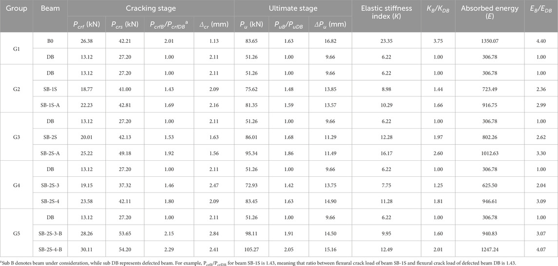
This section is concerned with presenting and analyzing experimental outputs, including Pcr, Δcr, Pu, ΔPu, K, E. The cracking load (Pcr) is the load corresponding to the occurrence of the first crack. If it occurs near the region of maximum moment, it is called flexural cracking load (Pcrf), and if it occurs in the region of maximum shear, it is called shear cracking load (Pcrs). It is worth noting that in the current study, the flexural crack load was always less than the shear crack load. Both load values are presented in Table 3. The cracking displacement (Δcr) is the vertical deflection corresponding to Pcr. The ultimate load capacity (Pu) is the maximum load that the beam can resist, after which the beam begins to enter the softening stage. The displacement at ultimate load (ΔPu) is the vertical deflection corresponding to Pu. The elastic stiffness (K) is the slope of the linear portion at the beginning of the load–deflection curve. The absorbed energy (E) is the area under the load–deflection curve. The load–deflection curve is the relationship between the total load acting on the beam and the deflection occurring at its middle below the load.
3.1 Cracks and failure inspection
In the case of the control beam, B0, the initial appearance of a flexural crack appeared at the midpoint at 26.38 kN, representing approximately 32% of its capacity. By increasing the load, additional flexural cracks emerged, extending vertically. With more loading, flexural-shear cracks initiated and propagated to the point of loading (Figure 9A). Ultimately, the beam experienced flexural failure at about 83.65 kN.
For the defected beam, DB, a major shear crack initiated in the defected zone near the support due to the absence of transverse shear stirrups, occurring at a shear cracking load (Pcrs) of approximately 27.20 kN. The flexural cracks occurred in the middle of the beam at a load of 13.12 kN. This value was roughly 50% lower than the cracking load observed in beam B0. With increasing load, additional cracks emerged within the defected region and progressed up to the point of the loading (Figure 9B). The observed failure was categorized as shear failure at an ultimate load of approximately 51.26 kN, marking a reduction of about 39% compared to the control beam. Notably, Figure 9B clearly demonstrated that if the cracks occurring in the zone containing stirrups are compared to those occurring in the defected zone (non-stirrup zone), the cracks are minor and are barely noticeable.
The crack patterns detected in G2, characterized by single-side strengthening, are displayed in Figure 10. A notable disparity in crack patterns was noted between the beams with and without anchoring. Beam SB-1S exhibited its initial crack at approximately 18.77 kN (43% greater than the defected beam DB). This crack originated in the SHCC layer along the shear region of the specimen, as indicated in Figure 10A. The crack extended, due to increased load, horizontally parallel to the reinforcement bars of the SHCC layer. With further loading, the crack inclined at a 45-degree angle upwards toward the loading point. Furthermore, flexural-shear cracks initiated at around 41 kN and propagated with continued loading. Additionally, at 67% of ultimate load (Pu), beam SB-1S experienced midspan flexural cracks that propagated vertically. However, despite the improvements in both Pcrf and Pu compared to beam DB, the beam had a brittle shear failure when reaching a load of approximately 75.62 kN.
Conversely, beam SB-1S-A, sharing the same strengthening configuration as beam SB-1S, except for the modification that involved bending the vertical reinforcement bars of the SHCC layer to create anchors within the beam, demonstrated an improved distribution of cracks, as depicted in Figure 10B. The initial crack initiation occurred at approximately 27% of the ultimate load (22.23 kN). With progressive loading, a succession of cracks developed across the beam, ranging from flexural to flexural-shear cracks. Upon reaching Pu, the beam had a preferable flexural failure. In comparison to SB-1S, beam SB-1S-A displayed a superior crack pattern and increased values for Pcrf and Pu by approximately 18% and 8%, respectively. The application of a single-sided SHCC, with vertically bent bars incorporated into the strengthened beam, was observed to effectively compensate for deterioration in the shear reinforcement, thereby enhancing both the critical Pcrf and Pu, as well as influencing the pattern of cracks.
Figure 11 presents the crack patterns observed in the beams of G3, featuring SHCC on both sides of the defected zone. For beam SB-2S, the first crack appeared within the strengthened zone at approximately 20.01 kN. Subsequently, multiple cracks initiated and propagated in a shear manner. In particular, a single crack emerged within the middle of the beam body at around 55 kN, progressing vertically, as illustrated in Figure 11A.
For beam SB-2S-A, cracks were observed in both the defected and undefected zones (Figure 11B). Within the defected zone, two primary cracks appeared, while flexural and shear cracks manifested in the undefected zone. The initial crack was detected at 25.22 kN, and failure occurred at 95.34 kN. The incorporation of vertical reinforcement bars as anchors in beam SB-2S-A resulted in a noticeable enhancement of both Pcrf and Pu by approximately 26% and 10%, respectively, when compared to beam SB-2S without anchors.
Beams SB-2S-3 and SB-2S-4 within G4 indicated their initial cracks at 19.15 kN and 23.58 kN, respectively. These cracks originated adjacent to the support of the defected zone and extended upwards in a shear manner, as depicted in Figure 12. As the load intensified, the cracks traversed the SHCC layers, and upon reaching the yielding stage, flexural cracks emerged in the center of the beam and propagated upwards. Beam SB-2S-4 (Figure 12B) exhibited a greater number of flexural cracks compared to SB-2S-3 (Figure 12A), attributed to its improved capacity resulting from the increased number of the SHCC strips. An almost similar trend was witnessed within G5 (Figure 13), wherein higher Pcrf values were recorded. Specifically, for SB-2S-3-B and SB-2S-4-B, Pcrf values were 28.26 kN and 30.11 kN, respectively.
3.2 Load–deflection, stiffness, and energy absorption
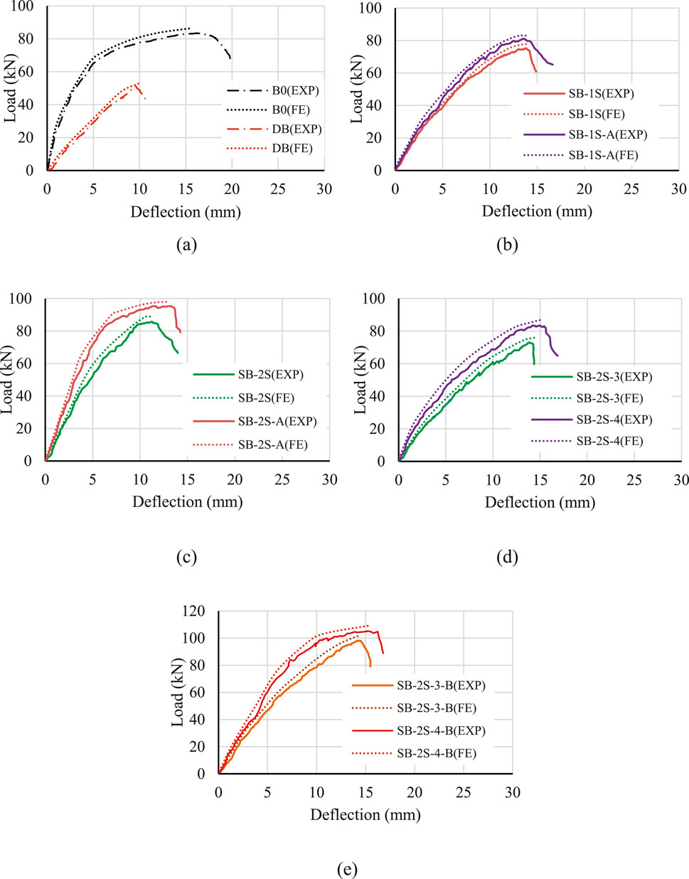
Load–vertical midspan deflection responses are shown in Figure 14 for all the specimens subjected to testing, while Table 3 presents the critical loading values recorded along with their subsequent midspan deformations at both the cracking and ultimate loading phases. In Figure 14A, the absence of shear reinforcement in the defected beam (DB) resulted in a significant reduction in initial stiffness, cracking, and ultimate loads compared to beam B0. Upon entering the cracking stage, a considerable decrease of approximately 50% in the cracking load was observed, coming with an 87% rise in the corresponding deflection. As the load continued to increase, beam B0 demonstrated a hardening characteristic before reaching its ultimate load, a behavior that was not observed in beam DB. The latter failed in a brittle shear manner within the defected zone owing to the absence of transverse stirrups. The recorded Pu of specimen DB was 38.7% lower than that of beam B0, with an elastic stiffness approximately 73.4% lower. Moreover, it is noteworthy that beam B0 exhibited a higher capacity to withstand deformation through its ultimate stage.
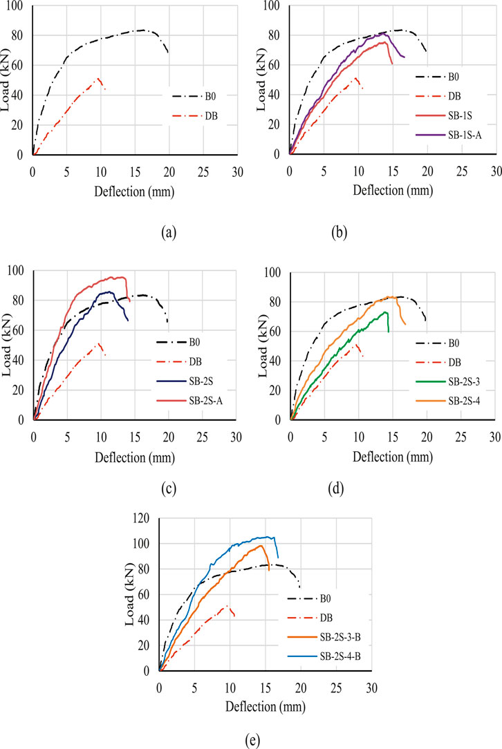
Figure 14. Load–deflection characteristics of tested beams: (A) G1, (B) G2, (C) G3, (D) G4, and (E) G5.
The implementation of a single-side SHCC layer remarkably improved the overall performance of strengthened beams compared to the defected one (Figure 14B). At initial loading stage, both SB-1S (without anchors) and SB-1S-A (with anchors) displayed nearly identical load–deflection behaviors until cracking. The observed Pcrf values were 18.77 kN for SB-1S and 22.23 kN for SB-1S-A. In the post-cracking phase, a slight divergence was noted between the two specimens considering the load–deflection until failure. The beam SB-1S-A indicated a Pu of 7.6% higher than SB-1S. Despite the improved crack pattern provided by SB-1S-A, it is worth to mention that the anchored bars did not yield significant enhancement compared to the unanchored beam. The average elastic stiffness of the strengthened beams was 55% higher than that of the defected beam but 59% lower than the undefected one. In essence, the enhancement provided falls within the range between the defected and undefected beams. Cracking and ultimate loads demonstrated average increases of approximately 56% and 53%, respectively, with respect to DB.
The application of the SHCC layers on both sides of the defected zone (G3) led to a more remarkable improvement for the compromised beam. In this scenario, the anchorage in beam SB-2S-A contributed greater enhancement to the overall behavior compared to beam SB-2S, which lacked anchorage, as depicted in Figure 14C. The recorded values of Pu and Pcrf for beam SB-2S were 86.01 kN and 20.01 kN, respectively, surpassing those of the defected beam, showcasing a significant 97.4% enhancement in initial stiffness, as presented in Table 3. By utilizing vertical reinforcement bars within the SHCC layer as anchors, the reinforced beam effectively mitigated the degradation observed in the defected beam, aligning its behavior closely with that of B0. This resulted in 14% improvement in capacity and successfully prevented debonding of the SHCC layer. According to Table 3, introducing the SHCC strips on one side of the damaged beam led to a 17% rise in midspan deflection at Pu for beam SB-2S and a 19% increase for beam SB-2S-A, in comparison to the defected beam. These values were notably 33% and 32%, respectively lower than those observed in the undefected beam.
Within G4, the partial strengthening of the compromised beam with three SHCC strips (SB-2S-3) exhibited a modest impact on the initial stiffness. Nevertheless, there was a noteworthy 46% enhancement in Pcrf, as displayed in Figure 14D. Subsequent to the development of cracks, the load–deflection stiffness experienced a slight augmentation up to an ultimate load of approximately 72.93 kN, marking a 42.3% increase with respect to DB, as illustrated in Table 3. Increasing the number of the SHCC strips to four led to more pronounced improvement in the load–deflection response compared to both DB and the beam strengthened with three SHCC strips, although it still remained below that of the control non-defected beam, as depicted in Figure 14D. The recorded Pu and Pcrf for beam SB-2S-3 were 42% and 46%, respectively, surpassing those of the defected beam, demonstrating a 25% improvement in initial stiffness, as provided in Table 3. The incorporation of either three or four SHCC strips gave greater deflection allowance for the reinforced beams. Specifically, the observed midspan deflection at Pu for beam SB-2S-3 was 42% higher than that of the defected beam and 18% less than that of the master one. Similarly, the observed midspan deflection at Pu for beam SB-2S-4 was 54% higher than that of the defected beam and 11% lower than the beam B0.
Figure 14E displays the load–deflection characteristics observed in specimens of G5, where strengthening involved the application of the SHCC strips in conjunction with chemical anchor bolts. Both beams, whether reinforced with two or three layers, indicated enhanced performance regarding stiffness, load capacity, and deformability. The initial stiffness of specimens SB-2S-3-B and SB-2S-4-B increased by 60% and 101%, respectively, compared to DB. Furthermore, Pu and Pcrf increased by 91% and 115%, respectively, for beam SB-2S-3-B, and by 105% and 129%, respectively, for beam SB-2S-4-B.
Upon comparing all the aforementioned groups, it is evident that G5 consistently presented higher load–deflection values at all loading stages. Following closely were the beams strengthened with the SHCC layers on both sides along the entire length of the shear span, as seen in G3, which illustrated the highest initial stiffness. The introduction of anchors connecting the additional SHCC layer to the defected zone enhanced the behavior and mitigated the risk of debonding of the strengthening layer. Moreover, the use of chemical anchor bolts in G5 yielded superior results when compared to the implementation of vertical reinforcement bars as anchors in G3. In addition, strengthening of the defected zone by affixing four SHCC strips to the beam using bolts (SB-2S-4-B) could serve as a viable alternative to applying SHCC over the entire length of the defected zone (SB-2S-A). It should be noted that, the presence of additional flexural reinforcement in the strengthening layer also affected the shear capacity of the strengthened beams.
It is noteworthy that regardless of the identified failure mode, the strengthening configuration applied in G5 could effectively compensate for the deficiency in shear stirrups and provide a higher capacity compared to B0.
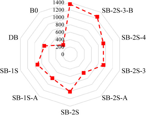
Figure 15 shows absorbed energy for each beam. The results revealed a significant improvement in absorbed energy when various strengthening configurations were applied, although all recorded values remained below that of beam B0. The most noticeable improvement was observed in beam SB-2S-4-B, utilizing four anchored SHCC strips, with a difference of only 7.5% compared to B0. Based on Table 3 and comparing to DB, the average increases in absorbed energy were 167%, 196%, 156%, and 257% for G2, G3, G4, and G5, respectively.
4 Numerical simulation
Numerical modeling possesses a distinctive capability to economize the time, expenses, and manpower typically associated with experimental testing. This attribute not only facilitates comprehensive parametric explorations but also enables the anticipation of structural element responses. The widely acclaimed structural analysis software, Abaqus, relies on the finite element method, renowned for its efficiency in both static and dynamic, and linear and nonlinear analyses. In this section, a numerical investigation was conducted on the behavior of RC beams featuring defected shear zones, examining both their strengthened and un-strengthened conditions through finite element modeling (FEM) utilizing the Abaqus program.
4.1 FEM designation and interactions
In the modeling stage, the 8-node C3D8R element (Elsamak et al., 2023; Alharthai et al., 2024) was employed simulating the loading and support plates, SHCC layers, and beams, as depicted in Figure 16. Conversely, the 2-node T3D2 truss element was used to indicate the stirrups and longitudinal reinforcement bars (Elsamak and Fayed, 2021; El-Mandouh et al., 2023; El Zareef et al., 2024). A mesh sensitivity analysis was performed on the model of the beam SB-2S-4 using mesh sizes of 25 × 25 mm, 15 × 15 mm, and 10 × 10 mm. The results indicated that a mesh size of 15 × 15 mm was optimal, balancing the accuracy with the efficiency of the analysis time.
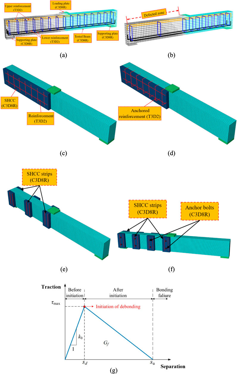
Figure 16. Setup of FEM for: (A) control specimen, (B) defected specimen, (C) G2, (D) G3, (E) G4, and (F) G5, and (G) bilinear traction–separation constitutive law.
The load was applied as a displacement to a reference point connected to the loading plate through the tie constraint. As displayed in Figure 16, the complete beam was modeled, with the left support being regarded as a roller and the other support as hinged. To simulate the behavior of the epoxy adhesive bonding SHCC to concrete, the cohesive-damaged interaction approach was utilized (Hamoda et al., 2023d; Abdallah et al., 2024; Salama et al., 2024a), which comprises three stages. Initially, it characterizes shear stiffness of this interaction. Then, it identifies the point where the maximum shear stress occurs on this surface, and finally, it describes the behavior of this interaction after reaching the maximum stress stage. The behavior of this interaction is presented in Figure 16G. According to Guo et al. (2005), the value of k0 can be estimated using the formula: k0 = 1/(ti/Gi + tc/Gc), where ti denotes the resin thickness, tc represents the concrete thickness, and Gi and Gc are the shear moduli of resin and concrete, respectively. A parametric analysis was performed to determine the optimal values for τmax and Gf (Figure 16G). Both numerical and experimental load–deflection curves, as well as collapse patterns, exhibited significant convergence when τmax was set to 1.5 MPa and Gf to 0.9 MPa. This finding is consistent with the result of Obaidat et al. (2010) and Hamoda et al. (2023b). Increasing the values of τmax and Gf resulted in a stronger interaction, leading to collapse patterns differing from those observed experimentally. The interaction between anchors or bolts and concrete surrounding them was modeled as a full bond–embedded region constraint. Conversely, the interaction between bolt head and SHCC involved a combination of hard contact, permitting separation behavior in the normal direction, and a penalty friction coefficient of 0.44 in the tangential direction. This approach has been widely adopted by numerous researchers (Shi et al., 2007; Shi et al., 2008; Wang et al., 2013; El-Khoriby et al., 2017; Hamoda et al., 2023c; Elsamak et al., 2024; Salama et al., 2024b). The connection between concrete and longitudinal bars and stirrups of reinforcement steel was upheld as an inclusive embedded restraint. In this configuration, steel constituted the embedded element, while concrete served as the host component. Additionally, a perfect bond was established between the beam and the support plates.
4.2 Simulation of materials
FEM employed the concrete damage plasticity (CDP) model to replicate the performance of NC and SHCC. The CDP model is adept at simulating the tensile and compressive concrete responses, crucial for assessing tensile cracking and compressive crushing (Emara and Hamoda, 2019; Hamoda et al., 2019; Hamoda et al., 2023a; Hamoda et al., 2023d; Hamoda et al., 2023e). The non-linear constitutive behavior of NC was defined based on Carreira and Chu (1985). Equation 1 delineates the stress–strain behavior under compression, while Equation 2 was used to predict the stress–strain response under tension.
In this scenario, fc and εco represent the maximum stress and strain in compression, while σc and εc designate the concrete stress and strain, respectively. The factor β can be estimated utilizing Equation 3.
Highly different from traditional concrete, SHCC exhibits remarkable characteristics such as high strain capacity in tension and efficient control of cracks. Consequently, a specialized model becomes imperative for a more precise simulation of the stress–strain response in SHCC. In this research, the compressive stress–strain of SHCC was emulated utilizing the model advocated by Zhou et al. (2015) through Equation 4. Moreover, Equation 5 was employed to replicate the bilinear stress–strain of SHCC.
Equation 4 defines σc and εc as the stress and strain, in compression, respectively. In addition, it includes εcp, which represents the compressive strain at the peak stress fc. The equation further introduces E0 as the elastic modulus. Equation 5 outlines σtc and εtc as the stress and strain, in tension, at crack initiation, while also incorporating σtu and εtu as the ultimate tensile stress and its consistent strain, respectively.
To optimize the factors of the CDP model, a sensitivity assessment was carried out, leading to determination of a dilation angle (ψ) set at 25° for NC and 30° for SHCC (Emara et al., 2022). The viscosity parameter (μ) plays a role in achieving convergence in Abaqus. μ = 0.00001 was selected, as values lower than this caused solution difficulties, while higher values produced load–deflection curves deviating from the desired behavior. The other parameters of the CDP model were chosen based on the default values recommended by Abaqus.
The elastic-plastic relationship was utilized to replicate the performance of steel encompassing both stirrups and reinforcement bars. This model was developed according to direct tensile testing results, as illustrated in Figure 7. The figure showcases the experimented and conceptualized stress–strain for steel components.
4.3 Finite element analysis outcomes
Validation of the FEM results was conducted by comparing them to the experimental observations, with a particular emphasis on the load–deflection relationship (Figure 17) and crack patterns (Figure 18). The results demonstrated the precision of FEM in predicting diverse aspects such as cracking, ultimate capacity, and deflection throughout all the stages.
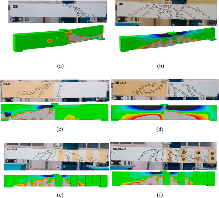
Figure 18. FEM versus experimental cracks inspection: (A) master beam, (B) non-stirrup beam, (C) G2, (D) G3, (E) G4, and (F) G5.
Numerically, the critical internal shear strengthening strains in the control beams, B0 and DB, as well as reinforcements within the SHCC layer of the strengthened beams, were traced at the locations indicated in Figures 1–5, labeled as S1. It is worth noting that these locations were selected because of their proximity to a potential shear crack. Figure 19 depicts the relationship between the strain of these elements and the total load of the beams.
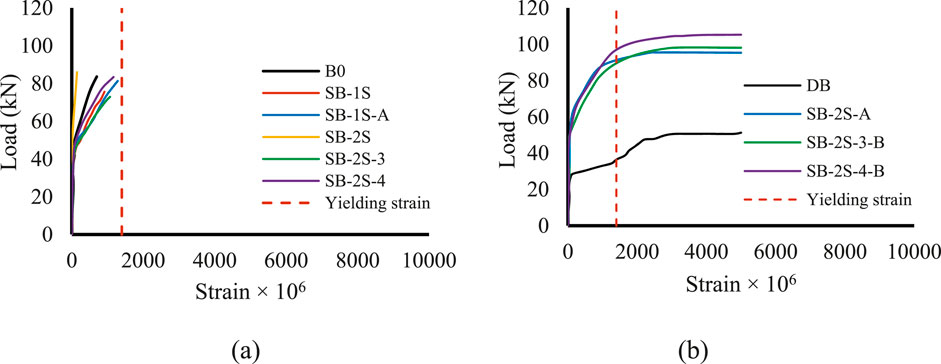
Figure 19. Relationship between load and strain for analyzed beams: (A) beams that did not reach yield stress level and (B) beams that exceeded yield stress level.
Figure 19A shows that the shear reinforcement strain did not reach the yield strain for some beams. This can be attributed to the avoidance of failure by shear, either due to flexural failure, as observed in beam B0, or collapse caused by debonding of the strengthening layer before the reinforcement within it reached the yield strain, as witnessed in beams SB-1S, SB-1S-A, SB-2S, SB-2S-3, and SB-2S-4. Figure 19B displays that the shear reinforcement in the remaining beams has indeed reached the yield strain. This confirms the occurrence of shear failure in beam DB and also validates the effectiveness of the strengthening method employed for beams SB-2S-A, SB-2S-3-B, and SB-2S-4-B. This is related to the non-debonding nature of the strengthening layer, confirming the occurrence of failure due to bending. Figure 20 illustrates the development of the cohesive shear stress with loading under the SHCC layer for beam SB-2S, confirming the occurrence of debonding of the SHCC layer.
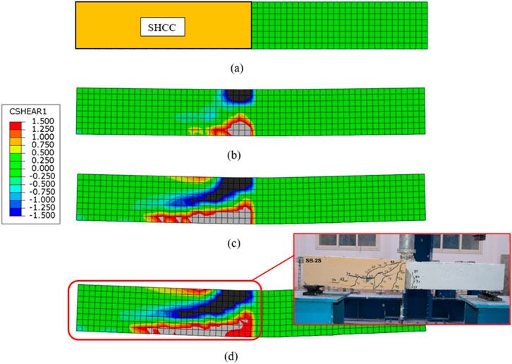
Figure 20. Development of cohesive shear stress with loading under SHCC layer for SB-2S: (A) 0% P, (B) 33% P, (C) 67% P, and (D) 100% P.
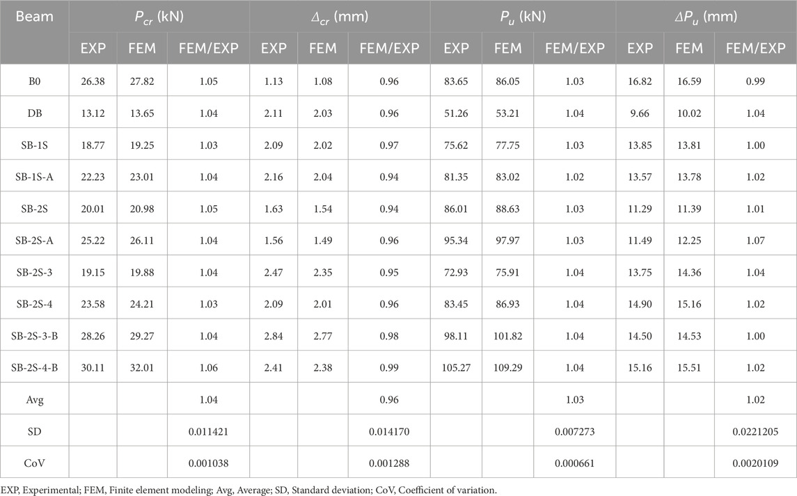
To enhance the clarity, Table 4 provides an assessment of the FEM results pertaining to critical parameters, including cracking and ultimate load, along with their associated deflections, in comparison to the experimental findings. During the cracking phase, the average ratios for the FEM-predicted cracking load to the experimentally observed load, as well as their respective deflection ratios, were 1.04 and 0.96, respectively. The standard deviations (SD) for these ratios were 0.0114 and 0.0142, with corresponding coefficients of variation (CoV) values of 0.001 and 0.0013, respectively. At the ultimate phase, the average ratios of the load and deflection were 1.03 and 1.02, respectively. The SD values were recorded at 0.0073 and 0.022, with CoV standing at 0.00066 and 0.002, as detailed in Table 4.
Furthermore, Figure 18 demonstrates the effective simulation of different failure modes and crack propagation by FEM, aligning well with the experimentally detected outcomes. Figures 18A,B exhibit the flexural failure of the control non-defected beam and the brittle shear failure of the defected one, respectively. Moreover, FEM precisely captured the effect of the SHCC layers’ configuration on the failure of the strengthened specimens (Figure 18).
5 Parametric study
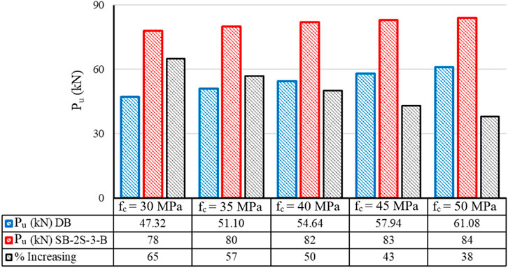
A parametric study was conducted utilizing a validated numerical model, as confirmed in Section 4. This study aims to explore the behavior of shear-defected RC beams with varying concrete strengths. Four beams, similar to the beam DB used in the experimental program, with concrete strengths of 30, 35, 40, 45, and 50 MPa, were considered as reference beams. All these beams were strengthened in a manner like the previously mentioned beam SB-2S-3-B. Figure 21 illustrates the ultimate load capacity of these beams before and after strengthening, as well as the percentage increase in their ultimate load capacity due to the strengthening process. It is observed that as the concrete strength of the reference beams increases, the effectiveness of the strengthening process decreases. For instance, the beam with a concrete strength of 30 MPa exhibited an ultimate load capacity of 47.32 kN before strengthening and 78 kN after strengthening, representing a 65% increase in the capacity. This increase drops to 38% for the beam with a concrete strength of 50 MPa.
6 Conclusion
This article investigated, through both experimental and numerical approaches, the efficacy of employing the SHCC layers for external strengthening RC beams lacking shear reinforcement which contributed to mitigate the risk severity of these RC beams. Ten RC beams were subjected to experimentation, and the evaluation of the strengthening configurations’ impact was made. The obtained findings can be summarized as below:
• Single-sided SHCC with vertically bent bars: The integration of vertically bent bars within a single-sided SHCC layer effectively mitigated shear reinforcement degradation, leading to significant improvements in Pcrf and Pu and positively influencing the crack pattern.
• Double-sided SHCC strengthening across the entire shear span: The use of vertical reinforcement bars as anchors in the SHCC layer proved effective in restoring the performance of the compromised beam, closely aligning it with the control beam (B0). This approach resulted in an 86% increase in the load capacity compared to the defected control beam and successfully prevented debonding of the SHCC layer.
• Partial reinforcement employing three SHCC strips: Applying three SHCC strips for partial reinforcement of the compromised beam had a modest impact on the initial stiffness, but it resulted in a substantial 46% improvement in Pcrf. There was a slight enhancement in the load–deflection stiffness in post-cracking, culminating in an ultimate load of approximately 72.93 kN, representing a 42% improvement in the beam DB.
• Enhanced reinforcement with four SHCC strips: Increasing the number of the SHCC strips to four remarkably improved the load–deflection response compared to both the defected beam and the beam reinforced with 3 strips, although it still did not reach the performance of the non-defected control beam. The achieved flexural cracking load Pcrf and Pu were 23.58 kN and 83.45 kN, respectively, demonstrating an 81% improvement in the initial stiffness over the defected beam.
• Deflection capacity with three or four SHCC strips: The application of either three or four SHCC strips allowed for greater deflection in the strengthened beams. The midspan deflection at the ultimate load for the beam with 3 strips was 42% higher than that of the defected beam and 18% lower than that of the control beam. Similarly, for the beam with 4 strips, the midspan deflection at Pu was 54% greater than that of the defected beam and 11% lower than that of the control beam.
• Alternative strengthening method using bolted SHCC strips: Strengthening the defected zone by affixing four SHCC strips utilizing bolts emerged as a viable alternative to the full-length SHCC application across the defected zone, offering similar improvements in the beam performance.
• Validation of the finite element model and parametric study: The proposed finite element model accurately replicated the behavior of the tested beams, effectively predicting their failure modes and crack patterns. The parametric study revealed that as the concrete strength increases, the effectiveness of the strengthening process decreases, with a 65% capacity increase observed for beams with 30 MPa concrete strength, compared to a 38% increase for the beams with 50 MPa concrete strength.
Data availability statement
The raw data supporting the conclusions of this article will be made available by the authors, without undue reservation.
Author contributions
AB: Conceptualization, Formal Analysis, Investigation, Methodology, Resources, Validation, Writing–original draft, Writing–review and editing. MG: Conceptualization, Investigation, Methodology, Validation, Writing–original draft. GE: Investigation, Writing–original draft. MB: Formal Analysis, Investigation, Methodology, Resources, Software, Writing–review and editing. EM: Formal Analysis, Writing–original draft. FA: Validation, Writing–original draft.
Funding
The author(s) declare that no financial support was received for the research, authorship, and/or publication of this article.
Conflict of interest
The authors declare that the research was conducted in the absence of any commercial or financial relationships that could be construed as a potential conflict of interest.
Publisher’s note
All claims expressed in this article are solely those of the authors and do not necessarily represent those of their affiliated organizations, or those of the publisher, the editors and the reviewers. Any product that may be evaluated in this article, or claim that may be made by its manufacturer, is not guaranteed or endorsed by the publisher.
References
Abd, S. M., Ibrahim, A. M., Hussein, O. H., Shamim, S., Qaidi, S., Najm, H. M., et al. (2023). Flexural behaviour of RC one-way slabs reinforced using PAN based carbon textile grid. Front. Mater. 10, 1070457. doi:10.3389/fmats.2023.1070457
Abdallah, A. M., Badawi, M., Elsamak, G., Hu, J. W., Mlybari, E. A., and Ghalla, M. (2024). Strengthening of RC beams with inadequate lap splice length using cast-in-situ and anchored precast ECC ferrocement layers mitigating construction failure risk. Case Stud. Constr. Mater. 20, e02747. doi:10.1016/j.cscm.2023.e02747
Abed, S., Hadi, R., Jawdhari, A., Mohammed Najm, H., Mahmood, S., Bilema, M., et al. (2024). Corrigendum: influence of ternary hybrid fibers on the mechanical properties of ultrahigh-strength concrete. Front. Mater. 10, 1359044. doi:10.3389/fmats.2023.1359044
Alharthai, M., Bahrami, A., Badawi, M., Ghalla, M., Elsamak, G., and Abdelmgeed, F. A. (2024). Numerical study on enhancing shear performance of RC beams with external aluminum alloy plates bonded using steel anchors. Results Eng. 22, 102143. doi:10.1016/j.rineng.2024.102143
Alharthi, Y. M., Emara, M., Elamary, A., and Sharaky, I. (2021). Flexural response and load capacity of reinforced concrete beams strengthened with reinforced mortar layer. Eng. Struct. 245, 112884. doi:10.1016/j.engstruct.2021.112884
Aljazaeri, Z. R., and Myers, J. J. (2017). Strengthening of reinforced-concrete beams in shear with a fabric-reinforced cementitious matrix. J. Compos. Constr. 21, 04017041. doi:10.1061/(asce)cc.1943-5614.0000822
Autrup, F., and Joergensen, H. B. (2021). Shear capacity of RC members without shear reinforcement: a modified crack sliding model. Eng. Struct. 239, 112147. doi:10.1016/j.engstruct.2021.112147
Baraghith, A. T., Khalil, A.-H. A., Etman, E. E., and Behiry, R. N. (2023). Improving the shear behavior of RC dapped-end beams using precast strain-hardening cementitious composite (P-SHCC) plates. Structures 50, 978–997. doi:10.1016/j.istruc.2023.02.059
Baraghith, A. T., Mansour, W., Behiry, R. N., and Fayed, S. (2022). Effectiveness of SHCC strips reinforced with glass fiber textile mesh layers for shear strengthening of RC beams: experimental and numerical assessments. Constr. Build. Mater. 327, 127036. doi:10.1016/j.conbuildmat.2022.127036
Basha, A., Fayed, S., and Elsamak, G. (2019). Flexural behavior of cracked RC beams retrofitted with strain hardening cementitious composites. KSCE J. Civ. Eng. 23, 2644–2656. doi:10.1007/s12205-019-1874-4
Carreira, D. J., and Chu, K.-H. (1985). Stress-strain relationship for plain concrete in compression. ACI Struct. J. 82, 797–804.
Cavagnis, F., Ruiz, M. F., and Muttoni, A. (2015). Shear failures in reinforced concrete members without transverse reinforcement: an analysis of the critical shear crack development on the basis of test results. Eng. Struct. 103, 157–173. doi:10.1016/j.engstruct.2015.09.015
De Lorenzis, L., and Teng, J.-G. (2007). Near-surface mounted FRP reinforcement: an emerging technique for strengthening structures. Compos. Part B Eng. 38, 119–143. doi:10.1016/j.compositesb.2006.08.003
El-Khoriby, S., Sakr, M. A., Khalifa, T. M., and Eladly, M. M. (2017). Modelling and behaviour of beam-to-column connections under axial force and cyclic bending. J. Constr. Steel Res. 129, 171–184. doi:10.1016/j.jcsr.2016.11.006
El-Mandouh, M. A., Elsamak, G., Rageh, B. O., Hamoda, A., and Abdelazeem, F. (2023). Experimental and numerical investigation of one-way reinforced concrete slabs using various strengthening systems. Case Stud. Constr. Mater. 18, e01691. doi:10.1016/j.cscm.2022.e01691
El-Mandouh, M. A., Hu, J. W., Shim, W. S., Abdelazeem, F., and Elsamak, G. (2022). Torsional improvement of RC beams using various strengthening systems. Buildings 12, 1776. doi:10.3390/buildings12111776
Elsamak, G., Abdullah, A., Salama, M. I., Hu, J. W., and El-Mandouh, M. A. (2022). Punching shear behavior of slabs made from different types of concrete internally reinforced with SHCC-filled steel tubes. Materials 16, 72. doi:10.3390/ma16010072
Elsamak, G., Elmasry, A. H., and Rageh, B. O. (2024). Numerical modelling of the behavior of bare and masonry-infilled steel frames with different types of connections under static loads. Comput. Concr. 33, 103–119. doi:10.12989/cac.2024.33.1.103
Elsamak, G., and Fayed, S. (2020). Parametric studies on punching shear behavior of RC flat slabs without shear reinforcement. Comput. Concr. 25, 355–367. doi:10.12989/cac.2020.25.4.355
Elsamak, G., and Fayed, S. (2021). Flexural strengthening of RC beams using externally bonded aluminum plates: an experimental and numerical study. 11. Adv. Concr. Constr. doi:10.12989/acc.2021.11.6.481
Elsamak, G., Salama, M. I., and Hamoda, A. (2023). Behavior of precast segmental beams made of high-strength concrete and ultra-high performance fiber concrete connected by shear keys technique. Arabian J. Sci. Eng. 48, 4907–4923. doi:10.1007/s13369-022-07193-7
Elsanadedy, H. M., Abbas, H., Almusallam, T. H., and Al-Salloum, Y. A. (2019). Organic versus inorganic matrix composites for bond-critical strengthening applications of RC structures–State-of-the-art review. Compos. Part B Eng. 174, 106947. doi:10.1016/j.compositesb.2019.106947
El Zareef, M. A., Ghalla, M., Hu, J. W., and El-Demerdash, W. E. (2024). Damage detection of lightweight concrete dual systems reinforced with GFRP bars considering various building heights and earthquake intensities. Case Stud. Constr. Mater. 20, e03191. doi:10.1016/j.cscm.2024.e03191
Emara, M., Elsamak, G., Ghalla, M., Hu, J. W., Badawi, M., and Salama, M. I. (2024a). Shear improvement of defected RC beams with sustainable aluminum boxes incorporating high performance concretes. Case Stud. Constr. Mater. 21, e03500. doi:10.1016/j.cscm.2024.e03500
Emara, M., El-Zohairy, A., Fekry, M., and Husain, M. (2022). Effect of using ECC layer on the flexural performance of RC beams previously strengthened with EB CFRP laminates. Sustainability 14, 16990. doi:10.3390/su142416990
Emara, M., Ghalla, M., Hu, J. W., Badawi, M., Mlybari, E. A., and Ahmed, S. O. (2024b). Enhancement of cantilevered RC beams exhibiting inadequate lap spliced reinforcement using sustainable reinforced ECC layers. Constr. Build. Mater. 428, 136272. doi:10.1016/j.conbuildmat.2024.136272
Emara, M., and Hamoda, A. (2019). Numerical modeling of time-displacement response of RC slab subjected to impact loading. IOSR J. Mech. Civ. Eng. 16, 11–20. doi:10.9790/1684-1605031120
Emara, M., Mohamed, H. A., Rizk, M. S., and Hu, J. W. (2021). Behavior of ECC columns confined using steel wire mesh under axial loading. J. Build. Eng. 43, 102809. doi:10.1016/j.jobe.2021.102809
Emara, M., Salem, M. A., Mohamed, H. A., Shehab, H. A., and El-Zohairy, A. (2023). Shear strengthening of reinforced concrete beams using engineered cementitious composites and carbon fiber-reinforced polymer sheets. Fibers 11, 98. doi:10.3390/fib11110098
Fayed, S., Basha, A., and Elsamak, G. (2020). Behavior of RC stepped beams with different configurations: an experimental and numerical study. Struct. Concr. 21, 2601–2627. doi:10.1002/suco.201900503
Gao, W., Dai, J.-G., and Teng, J. (2018b). Three-level fire resistance design of FRP-strengthened RC beams. J. Compos. Constr. 22, 05018001. doi:10.1061/(asce)cc.1943-5614.0000840
Gao, W.-Y., Hu, K.-X., Dai, J.-G., Dong, K., Yu, K.-Q., and Fang, L.-J. (2018a). Repair of fire-damaged RC slabs with basalt fabric-reinforced shotcrete. Constr. Build. Mater. 185, 79–92. doi:10.1016/j.conbuildmat.2018.07.043
Ghalla, M., Badawi, M., Mlybari, E. A., and Hu, J. W. (2024a). Enhancing shear strength of RC beams through externally bonded reinforcement with stainless-steel strips and FRCM jacket to mitigate the failure risk. Results Eng. 22, 102246. doi:10.1016/j.rineng.2024.102246
Ghalla, M., Mansour, W., Li, W., Wang, P., Badawi, M., and El Zareef, M. A. (2024b). Enhancing the punching performance of two-way RC flat slabs using different configurations of embedded aluminum sections: experimental program and numerical analysis. Constr. Build. Mater. 434, 136737. doi:10.1016/j.conbuildmat.2024.136737
Giese, A. C. H., Giese, D. N., Dutra, V. F. P., and Da Silva Filho, L. C. P. (2021). Flexural behavior of reinforced concrete beams strengthened with textile reinforced mortar. J. Build. Eng. 33, 101873. doi:10.1016/j.jobe.2020.101873
Guo, R., Ren, Y., Li, M., Hu, P., Du, M., and Zhang, R. (2021). Experimental study on flexural shear strengthening effect on low-strength RC beams by using FRP grid and ECC. Eng. Struct. 227, 111434. doi:10.1016/j.engstruct.2020.111434
Guo, Z., Cao, S., Sun, W., and Lin, X. (2005) “Experimental study on bond stress-slip behaviour between FRP sheets and concrete,” in FRP in construction, proceedings of the international symposium on bond behaviour of FRP in structures, 77–84.
Hamoda, A., Ahmed, M., Ghalla, M., Liang, Q. Q., and Abadel, A. A. (2023a). Flexural performance of precast circular reinforced concrete members with intermediate connection filled with ultra-high-performance-concrete. Case Stud. Constr. Mater. 19, e02386. doi:10.1016/j.cscm.2023.e02386
Hamoda, A., El-Mandouh, M. A., Ahmed, M., Abadel, A. A., Liang, Q. Q., and Elsamak, G. (2023b). Experimental and numerical studies of reinforced concrete stair beams strengthened with steel bars and plates. Eng. Struct. 297, 117037. doi:10.1016/j.engstruct.2023.117037
Hamoda, A., Elsamak, G., Emara, M., Ahmed, M., and Liang, Q. Q. (2023c). Experimental and numerical studies of reinforced concrete beam-to-steel column composite joints subjected to torsional moment. Eng. Struct. 275, 115219. doi:10.1016/j.engstruct.2022.115219
Hamoda, A., Emara, M., and Mansour, W. (2019). Behavior of steel I-beam embedded in normal and steel fiber reinforced concrete incorporating demountable bolted connectors. Compos. Part B Eng. 174, 106996. doi:10.1016/j.compositesb.2019.106996
Hamoda, A. A., Ahmed, M., Abadel, A. A., Ghalla, M., Patel, V. I., and Liang, Q. Q. (2023d). Experimental and numerical studies of circular precast concrete slender columns with intermediate connection filled with high-performance concrete. Structures 57, 105204. doi:10.1016/j.istruc.2023.105204
Hamoda, A. A., Eltaly, B., and Ghalla, M. S. (2023e). Numerical investigation on reinforced concrete closed curved beams subjected to internal pressure strengthened with sustainable material. ERJ. Eng. Res. J. 46, 233–247. doi:10.21608/erjm.2023.177856.1234
Hamoda, A. A., Eltaly, B. A., Ghalla, M., and Liang, Q. Q. (2023f). Behavior of reinforced concrete ring beams strengthened with sustainable materials. Eng. Struct. 290, 116374. doi:10.1016/j.engstruct.2023.116374
Hassan, A., Atta, A. M., and El-Shafiey, T. F. (2020). Restoration of the shear capacity for RC beams with web openings using precast SHCC plates. Structures 25, 603–612. doi:10.1016/j.istruc.2020.03.046
Hassan, A., Baraghith, A. T., Atta, A. M., and El-Shafiey, T. F. (2021). Retrofitting of shear-damaged RC T-beams using U-shaped SHCC jacket. Eng. Struct. 245, 112892. doi:10.1016/j.engstruct.2021.112892
Hekal, G. M., Salama, M. I., Elsamak, G., and Almaadawy, A. H. (2023). Shear behavior of RC beams strengthened with ultra-high-performance fiber-reinforced concrete using finite-element analysis. Asian J. Civ. Eng. 24, 71–91. doi:10.1007/s42107-022-00489-x
Hou, J., Bai, J., Mou, H., and Xiang, Z. (2024). Tensile properties and constitutive model of cost-effective multiscale hybrid fiber reinforced strain hardening cementitious composites. Front. Mater. 11, 1378089. doi:10.3389/fmats.2024.1378089
Jumaa, G. B., and Yousif, A. R. (2019). Size effect on the shear failure of high-strength concrete beams reinforced with basalt FRP bars and stirrups. Constr. Build. Mater. 209, 77–94. doi:10.1016/j.conbuildmat.2019.03.076
Khalil, A.E.-H. A., Atta, A. M., Baraghith, A. T., Behiry, R. N., and Soliman, O. E. (2023). Shear strengthening of concrete deep beams using pre-fabricated strain-hardening cementitious composite plates. Eng. Struct. 278, 115548. doi:10.1016/j.engstruct.2022.115548
Koutas, L. N., Tetta, Z., Bournas, D. A., and Triantafillou, T. C. (2019). Strengthening of concrete structures with textile reinforced mortars: state-of-the-art review. J. Compos. Constr. 23, 03118001. doi:10.1061/(asce)cc.1943-5614.0000882
Larrinaga, P., Garmendia, L., Chastre, C., and San-José, J.-T. (2022). Low-grade RC beams strengthened with TRM composite based on basalt, carbon and steel textiles: experimental and analytical study. Case Stud. Constr. Mater. 16, e00906. doi:10.1016/j.cscm.2022.e00906
Li, V. C., Mishra, D. K., Naaman, A. E., Wight, J. K., Lafave, J. M., Wu, H.-C., et al. (1994). On the shear behavior of engineered cementitious composites. Adv. Cem. Based Mater. 1, 142–149. doi:10.1016/1065-7355(94)90045-0
Liu, X., and Thermou, G. E. (2023). A review on the shear performance of reinforced concrete (RC) beams strengthened with externally bonded mortar-based composites. Structures 58, 105474. doi:10.1016/j.istruc.2023.105474
Mansour, W., Li, W., Ghalla, M., Badawi, M., and El Zareef, M. A. (2024). Improving the punching capacity of two-way RC flat slabs via external strengthening using various configurations of aluminum sheets. Constr. Build. Mater. 420, 135611. doi:10.1016/j.conbuildmat.2024.135611
Mohamed, Y. T., Taher, S.E.-D., Nagy, A., and Mahfouz, S. Y. (2020). Shear behavior of shallow-wide beams strengthened by external SHCC jacket. HBRC J. 16, 351–363. doi:10.1080/16874048.2020.1796083
Muttoni, A., and Fernández Ruiz, M. (2008). Shear strength of members without transverse reinforcement as function of critical shear crack width. ACI Struct. J. 105, 163–172.
Obaidat, Y. T., Heyden, S., and Dahlblom, O. (2010). The effect of CFRP and CFRP/concrete interface models when modelling retrofitted RC beams with FEM. Compos. Struct. 92, 1391–1398. doi:10.1016/j.compstruct.2009.11.008
Pan, B., Liu, F., Zhuge, Y., Zeng, J.-J., and Liao, J. (2022). ECCs/UHPFRCCs with and without FRP reinforcement for structural strengthening/repairing: a state-of-the-art review. Constr. Build. Mater. 316, 125824. doi:10.1016/j.conbuildmat.2021.125824
Sakr, M. A., Sleemah, A. A., Khalifa, T. M., and Mansour, W. N. (2019). Shear strengthening of reinforced concrete beams using prefabricated ultra-high performance fiber reinforced concrete plates: experimental and numerical investigation. Struct. Concr. 20, 1137–1153. doi:10.1002/suco.201800137
Salama, M. I., Elayat, A., Reda, M., and Elsamak, G. (2024a). Influence of concrete type on rigid pavement behavior under static loads. Innov. Infrastruct. Solutions 9, 15. doi:10.1007/s41062-023-01316-1
Salama, M. I., Hu, J. W., Almaadawy, A., Hamoda, A., Rageh, B. O., and Elsamak, G. (2024b). Behavior of simple precast high-strength concrete beams connected in the maximum bending moment zone using steel extended endplate connections. Steel Compos. Struct. 50, 627. doi:10.12989/scs.2024.50.6.627
Shi, G., Shi, Y., Wang, Y., and Bradford, M. A. (2008). Numerical simulation of steel pretensioned bolted end-plate connections of different types and details. Eng. Struct. 30, 2677–2686. doi:10.1016/j.engstruct.2008.02.013
Shi, Y., Shi, G., and Wang, Y. (2007). Experimental and theoretical analysis of the moment–rotation behaviour of stiffened extended end-plate connections. J. Constr. steel Res. 63, 1279–1293. doi:10.1016/j.jcsr.2006.11.008
Tahmouresi, B., Momeninejad, K., and Mohseni, E. (2022). Flexural response of FRP-strengthened lightweight RC beams: hybrid bond efficiency of L-shape ribbed bars and NSM technique. Archives Civ. Mech. Eng. 22, 95. doi:10.1007/s43452-022-00410-y
Tetta, Z. C., Koutas, L. N., and Bournas, D. A. (2015). Textile-reinforced mortar (TRM) versus fiber-reinforced polymers (FRP) in shear strengthening of concrete beams. Compos. Part B Eng. 77, 338–348. doi:10.1016/j.compositesb.2015.03.055
Tran, C. T. N., Nguyen, X. H., Le, A. T., Nguyen, H. C., and Le, D. D. (2021). Shear tests of GFRP-reinforced concrete beams strengthened in shear by textile reinforced concrete. Structures 34, 4339–4349. doi:10.1016/j.istruc.2021.10.045
Triantafillou, T. C., and Papanicolaou, C. G. (2006). Shear strengthening of reinforced concrete members with textile reinforced mortar (TRM) jackets. Mater. Struct. 39, 93–103. doi:10.1007/s11527-005-9034-3
Wang, M., Shi, Y., Wang, Y., and Shi, G. (2013). Numerical study on seismic behaviors of steel frame end-plate connections. J. Constr. Steel Res. 90, 140–152. doi:10.1016/j.jcsr.2013.07.033
Zeng, J.-J., Li, P.-L., Yan, Z.-T., Zhou, J.-K., Quach, W.-M., and Zhuge, Y. (2023). Behavior of 3D-printed HPC plates with FRP grid reinforcement under bending. Eng. Struct. 294, 116578. doi:10.1016/j.engstruct.2023.116578
Zeng, J.-J., Yan, Z.-T., Jiang, Y.-Y., and Li, P.-L. (2024). 3D printing of FRP grid and bar reinforcement for reinforced concrete plates: development and effectiveness. Compos. Struct. 335, 117946. doi:10.1016/j.compstruct.2024.117946
Zheng, A., Li, S., Zhang, D., and Yan, Y. (2021). Shear strengthening of RC beams with corrosion-damaged stirrups using FRP grid-reinforced ECC matrix composites. Compos. Struct. 272, 114229. doi:10.1016/j.compstruct.2021.114229
Keywords: failure risk mitigation, strengthening, shear, strain-hardening cementitious composite, externally bonded, reinforced concrete beam, mechanical anchor, finite element modeling
Citation: Bahrami A, Ghalla M, Elsamak G, Badawi M, Mlybari EA and Abdelmgeed FA (2024) Various configurations of externally bonded strain-hardening cementitious composite reducing shear failure risk of defected RC beams. Front. Mater. 11:1373292. doi: 10.3389/fmats.2024.1373292
Received: 19 January 2024; Accepted: 30 August 2024;
Published: 24 October 2024.
Edited by:
Viktor Gribniak, Vilnius Gediminas Technical University, LithuaniaReviewed by:
Jun-Jie Zeng, Guangdong University of Technology, ChinaMaurizio Guadagnini, The University of Sheffield, United Kingdom
Copyright © 2024 Bahrami, Ghalla, Elsamak, Badawi, Mlybari and Abdelmgeed. This is an open-access article distributed under the terms of the Creative Commons Attribution License (CC BY). The use, distribution or reproduction in other forums is permitted, provided the original author(s) and the copyright owner(s) are credited and that the original publication in this journal is cited, in accordance with accepted academic practice. No use, distribution or reproduction is permitted which does not comply with these terms.
* Correspondence: Alireza Bahrami, YWxpcmV6YS5iYWhyYW1pQGhpZy5zZQ==; Mohamed Ghalla, bW9oYW1lZF9zaGFiYWFuQGVuZy5rZnMuZWR1LmVn
 Alireza Bahrami
 Mohamed Ghalla
 Galal Elsamak
 Moataz Badawi3