 Jing Liu1,2
 Yawei Fang
94% of researchers rate our articles as excellent or good
Learn more about the work of our research integrity team to safeguard the quality of each article we publish.
Find out more
ORIGINAL RESEARCH article
Front. Mater. , 22 February 2024
Sec. Structural Materials
Volume 11 - 2024 | https://doi.org/10.3389/fmats.2024.1363206
This article is part of the Research Topic Structural Applications of Concrete with Recycled Solid Wastes and Alternatives for Cement View all 9 articles
Reinforced concrete bridge piers with round-ended sections are susceptible to bending, bending–shear, and shear failure after earthquakes in high-intensity areas, thus necessitating improved seismic performance. This study introduced a novel design for a concrete-filled steel tube (CFST) column, featuring a multi-chambered, round-ended cross-section. The use of longitudinal and transverse stiffeners divided the column section into distinct chambers, thereby enhancing the seismic performance of the columns. A total of 12 groups of static tests were performed to examine the effect of chamber layout, axial compression ratio, and aspect ratio on columns’ hysteresis behavior, and the hysteresis curves, skeleton curves, failure modes, stiffness degradation, ductility, and energy dissipation capacity were obtained. Results demonstrated the favorable seismic performance of composite columns. Additionally, an increase in chambers led to a full hysteresis curve, enhancing bearing and energy dissipation capacities. The displacement ductility coefficient (μ) ranged between 3.88 and 7.45, and the design parameters have minimal influence on the stiffness degradation of the composite beam. Based on the results, the long and short sides of the CFST columns with a large length–width ratio should be arranged to be relatively close in length.
Reinforced concrete (RC) bridge piers with round-ended sections are widely used as substructures in heavy-haul railway and long-span bridges. Over time, RC bridge piers in high-intensity areas generally experience post-earthquake bending, flexural shear, or shear failure; consequently, the seismic performance of these piers must be improved (Wang, 2015). Utilizing a concrete-filled steel tube (CFST) structure is an ideal choice to improve the seismic performance of RC bridge piers (Fei et al., 2020). During loading, the steel tube can provide effective restraints to the core concrete and retard the longitudinal cracking of the concrete under pressure; meanwhile, the internal concrete delays the local buckling of the steel tube. This synergy between those materials maximizes their benefits of mechanical properties, thereby leading to an increased static bearing capacity, ductility, and seismic performance of the bridge piers while promoting construction efficiency and cost effectiveness (Zhou et al., 2019; Hu et al., 2022a; Hu et al., 2022b; Zhou et al., 2022; Zhou et al., 2023).
Many bridges in earthquake-prone areas, such as the Houhu Bridge and Xinglin Bridge, have implemented CFST piers (Shen et al., 2020; Wang and Shen, 2023). A previous research conducted by the authors (Ding et al., 2016) demonstrated that when the section aspect ratio of a round-ended CFST column was greater than 5.0, the constraints to the core concrete by a single-cavity steel tube became negligible. Therefore, given the distinctive features of the large section length–width ratio of columns with circular sections in practical engineering, proposing a CFST column with a multichamber round-ended section in the current study is logical. The round-ended section is partitioned into multiple chambers by employing vertical and horizontal stiffening ribs. This design amplifies the restraining effect of the steel tubes on the core concrete through multicavity constraints, thereby bolstering the seismic performance of the column.
In recent years, some researchers have conducted experimental and numerical studies on the restraint mechanism of CFST columns with round-ended sections. Shen et al. (Shen et al., 2020) conducted an experimental study on axially loaded welded tubular joints with round-ended oval hollow sections (ROHS). They introduced a method for predicting the axial compression resistance of the ROHS tubular joint. Hassanein and Patel (Hassanein and Patel, 2018) completed a finite element analysis (FEA) on round-ended rectangular CFST short columns under axial compression, and on the basis of the results of FEA, a design model was established to estimate the reasonable strength of the columns under different loadings. Zhang et al. (Zhang and FuXu, 2020) established a fiber beam–column model to analyze the nonlinear behavior of round-ended CFSTs, and their model accurately described the nonlinear behavior of these round-ended CFSTs. Ren et al. (Ren et al., 2022) proposed a “central angle” concept to extend the cross-section design of round-ended rectangular CFST columns, and a reliable analytical model for predicting the axial ultimate bearing capacity of CFST was developed and validated. Shen et al. (Shen et al., 2022) investigated the performance of cold-formed round-ended CFST columns under cyclic loading using experimental and numerical approaches. Their research provided insightful revelations about the failure modes, hysteretic curves, ductility ratio, energy dissipation, stiffness, and strength degradation of these columns.
As for CFST columns with multiple cavities, Wu et al. (Wu et al., 2017) conducted tests on six columns under cyclic uniaxial compressive load, scrutinizing the effects of cavity construction, reinforcement arrangement, and concrete strength on failure characteristics, load-bearing capacity, stiffness, and residual deformation; moreover, a reasonable calculation method by dividing concrete into active and inactive confined regions was proposed. Qiao et al. (Qiao et al., 2018) executed a quasistatic test on four 1/30-scale uniquely shaped concrete-filled tube (CFT) columns with multiple cavities and investigated the seismic behavior of the CFT columns with multiple cavities under axial tension or axial compression. Wu et al. (Wu et al., 2016) studied the uniaxial compressive constitutive relationship of concrete confined by a special-shaped steel tube coupled with multiple cavities and proposed a method that predicts the associated complete stress–strain curves. Chen et al. (Chen et al., 2021) completed a comprehensive experimental study on the seismic behavior of prefabricated L-shaped CFST columns with rectangular multichamber columns under different lateral loading directions. The results indicated that multichamber, special-shaped steel tubes had a considerable restraining effect on the core concrete. Yin et al. (Yin et al., 2020) conducted experimental and analytical studies on the seismic behavior of special-shaped multichamber composite CFST columns. They proposed a theoretical method to predict the seismic behavior of the columns, and the calculation results showed good consistency with the test ones. Alatshan et al. (Alatshan et al., 2020) conducted a comprehensive study on the compressive performance of CFST columns with various reinforcement, partition, and tie rods. On the basis of the test results, the effects of these parameters on the mechanical properties of the composite columns were uncovered.
The foregoing literature review reveals that substantial research has been conducted on CFST columns with multiple chambers, but studies on CFST columns with multichamber round-ended cross-sections are few (Wu et al., 2016; Wu et al., 2017; Qiao et al., 2018; Alatshan et al., 2020; Yin et al., 2020; Chen et al., 2021). However, research on seismic properties is relatively limited, which restricts the application of this type of structure in high seismic-risk areas. Therefore, this study investigates the seismic performance of a CFST column with a multichamber round-ended cross-section. The main objectives of this study are as follows: (i) investigate the seismic performance of 12 CFST columns with a multichamber round-ended cross-section through a quasistatic experimental study and analyze the observed phenomena and failure patterns; (ii) analyze the effects of chamber layout, axial compression ratio, and section width–thickness ratio on the seismic performance, including hysteresis curve, skeleton curve, stiffness degradation, ductility and bearing capacity, and energy dissipation of columns; (iii) recommend reasonable structural measures for CFSTs.
In accordance with the specification for seismic test of buildings (JGJ101-2015) (GJ101-2015, 2015), a total of 12 CFST columns with a multichamber round-ended cross-section were tested in the current study. The test parameters for the composite columns are presented in Table 1. B is the width of the section, D is the height of the section, H is the height of the column, n is the axial compression ratio of the column, fcu is the cubic compressive strength, fs is the yield strength of steel tube, and ρs is the steel content of the section. Figures 1, 2 show the layouts and cross-section of the specimens, respectively.
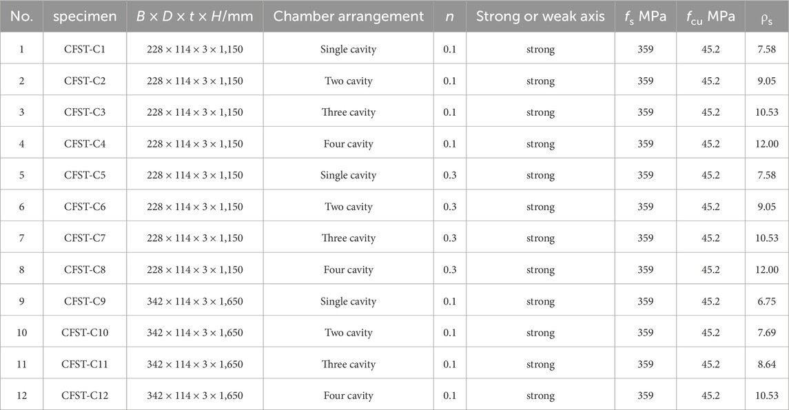
TABLE 1. The test parameters of composite columns.
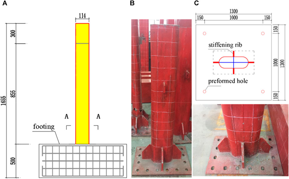
FIGURE 1. Layouts of the specimens. (A) Vertical view. (B) Actual photo. (C) Specimen base.
FIGURE 2. Cross-section of specimens.
During manufacturing, smooth, undistorted cross-sections at both ends of the steel tube must be ensured. A 20 mm-thick steel plate was welded to the bottom of the formed steel tube. Subsequently, concrete was poured and compacted by vibration after being pumped into the tube from the top. After 28 days of curing, the concrete had hardened completely and achieved its compressive strength. Then, the cover plate was welded to the top of the steel tube. For convenience of observation and recording of failure mode, red paint was sprayed on the external surface of the steel tube, and 50 mm × 50 mm white grids were plotted on the surface.
Commercial concrete (grade C40) was adopted for all the specimens, and the 28-day compressive strength obtained from nine standard concrete cubes with a dimension of 150 mm × 150 mm × 150 mm was measured as 45.2 MPa. The measured yield strength of the steel tube was 359 MPa, as listed in Table 1.
In this test, a pseudostatic test loading scheme was employed. The composite column test loading device is shown in Figure 3, and the loading process is shown in Figure 4. Specifics are outlined below:
(1) Before the test, approximately 30% of the axial force was applied to verify the stability of the connections among the jack, distribution beam, and specimen. The chuck of the specimen and the specimen itself must be properly secured. The designed axial compression load was applied to the specimen, maintaining a constant axial force value throughout the loading period.
(2) After the trial began, the control loads were 0.2 and 0.4 Pu; Pu represents the limit value of the horizontal load. Load control is employed until the specimen reaches the yield load, after which control is switched to deformation-based loading. Increments of 1Δy, 2Δy, 3Δy, 4Δy, 5Δy, 6Δy, 7Δy, 8Δy, and 9Δy were used for loading, where Δy = Pu/Ksec, Δy is the yield displacement of the specimen. Ksec is the secant stiffness of the load–displacement curve when the load reaches 0.4Pu.
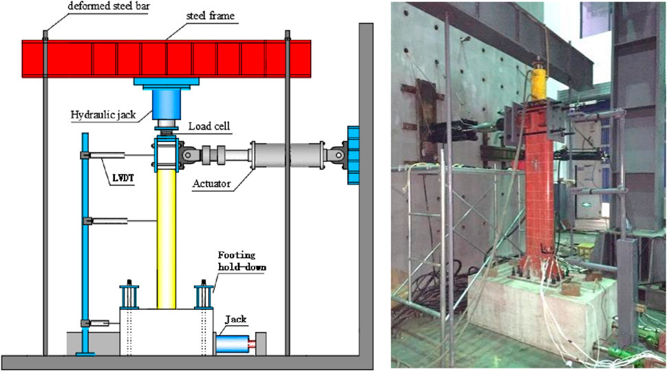
FIGURE 3. Experimental setup.
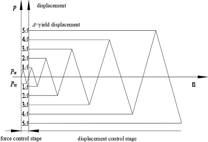
FIGURE 4. Loading protocol.
The measurements taken in this test primarily included horizontal load, vertical load, horizontal displacement at the top of the specimen, and strain on the steel tube’s surface. The main measurement points are arranged as follows:
Vertical load was applied to the specimen using a hydraulic jack. Three displacement meters are positioned along the column, and four displacement meters were placed on the concrete base. Figure 5 displays the displacement observations of the specimen.
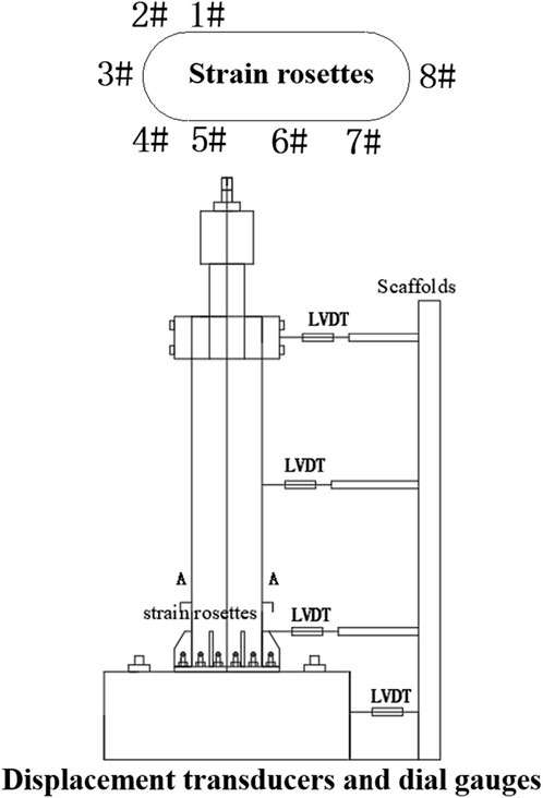
FIGURE 5. Layout of strain measurement.
Eight strain gauges were affixed 100 mm above the stiffener to measure the longitudinal and transverse strains on the surface of the steel tube during low-cycle loading, and data were collected by the DH3818. The locations of the strain measuring points on the steel tube section are illustrated in Figure 5.
The test results indicate that the failure modes of the specimens are essentially the same, characterized by bending failure. To illustrate the failure process of the specimen, we use CFST-C3 as an example, as depicted in Figure 6. 𝛥 represents the maximum displacement at various loading cycles.
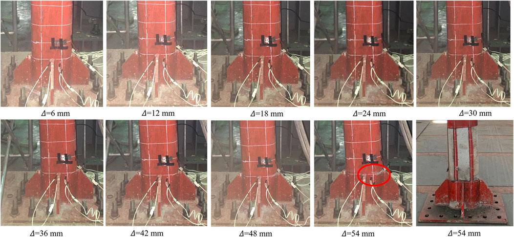
FIGURE 6. Failure process of specimen.
Before 𝛥 = 24 mm, no local buckling of the steel tube was observed on the surface of the steel tube. When the load exceeded the yield point, local buckling began to occur within 70 mm of the stiffener’s upper end at the specimen’s bottom. As the load increased, bulging appeared in the bottom part of the member, and surface deformation of the steel tube rapidly intensified as the specimen approached failure. The sound of the steel tube tearing and the crushing sound of the core concrete (e.g., at 𝛥 = 24 mm) were audible, indicating that the strain in the steel tube had reached its ultimate limit, and its tensile strength had been fully utilized.
The end of the CFST-C1–CFST-C12 test is shown in Figure 7. The fewer the chambers, the more severe the damage to the core concrete. In the case of single-cavity arranged steel tube concrete columns, the failure surface penetrates the entire concrete cross-section, while the presence of multicavity steel tubes constrains the failure of the core concrete in other specimens within their respective steel tube areas. Multicavity constraints can effectively delay and even prevent the occurrence of local buckling in steel tubes and concrete damage.
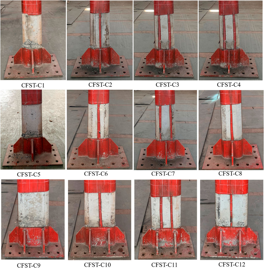
FIGURE 7. Failure modes.
The hysteresis curve provides a comprehensive reflection of the seismic performance of structures, indicating deformation characteristics, stiffness degradation, and energy dissipation capacity under pseudostatic loading. The test results reveal that the columns exhibit the same failure mode, characterized by bending failure. As the load surpasses the yield point, local buckling initiates within 100 mm of the upper end of the stiffener ribs at the bottom of the specimens. Therefore, the entire loading process can be divided into three stages: the elastic stage, the elastic–plastic stage, and the failure stage. To illustrate the complete loading procedure, we use CFST-C1 as an example, as shown in Figure 8.
(1) Elastic Stage (OA): In the initial loading stage, all the columns were in the elastic stage, as evidenced by the fact that the load–deflection curves closely followed a linear trend. The residual deformation was nearly zero after unloading. The flexural stiffness of the specimens remained relatively constant during this stage, indicating that the load increased rapidly while the horizontal deflection and strain increase were limited. Subsequently, as the horizontal deflection increased, the steel tube began to yield at point A.
(2) Elastic–Plastic Stage (AB): As the imposed load reached approximately 60% of the ultimate load or when the steel tube began to yield at point A, the load–deflection curves of all the columns began to deviate considerably from their initial linearity, exhibiting elastic–plastic behavior. In this phase, visible local buckling of the steel tube initially occurred above the stiffening ribs. Subsequently, the extent and severity of local buckling increased. At this point, a slight residual displacement became evident, and the stiffness of the specimens gradually degraded. The chamber arrangement and number considerably affected the hysteretic behavior of the columns. The greater the number of chambers, the later and less pronounced the local buckling of the steel tube becomes.
(3) Failure Stage (BC): Once the ultimate bearing capacity was reached (at point B), the maximum capacity at different loading cycles continuously decreased as the loading cycles increased. The flexural stiffness noticeably decreased, and the residual displacement increased rapidly. During this stage, the local buckling of the steel tube gradually spread to both sides, eventually forming a plastic hinge region as the loading cycles increased. Theoretically, the test was terminated when the load dropped below 85% of the peak load because of the accumulated damage to the core concrete and the increased local deformation of the steel tube.
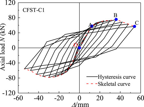
FIGURE 8. Typical skeleton curve of CFST-C1 columns under hysteretic loading.
Horizontal ultimate bearing capacity (𝑃u), displacement ductility index (DI), stiffness degradation (𝐾𝑖), and energy absorption (E) are primarily analyzed in this study. The ultimate bearing capacity (𝑃u) is an important index for investigating the seismic behavior of the columns, as established in extensive previous research. This value can be directly obtained from the experimental results, as shown in Figure 9. All other indices are calculated from the lateral load (P)-deflection (𝛥?) hysteresis and skeleton curves, which will be discussed in detail.
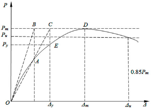
FIGURE 9. GMM method for searching the approximate yield point.
The displacement ductility index (DI) is also a critical parameter for understanding the hysteretic behavior of the columns. Therefore, it must be thoroughly investigated. DI is defined as the ratio of failure displacement (𝛥𝑢) to yield displacement (𝛥𝑦), as shown in Eq. 1:
The general yield moment method proposed in Ref (Ding et al., 2018). Is adopted to determine the yield displacement (Δy) or load (Py) for hysteretic curve envelopes without apparent yield point, as shown in Figure 9. In particular, the tangent lines of the curves at origin O and peak point D intersect at point B. A vertical line through point B intersected with a curve at point A. The line through points O and A intersected with the curve’s tangent through peak point D at point C. The vertical line through point C intersected with the curve at point E, the approximate yield point. Δu is the ultimate displacement corresponding to the load of 0.85Pmax in the postultimate stage.
Stiffness degradation refers to the phenomenon in which component stiffness decreases continuously with the increase in cycle times and displacement. Parameters such as chamber arrangement, axial compression ratio, and section width–thickness ratio affect the stiffness degradation rule of specimens. The ring stiffness of the specimen can be obtained through Eq. 2.
where Ki is the ring stiffness, Pij is the peak load for the ith loading cycle at the jth displacement ductility ratio, Δij is the corresponding peak displacement for the ith loading cycle at the jth displacement ductility ratio, and n is the cycle number.
The energy dissipation performance reflects the absorptive capacity of a structure under seismic load, which is usually measured by the area surrounded by the load–displacement hysteresis curve in the test. With the deformation conditions unchanged, the larger the area contained by the hysteresis curve, the better the energy dissipation performance of the specimen. Figure 10 shows the calculation figure of an equivalent viscous damping index. Many indexes can be used to measure energy dissipation capacity (e.g., energy dissipation coefficient and equivalent viscous damping coefficient). The energy dissipation factor E can be measured by the hysteretic energy dissipation in a single week, as defined in Eq. 3:
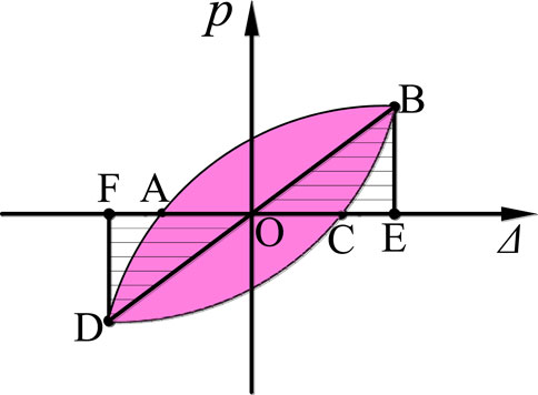
FIGURE 10. Experimental setup.
Figure 11 shows the effect of chamber arrangement on seismic properties. Figure 12 illustrates comparisons of capacity, ductility, and energy dissipation index.
(1) The hysteretic curves of all specimens are relatively full, with no pinching phenomenon, indicating good seismic performance. The chamber layout considerably influences the hysteresis curve. The more chambers there are, the fuller the hysteresis curve becomes, and the better the seismic energy dissipation. The displacement ductility coefficient ranges from 3.88 to 7.45.
(2) Compared with the bending bearing capacity of single-cavity columns, three-cavity, and four-cavity columns increased by 14.7%, and 25.2%, respectively, while that of the two-cavity columns decreased by 3.1% because the intermediate steel plate in the two-chamber arrangement is located near the neutral axis in the bending area, which has minimal influence on the section’s bending bearing capacity. The higher the axial compression ratio, the greater the bearing capacity.
(3) More chambers in the arrangement lead to greater elastic stiffness. The flexural stiffness could be obtained from the load–deflection curves under monotonic loading, while under dynamic cyclic loading, the flexural stiffness could be attained as the secant stiffness at 0.6 times the ultimate load using the skeletal curve. Compared with the single-cavity column, two-cavity, three-cavity, and four-cavity columns were larger by 3.1%, 11.0%, and 14.1%, respectively, because the elastic modulus of steel is much greater than that of concrete, and the increase in steel content can remarkably increase the flexural stiffness of the member. As displacement increases, the specimen’s stiffness gradually decreases.
(4) The more chambers the specimen has, the greater the energy dissipation. This relationship reflects the influence of chamber layout on structural energy dissipation. Compared with the single-cavity column, the energy dissipation of the three-cavity, and four-cavity columns were larger by, 5.9%, and 11.6%, respectively. However, the energy dissipation of two-cavity columns decreased by 1.0%
(5) The midpoint of the arc is selected to minimize the influence of welding on the strain measurement points. The axial stress–strain curves of the steel tube at each point of the model exhibit certain hysteresis under different chamber conditions.
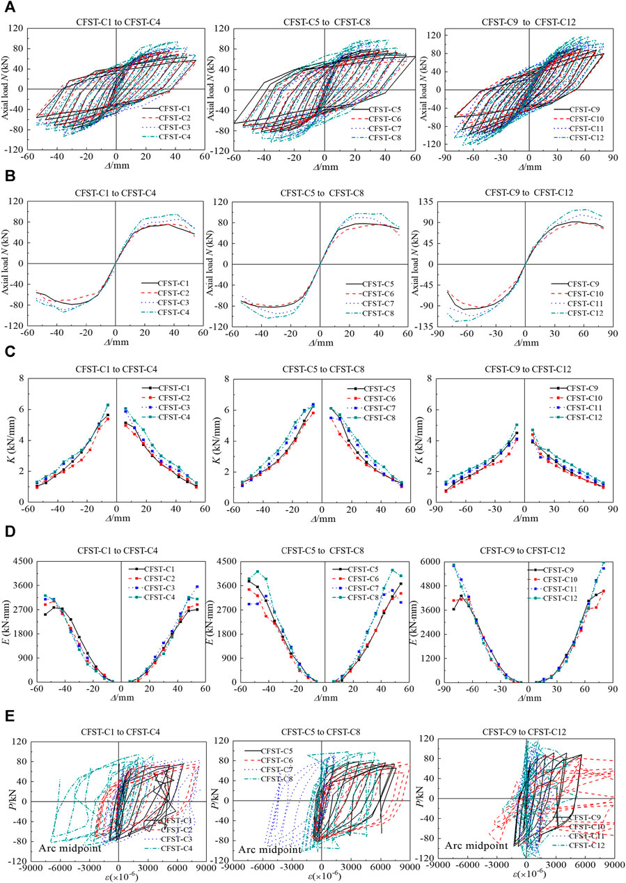
FIGURE 11. Effect of chamber arrangement on seismic property. (A) Hysteresis curve. (B) Skeletal curve. (C) Stiffness degradation. (D) Energy absorption. (E) Hoop strain.
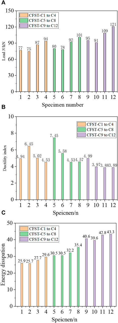
FIGURE 12. Comparisons of capacity, ductility, and energy dissipation. (A) Capacity. (B) Ductility index. (C) Energy dissipation.
Figure 13 shows the effect of axial compression ratio on seismic property.
(1) The hysteresis curves of specimens with axial compression ratio n = 0.3 are fuller than those with axial compression ratio n = 0.1. The higher the axial compression ratio, the larger the bearing capacity of the specimen. The average bearing capacity of CFST-C5–CFST-C8 is 5.2% larger than that of CFST-C1–CFST-C4. A high axial compression ratio of the specimen corresponds to high stiffness.
(2) The axial compression ratio considerably influences the plastic energy dissipation of specimens. CFST-C5–CFST-C8 is 18.2% larger than CFST-C1–CFST-C4, which aligns with the full hysteresis curve. Increasing the axial compression ratio of specimens can enhance their seismic energy dissipation performance.
(3) The relation curve between axial compression ratio load and circumferential strain of the steel tube is displayed. In the cases of CFST-C3 and CFST-C7, under the two axial compression ratios, the axial stress–strain curves of the steel tube at each point of the model exhibit some hysteresis. The strain at the midpoint of the straight edge of the specimen is smaller than that at the corner and the midpoint of the arc of the round-ended steel tube. This finding confirms that the constraints at the arc of the steel pipe are stronger than those at the straight edge. Under low-cycle reciprocating load, the surface transverse deformation coefficient of CFST-C3 steel tube is smaller than that of CFST-C7, indicating that an appropriate increase in axial compression ratio helps improve the lateral constraint effect of the steel tube, which is consistent with the trend of increasing the bearing capacity of the specimen.
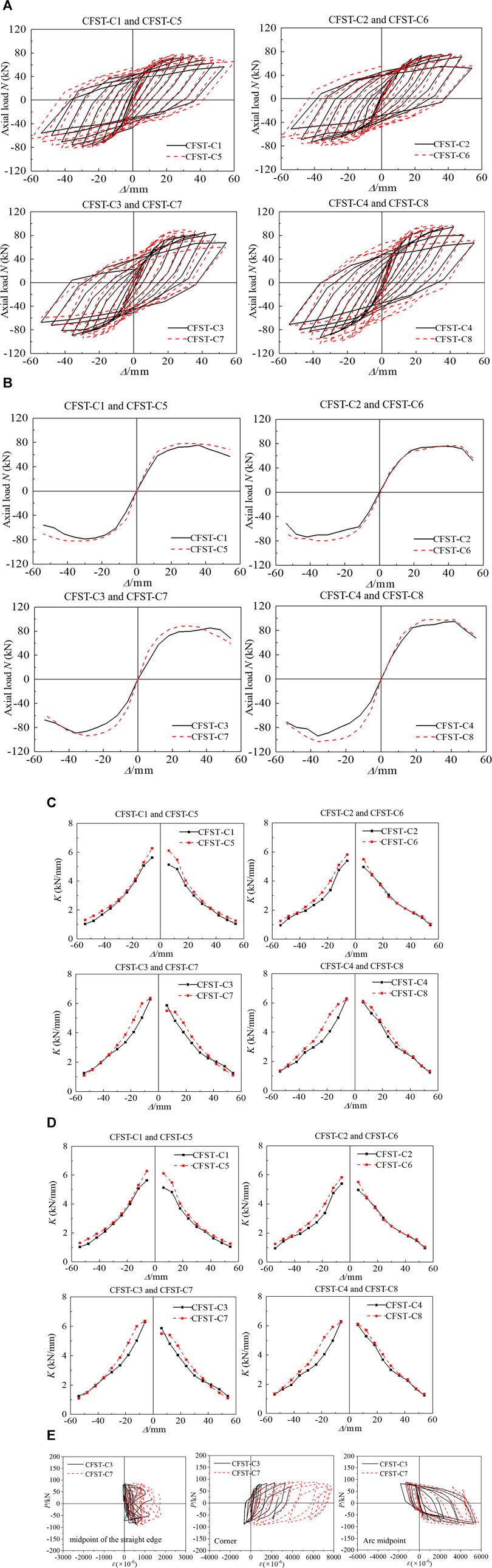
FIGURE 13. Effect of axial compression ratio on seismic property. (A) Hysteresis curve. (B) Skeletal curve. (C) Stiffness degradation. (D) Energy absorption. (E) Hoop strain.
The width–thickness ratios of specimens CFST-C1–CFST-C4 and CFST-C9–CFST-C12 are 2:1 and 3:1, respectively. Given the inconsistency in the height of specimens, the bending moment at the bottom of specimens is compared. Figure 14 shows the effect of the width–thickness ratio on the ultimate bending moment. The bearing capacity of CFST-C9–CFST-C12 is 75.9%, 75.4%, 79.9%, and 83.8% higher than that of CFST-C1–CFST-C4, respectively. The section width–thickness ratio considerably affects the bearing capacity of the specimen.
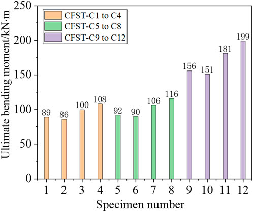
FIGURE 14. Comparisons of ultimate bending moment.
Figure 15 shows the effect of the width–thickness ratio on hoop strain. The results show that under low cyclic load, the surface transverse deformation coefficient of model CFST-C1 steel tube in the midpoint of the straight edge is greater than that of model CFST-C9, indicating that the larger the aspect ratio, the weaker the constraining effect of steel tube on concrete. Under different aspect ratios, the load–circumferential strain curves of steel tubes at each point of the model show certain hysteresis.
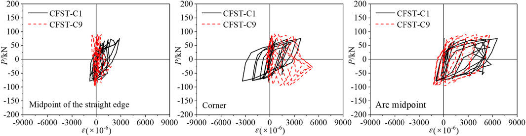
FIGURE 15. Effect of width-thickness ratio on hoop strain.
This study investigates the seismic behavior of a CFST column with a multichamber round-ended cross-section. A total of 12 composite columns were included in the experiments, and the investigated parameters included chamber layout, axial compression ratio, and section width–thickness ratio. From this study, the following conclusions can be drawn:
(1) The CFST columns with a multichamber round-ended cross-section exhibit excellent seismic performance under pseudostatic load, and the skeleton curves remain horizontal or show a weak decline section in the late loading period. The specimen showed bending shear failure, and no pinch phenomenon was observed.
(2) The more chambers arranged, the fuller the hysteresis curve and the higher the horizontal bearing capacity. The stiffness degradation trend of all specimens decreases with an increase in the number of cycles. The displacement ductility coefficient of all specimens ranges from 3.88 to 7.44, which meets the seismic design requirements.
(3) The more chambers the specimen has, the greater the energy dissipation. This relationship reflects the influence of chamber layout on structural energy dissipation. Compared with the single-cavity column, the energy dissipation of the three-cavity, and four-cavity columns were larger by 5.9%, and 11.6%, respectively. The higher the axial compression ratio, the larger the energy dissipation. The energy dissipation of CFST-C5–CFST-C8 is 18.2% larger than that of CFST-C1–CFST-C4.
(4) Based on the test results, for multicavity confined circular CFST columns with a large length–width ratio, the chamber arrangement should bring the long and short sides closer together.
The original contributions presented in the study are included in the article/Supplementary material, further inquiries can be directed to the corresponding author.
JL: Formal Analysis, Funding acquisition, Investigation, Methodology, Project administration, Supervision, Validation, Visualization, Writing–original draft, Writing–review and editing. WY: Data curation, Validation, Visualization, Writing–original draft. YF: Writing–review and editing. ZP: Data curation, Validation, Visualization, Writing–original draft.
The author(s) declare financial support was received for the research, authorship, and/or publication of this article. This research is financially supported by the National Natural Science Foundation of China (Grant No. 52008159), Hunan Education Department Foundation Funded Project (Grant No. 21A0504), Natural Science Foundation of Hunan Province (Grant No. 2022JJ30112), Aid program for Science and Technology Innovative Research Team in Higher Educational Institutions of Hunan Province.
The authors declare that the research was conducted in the absence of any commercial or financial relationships that could be construed as a potential conflict of interest.
All claims expressed in this article are solely those of the authors and do not necessarily represent those of their affiliated organizations, or those of the publisher, the editors and the reviewers. Any product that may be evaluated in this article, or claim that may be made by its manufacturer, is not guaranteed or endorsed by the publisher.
Alatshan, F., Osman, S. A., Hamid, R., and Mashiri, F. (2020). Stiffened concrete-filled steel tubes: a systematic review. Thin-walled Struct. 148 (3), 106590. doi:10.1016/j.tws.2019.106590
Chen, H. R., Wang, L., Chen, H. T., and Cui, W. (2021). Experimental study on the seismic behavior of prefabricated L-shaped concrete-filled steel tube with rectangular multi-cell columns under different lateral loading directions. J. Constr. Steel Res. 177 (8), 106480. doi:10.1016/j.jcsr.2020.106480
Ding, F. X., Fu, L., Liu, X. M., and Liu, J. (2016). Mechanical performances of track-shaped rebar stiffened concrete-filled steel tubular (SCFRT) stub columns under axial compression. Thin-Walled Struct. 99 (2), 168–181. doi:10.1016/j.tws.2015.11.022
Ding, F. X., Liu, J., Liu, X. M., Zhi-wu, Y., and Yong-suo, L. (2018). Experimental investigation on hysteretic behavior of simply supported steel-concrete composite beam. J. Constr. Steel Res. 144 (5), 153–165. doi:10.1016/j.jcsr.2018.01.018
Fei, L., Goto, Y., Kawanishi, N., and Xu, Y. (2020). Three-dimensional numerical model for seismic analysis of bridge systems with multiple thin-walled partially concrete-filled steel tubular columns. J. Struct. Eng. 146 (1), 04019164. doi:10.1061/(asce)st.1943-541x.0002451
GJ101-2015 (2015). Code for seismic test method of building. Beijing, China: China Building Industry Press.
Hassanein, M. F., and Patel, V. I. (2018). Round-ended rectangular concrete-filled steel tubular short columns: FE investigation under axial compression. J. Constr. Steel Res. 140 (1), 222–236. doi:10.1016/j.jcsr.2017.10.030
Hu, R., Fang, Z., Benmokrane, B., and Xu, B. D. (2022a). Experimental behavior of UHPC shear walls with hybrid reinforcement of CFRP and steel bars under lateral cyclic load. J. Compsites Constr. 26 (2), 04022011. doi:10.1061/(asce)cc.1943-5614.0001203
Hu, R., Fang, Z., and Xu, B. D. (2022b). Cyclic behavior of ultra-high-performance concrete shear walls with different axial-load ratios. ACI Struct. J. 119 (2), 233–246. doi:10.14359/51734339
Qiao, Q. Y., Li, X. Y., Cao, W. L., and Dong, H. (2018). Seismic behavior of specially shaped concrete-filled steel tube columns with multiple cavities. Struct. Des. Tall Build. 27 (12), 1–15. doi:10.1002/tal.1485
Ren, Z. G., Wang, D. D., and Li, P. P. (2022). Axial compressive behaviour and confinement effect of round-ended rectangular CFST with different central angles. Compos. Struct. 285, 115193. doi:10.1016/j.compstruct.2022.115193
Shen, Q. H., Wang, F. Q., Wang, J. F., and Ma, X. (2022). Cyclic behaviour and design of cold-formed round-ended concrete-filled steel tube columns. J. Constr. Steel Res. 190, 107089. doi:10.1016/j.jcsr.2021.107089
Shen, Q. H., Wang, J. F., Liew, R., Gao, B., and Xiao, Q. (2020). Experimental study and strength evaluation of axially loaded welded tubular joints with round-ended oval hollow sections. Thin-Walled Struct. 154, 106846. doi:10.1016/j.tws.2020.106846
Wang, J. F., and Shen, Q. H. (2023). Numerical analysis and design of thin-walled RECFST stub columns under axial compression. Thin-Walled Struct. 129, 166–182. doi:10.1016/j.tws.2018.03.024
Wang, K. H. (2015). Seismic research of bridge. Beijing, China: China Railway Publishing House. (in Chinese).
Wu, H. P., Cao, W. L., Qiao, Q. Y., and Dong, H. (2016). Uniaxial compressive constitutive relationship of concrete confined by special-shaped steel tube coupled with multiple cavities. Materials 86 (9), 86–19. doi:10.3390/ma9020086
Wu, H. P., Qiao, Q. Y., Cao, W. L., Dong, H., and Zhang, J. (2017). Axial compressive behavior of special-shaped concrete filled tube mega column coupled with multiple cavities. Steel and Compos. Struct. 23 (6), 633–646. doi:10.12989/scs.2017.23.6.633
Yin, F., Xue, S. D., Cao, W. L., Dong, H. Y., and Wu, H. P. (2020). Experimental and analytical study of seismic behavior of special-shaped multicell composite concrete-filled steel tube columns. J. Struct. Eng. 146 (1), 04019170. doi:10.1061/(asce)st.1943-541x.0002442
Zhang, Q., and FuXu, L. L. (2020). An efficient approach for numerical simulation of concrete-filled round-ended steel tubes. J. Constr. Steel Res. 170, 106086. doi:10.1016/j.jcsr.2020.106086
Zhou, Z., Denavit, M. D., and Zhou, X. H. (2023). New cross-sectional slenderness limits for stiffened rectangular concrete-filled steel tubes. Eng. Struct. 280, 115689. doi:10.1016/j.engstruct.2023.115689
Zhou, Z., Gan, D., Denavit, M. D., and Zhou, X. H. (2022). Seismic performance of square concrete-filled steel tubular columns with diagonal binding ribs. J. Constr. Steel Res. 189, 107074. doi:10.1016/j.jcsr.2021.107074
Keywords: concrete-filled steel tubular column, round-ended section, hysteretic behavior, multichamber restraint, ductility, stiffness degradation
Citation: Liu J, Yu W, Fang Y and Pan Z (2024) Experimental study on the seismic performance of concrete-filled steel tube columns with a multiple-chamber round-ended cross-section. Front. Mater. 11:1363206. doi: 10.3389/fmats.2024.1363206
Received: 30 December 2023; Accepted: 31 January 2024;
Published: 22 February 2024.
Edited by:
Biao Hu, Shenzhen University, ChinaCopyright © 2024 Liu, Yu, Fang and Pan. This is an open-access article distributed under the terms of the Creative Commons Attribution License (CC BY). The use, distribution or reproduction in other forums is permitted, provided the original author(s) and the copyright owner(s) are credited and that the original publication in this journal is cited, in accordance with accepted academic practice. No use, distribution or reproduction is permitted which does not comply with these terms.
*Correspondence: Yawei Fang, ZmFuZ3lhd2VpQGhudS5lZHUuY24=
Disclaimer: All claims expressed in this article are solely those of the authors and do not necessarily represent those of their affiliated organizations, or those of the publisher, the editors and the reviewers. Any product that may be evaluated in this article or claim that may be made by its manufacturer is not guaranteed or endorsed by the publisher.
Research integrity at Frontiers
Learn more about the work of our research integrity team to safeguard the quality of each article we publish.