- 1Department of Bridge Engineering, College of Civil Engineering, Tongji University, Shanghai, China
- 2Department of Civil, Environmental and Architectural Engineering, University of Kansas, Lawrence, KS, United States
- 3Institute of Mountain Hazards and Environment Chinese Academy of Sciences, Chengdu, China
- 4Department of Civil Engineering, Sir Syed University of Engineering and Technology, Karachi, Pakistan
- 5Department of Civil Engineering, Collage of Engineering, Jazan University, Jazan, Saudi Arabia
- 6Department of Civil Engineering, National Institute of Technology, Calicut, Kerala, India
- 7University of Engineering and Technology Taxila, Taxila, Pakistan
The limitations in the available reinforcing methods have accompanied the increasing popularity of 3D Concrete Printing (3DCP). Incorporating steel fibers as reinforcement is a promising approach to overcome these limitations. However, the impact of the printing process on the alignment of these fibers is not well understood. Therefore, the objective of this research is to quantitatively analyze the distribution of steel fiber alignment in 3D printed concrete. To achieve this, digital image analysis was employed to assess the influence of nozzle diameter, print speed, and fiber content on fiber alignment in both mold-cast and 3D-printed samples. UHPC matrix without fiber addition and fiber reinforced UHPC composites with brass-coated steel fiber contents of 1.5% and 3% by volume fraction were printed. Furthermore, Material nozzles ranging from 10 mm to 40 mm in size were employed and printing speeds of 15, 25, 35, and 45 mm/s were adjusted. Subsequently, the study examined the implications of fiber alignment on the hardened performance of printed specimens and compared them with conventionally mold-cast samples. The findings of the study demonstrated that increasing the fiber content and using smaller diameter nozzles during the printing procedure led to significant improvements in fiber orientation along the printing direction. As a result, the mechanical performance of the printed samples showed a substantial enhancement compared to the specimens produced through mold casting, primarily due to the improved fiber alignment.
1 Introduction
The 3D Concrete Printing (3DCP) is an innovative technique in additive manufacturing, characterized by the automated construction of structures through the sequential deposition of cementitious materials. This state-of-the-art technology has been extensively studied in recent years (Warszawski and Navon, 1998; Rahul et al., 2019; Liu and Sun, 2021; Yekai et al., 2022), fundamentally revolutionizing the design, delivery, and construction of structures by leveraging advancements in building automation and 3DCP methodologies. By utilizing digital fabrication methods and concrete materials, 3DCP has the potential to achieve significant reductions in construction waste by 30%–60%, substantial decreases in construction time by 50%–70%, and substantial decreases in labor costs by 50%–80% (Khoshnevis, 2004; Hamidi and Aslani, 2019; Rahul et al., 2019; Zhang et al., 2019; Miao et al., 2020). Furthermore, this groundbreaking technology demonstrates modeless manufacturing, enabling rapid and seamless construction while promoting energy conservation and environmental preservation. Moreover, it provides architects and structural designers with an opportunity to enhance their creative freedom and explore innovative materials, modern systems, and upgraded structures (Khoshnevis, 2004; Zhang et al., 2019; Miao et al., 2020). However, the widespread adoption of this technology is hindered by the limited availability of printable concretes and the complex challenges associated with reinforcement, in contrast to traditional construction methods and reinforcement techniques.
To address the aforementioned challenges, previous scholarly investigations have devised and employed various types of fiber-reinforced ultra-high-performance concretes (UHPC) that are compatible with the technology of 3D printing (Buswell et al., 2007a; Martinez et al., 2008; Lim et al., 2012; Shahzad et al., 2020a; Shahzad et al., 2021a; Yekai et al., 2022; Paruthi et al., 2023a; Paruthi et al., 2023b; Neupane et al., 2023). These materials were specifically engineered to possess compressive strengths surpassing 150 MPa and moduli of rupture exceeding 30 MPa. Published literature suggests that these fiber-reinforced UHPCs can partially replace conventional reinforcement (Buswell et al., 2007a; Lim et al., 2012; Shahzad et al., 2020a; Shahzad et al., 2021a; Paruthi et al., 2023b). The flexural strength values of the printed specimens exhibited higher values in the horizontal plane of the printing direction when compared to the conventionally mold-cast samples. This discrepancy can be attributed to the distinct arrangement of fibers that is preferred in the printed specimens, as opposed to the random alignment of fibers in the mold-cast samples (Paruthi et al., 2023c). Previous investigations (Le et al., 2012; Amin et al., 2017) have demonstrated that the inclusion of short steel fibers can enhance both crack propagation resistance and load-bearing capacity in mold-cast specimens. To manipulate and modify the alignment of fibers in such specimens, various factors, such as the mixing procedure and placement methods, can be employed (Khoshnevis, 2004; Buswell et al., 2007b; Wijffels et al., 2017; Pérez and Medina, 2018; Suiker, 2018; Jagadesh et al., 2023). Previous studies have indicated that achieving fiber orientation aligned with the 3D printing direction can be accomplished through the application of mechanical pressure and extrusion force (Panda et al., 2019; Kruger et al., 2020).
Recent explorations have specifically examined the behavior of short steel/polymeric fibers, which have been observed to align themselves parallel to the direction of printing (Ogura et al., 2018; Meshram et al., 2023). For example, research findings indicate that 3D printed polyethylene (PE) fiber-reinforced specimens demonstrate enhanced tensile properties when compared to mold-cast samples (Meshram et al., 2023). Nonetheless, Figueiredo (Figueiredo et al., 2020) observed that the alignment of PVA (Polyvinyl alcohol) fibers used as reinforcement in the printed samples exhibited a preference towards the printing direction. Limited research has been conducted on the influence of various factors, including nozzle diameter, printing speed, rheological behavior of the concrete, and fiber characteristics (such as length and type), on the distribution of fiber alignment in 3D printed UHPC. Further investigation is necessary to comprehensively understand the parameters that affect fiber alignment distribution and their subsequent impacts on the hardened performance of 3D printed UHPC. Therefore, the objective of this ongoing research project is to extensively examine the existing literature and undertake a comprehensive study to gain deeper insights into this subject matter.
The present study carried out a series of experiments to analyze the distribution of fiber alignment in additively manufactured fiber-reinforced UHPC. Subsequently, the investigation analyzed the influence of fiber content, printing speed, and nozzle diameter on the distribution of fiber alignment. Moreover, the research conducted an examination on the impact of fiber alignment on stress-deflection responses in specimens produced through casting and additive manufacturing techniques. The distribution of fiber alignment, relative to the printing direction, was determined by employing image processing software. Multiple mold-cast and printed samples were prepared and subsequently, their mechanical performance was compared.
2 Materials and methods
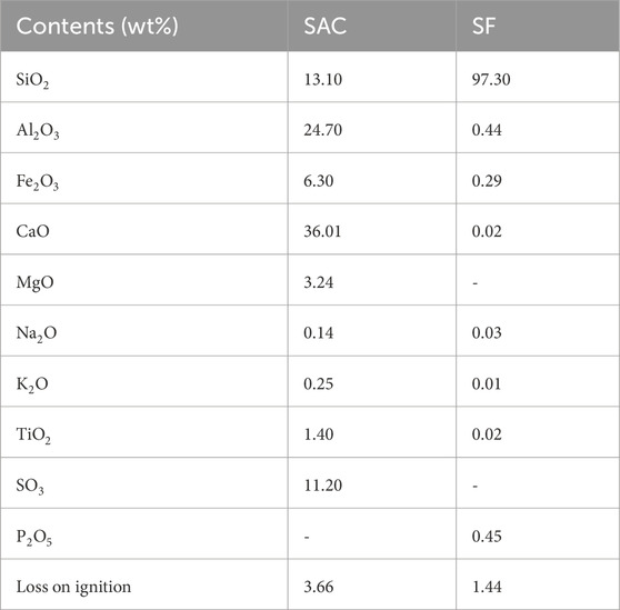
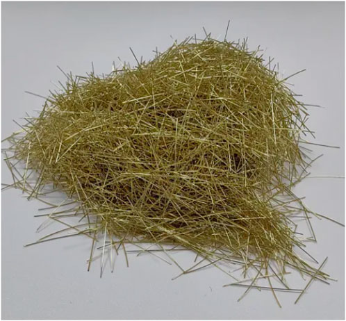
The study utilized ASTM C150/C150M compliant binders, namely, Sulfo-aluminate cement (SAC) and silica fume (SF) (ASTM, 2020). The chemical composition of these binders is presented in Table 1. Silica sand was employed as an aggregate, with fine, medium, and coarse grades selected based on different sieve size gradations. This choice enabled a broader range of particle size distribution. Figure 1 displays the particle size distribution curves of the binder materials and silica sands employed in the investigation. Figure 2 presents the brass coated steel fibers used in this study. Table 2 displays the mixture proportions for fiber reinforced UHPC suitable for 3D printing. Admixtures, specifically a nano-clay-based Viscosity Modifying Agent (VMA) and a Polycarboxylate ether-based Water Reducing Agent (WRA), both adhering to the standards of ASTM C33/C33M-18 (ASTM, 2018), were incorporated. The steel microfibers employed in the study were straight, measuring 8 mm in length, and possessed an aspect ratio of 50. These particular fibers underwent a brass coating process, and detailed information regarding their overall properties and attributes can be found in Table 3.
3 Experimental details
3.1 Mixture preparation
The mixing procedure in this study adhered to a standardized protocol. Initially, the dry materials, which included binders and aggregates (SAC, SF, and sands), were mixed uniformly for a duration of 3 min using an 80-L capacity pan mixer to ensure complete homogeneity. Subsequently, approximately 80% of the total water volume was gradually added and stirred for a period of 5 min. Following this, the liquid form of HRWRA was introduced into the remaining water and blended according to the recommended specifications outlined by Willie et al. (Wille et al., 2011), as per the research protocol. To ensure the proper composition of the mixture, the aforementioned step was performed. Continuous mixing was employed to achieve the desired rheology of the mixture. In the case of the reinforced mixtures, brass-coated fibers were gradually added over a duration of 5 min, while the mixing pan was repositioned to ensure even dispersion of the fibers. Subsequently, a visual examination was carried out to evaluate the dispersion of the fibers. Lastly, a VMA (Viscosity Modifying Agent) was included to enhance the printing characteristics of the mixture.
3.2 Additive manufacturing method
The utilization of a 3D printer with a steel frame gantry and three degrees of freedom facilitated the execution of the printing process. The printer’s observable region, as depicted in Figure 3, possesses measurements of 1.8 m in length, 1.6 m in width, and 1.8 m in height, thereby providing an efficient workspace. To ensure meticulous and controlled nozzle motion, a customized computer program was employed to regulate the tri-axial movement of the nozzle within the designated workspace.
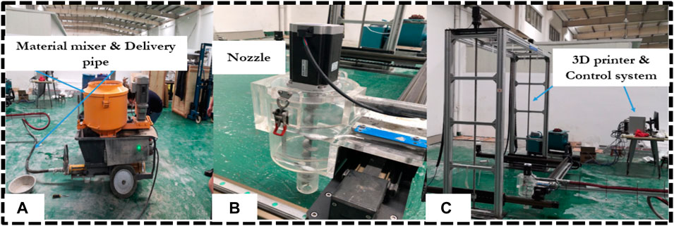
FIGURE 3. 3D printing system (A) Mixing and feeding system (B) Nozzle assembly (C) 3D printer and control system (Shahzad et al., 2020a).3D-printed fiber reinforced UHPC specimen.
Furthermore, a detachable circular orifice was implemented at the bottom outlet of the extruder. The printing system employed in this study is visually represented in Figure 4.
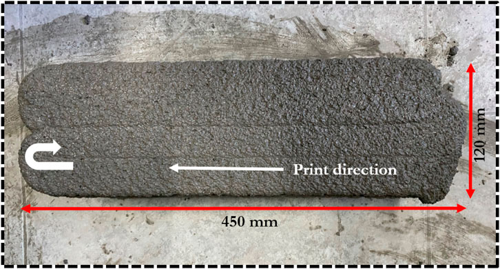
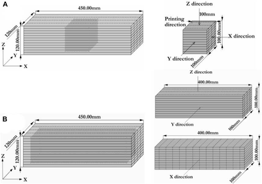
To adhere to the testing requirements for compressive and flexural strength, samples with dimensions of 120 mm × 120 mm x 450 mm were additively manufactured and subsequently sectioned. These samples consisted of 12 layers, each measuring 10 mm in thickness, and were 3D printed with precise control over the width of each layer by adjusting the extrusion rate at different print speeds, considering the size of the nozzle. Subsequent to the completion of each layer, the printer was programmed to elevate the nozzle by 10 mm, corresponding to the height of the layer. An illustration of the printed specimen is presented in Figure 3. In order to examine the impact of fiber content, extruder diameter, and printing speed on fiber alignment in 3D printed fiber reinforced UHPC specimens, a series of twenty sets of specimens were produced using three distinct printing schemes denoted as A, B, and C. Each scheme was devised with specific parameter variations to enable the analysis of their respective effects on fiber alignment. The objective of this research endeavor was to enrich comprehension pertaining to the interplay between printing parameters and fiber alignment in 3D printed fiber reinforced UHPC specimens.
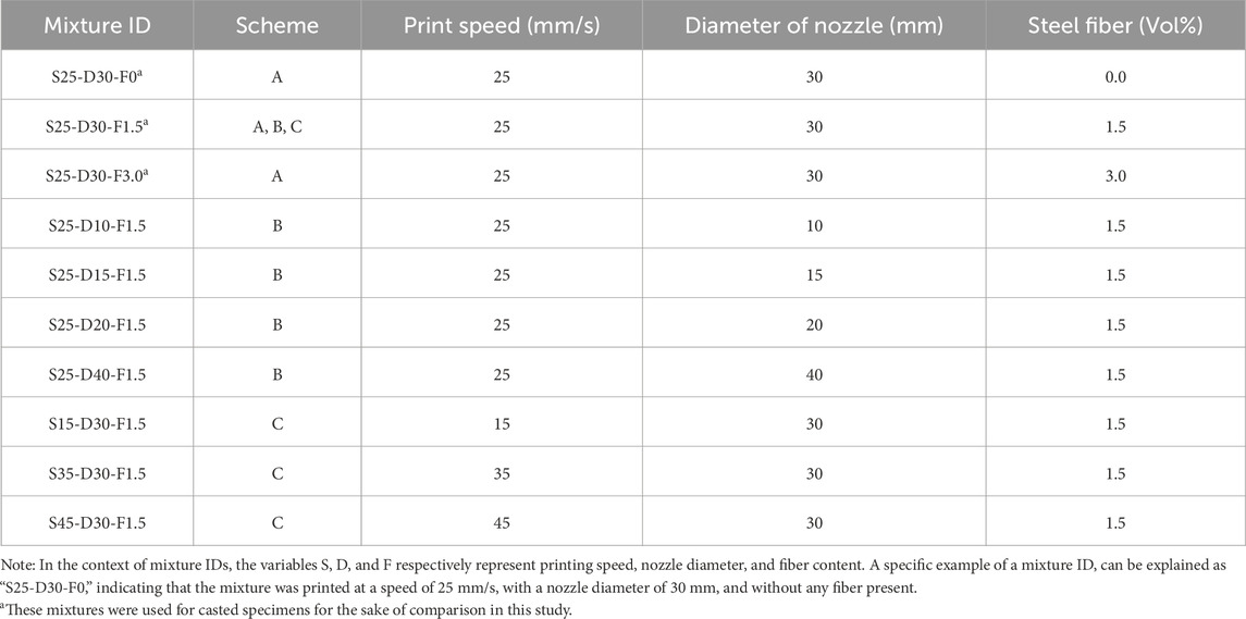
Scheme-A: UHPC matrix without fiber addition and fiber reinforced UHPC composites with brass-coated steel fiber contents of 1.5% and 3% by volume fraction were printed at a speed of 30 mm/s and an annular nozzle size of 30 mm. Scheme-B: The UHPC samples were 3D-printed utilizing a steel fiber volume fraction of 1.5% at a speed of 30 mm/s. Material nozzles ranging from 10 mm to 40 mm in size were employed in scheme B. Scheme-C: Printing speeds of 15, 25, 35, and 45 mm/s were adjusted and the specimens were printed with steel fibers accounting for 1.5% of the contents, utilizing an annular nozzle with a diameter of 30 mm.
Table 4 provides details concerning print speeds, nozzle diameters, mixture schemes, and IDs. The alterations in nozzle diameters and print speeds resulted in fluctuations in flow rate at the nozzle orifice during the printing process, employing schemes-B and C. To assess the performance of specimens in flexure and compression, 100 mm cubic molds and 100 mm × 100 mm x 400 mm prismatic conventional molds were utilized, casting them through scheme-A.
3.3 Curing
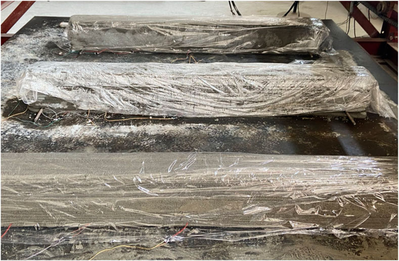
In this investigation, the curing procedure recommended in reference (Association Francaise de G’ enie Civil AFGC, 2002) was employed. Following the completion of the printing process, the printed specimens were enveloped with moist plastic sheets and left at the surrounding temperature (25 ± 3 C) for a duration of 48 h as shown in Figure 5. Printed concrete cured at 12°C and 20°C achieved similar strength values at the age of 2 years (about 130 MPa), while printed concrete made at 25°C achieved this strength much faster. It can therefore be concluded that a temperature of 25°C (ambient) is the most favorable, due to the increase in strength over time. Similarly, the mold-cast specimens were taken out from their molds after 24 h and allowed to undergo curing at ambient temperature for an additional 24 h. Subsequently, after a 7-day curing period, the printed samples were sawn into various sizes to conduct compressive and flexural property testing. Notably, the researchers observed that the compressive strength remained largely unchanged even with extended curing for a period of 28 days. This finding is consistent with previous studies documented elsewhere (Bosco and Salet, 2019).
3.4 Tests for hardened properties
After the 7-day curing period, the printed specimens underwent a sawing process to obtain 100 mm cubes for compressive strength testing and 100 mm × 100 mm x 400 mm prismatic samples for flexural strength testing. ASTM C39 and ASTM C78 standards were used for compression and flexural testing of printed specimens, respectively. Before conducting the tests, all sawn samples were flattened on their contact sides. In order to investigate the flexural behavior of the 3D printed concrete, a flexural load was systematically applied using a displacement control approach at a rate of 1 mm/min. To evaluate the anisotropic characteristics of the material, cut specimens were subjected to compression and flexure tests in three different loading directions, as depicted in Figure 6. To ensure reliability and accuracy, the compression and flexure tests were conducted on a minimum of three samples for each loading direction, and the obtained results were subsequently averaged. Similarly, the same loading protocol was employed during the compression and flexure behavior testing of the mold-cast samples to maintain consistency and enable direct comparisons with the 3D printed samples.
3.5 Fiber orientation
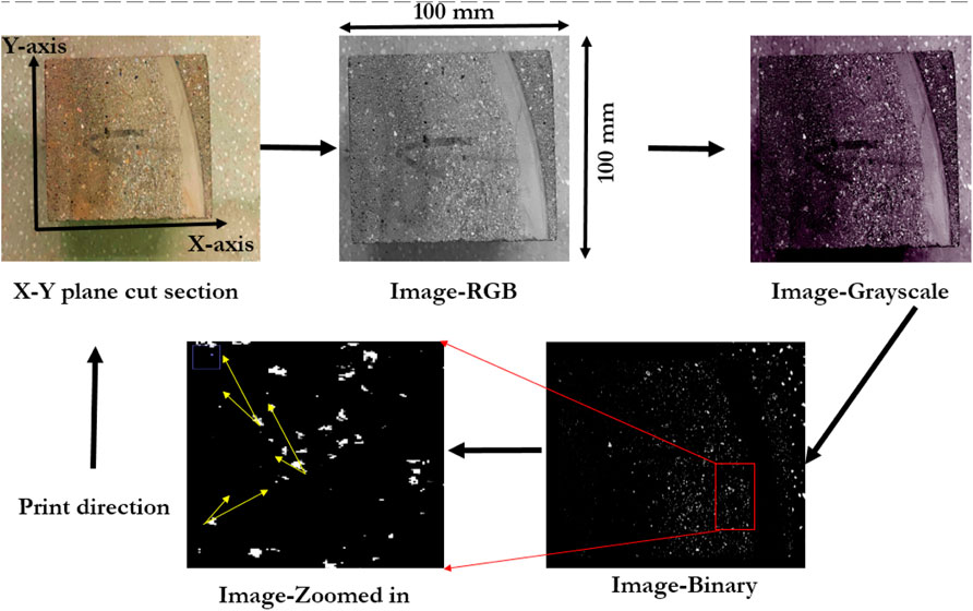
The available literature demonstrates the successful application of various techniques to evaluate the orientation of different fibers in concrete. These methods encompass direct methodologies like X-ray scanning, digital image analysis, scanning electron microscopy analysis, computed tomography scanning, and manual fiber counting in a cross-section of the sample. Extensive explanations of these techniques are available in sources (Association Francaise de G’ enie Civil AFGC, 2002; Alam et al., 2022; Vermeer and Borst, 1984; Qamar and Li, 2023; Alfani and Guerrini, 2005; Roussel, 2006; Paruthi et al., 2022; Nerella and Mechtcherine, 2019; Saba et al., 2021). Furthermore, for a more in-depth analysis of fiber orientation and finer details, the utilization of image processing techniques alongside computed tomography scanning has demonstrated its efficacy (Ma et al., 2019). Thus, this study utilized the image processing method illustrated in Figure 5 to investigate fiber alignment. ASTM E2533 standard method was applied which provides guidelines for the measurement of geometric properties of objects using digital image analysis.
To analyze the orientation of fibers in the printed samples, three 100 mm cubes were obtained and cut into thin sections of 20 mm along the X-Y planes. A similar process was carried out on mold-cast samples for comparative analysis, as depicted in Figure 7. Afterward, the cut sections underwent thorough smoothing and flattening using fine grit sandpapers to prepare them for image analysis. High-resolution RGB images of the sections were captured using a photo scanner and then transformed into grayscale and binary images. The identification of steel fibers involved fine-tuning the intensity threshold against a black background and filtering out other objects based on specific criteria to achieve precise results and parameters. To ensure precision, the orientation of each fiber was computed relative to the printing direction (X-axis). These measurements were obtained from binary images, ensuring accuracy. Probability-based methods were employed for angle measurement during the image processing, and the results are detailed in the discussion section. Earlier studies have examined similar aspects in cast-mold specimens, as noted in prior research (Huang et al., 2018; Ma et al., 2018; Shahzad et al., 2020b). Eq. 1 presented below enables the computation of the mean value for fiber alignment.
The parameter
4 Results and discussion
4.1 Compressive strength
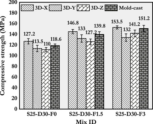
The compressive strength results of fiber-reinforced UHPC samples, prepared using both 3D printing and casting methods, and with different fiber quantities, are illustrated in Figure 8. The inclusion of fibers has significantly enhanced the compressive strength of both the 3D printed and mold-cast samples. For 3D printed specimens, the loading orientation was found to have a more substantial influence on the compressive strength of printed concrete compared to the fiber content. In Figure 8, it is evident that the application of loading in the X-direction yielded the highest compressive strength in all cases. This phenomenon can be attributed to the combined effect of the gravitational force exerted on the printed layers and the pressure of extrusion during the printing process (Asprone et al., 2018). In contrast, the compressive strength exhibited a decrease of up to 15% in both the Y and Z directions when compared to the X-direction. This anisotropic behavior has been documented in various forms of printed concrete, as reported in previous studies (Shahzad et al., 2021b; Shahzad et al., 2023).
The compressive strength of the mold-cast specimens was observed to be higher than the Y and Z directions of the printed specimens, while slightly lower than the X-direction of the printed specimens. The compressive strength of both the printed and mold-cast specimens ranged from 120 to 155 MPa in all directions, with different fiber contents ranging from 0% to 3%.
4.2 Fracture strength
4.2.1 Scheme A: Influence of fiber contents
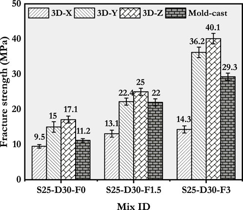
The fracture strengths of specimens fabricated through casting and printing were assessed at various fiber contents, and the results are depicted in Figure 9. Both mold-cast and printed specimens exhibited anisotropic characteristics in their fracture strength, resembling the observed behavior in their compressive strength. The upper limit of flexural strength recorded in printed samples during testing, which is 40.1 MPa in the Z-direction. This is associated with the Mix ID S25-D30-F3.
Moreover, the strength of the printed samples significantly differed depending on the loading direction. Specifically, specimens loaded in the Z and Y directions demonstrated higher strength compared to those loaded in the X direction. The alignment of fibers in the X direction during printing is responsible for the observed effect. When subjected to three-point bending loads, the printed samples experienced the highest tensile stresses on the middle bottom face. This outcome can be related to the parallel orientation of fibers along the span direction, which impeded crack propagation. Conversely, the samples loaded in the X-direction exhibited relatively lower fracture strength due to the existence of flexural crack planes parallel to the fibers, resulting in no significant impact. The behavior of specimens printed without fiber content demonstrated a similar pattern.
In the analysis of samples along the X-direction, it was noted that the fracture strengths of 3D-Z samples surpassed those of 3D-Y samples. This variation in strength can be attributed to the consolidation of layers at the lower portion of the specimens due to the imposition of dead and live loads from consecutive printed layers. Specifically, the 3D-Z specimens exhibited fracture strengths that were up to 40% greater compared to the specimens prepared through casting incorporating 3% fiber content. The dissimilarity in fiber alignment between the printed and mold-cast specimens could potentially explain this disparity.
4.2.2 Scheme B: Influence of nozzle diameter
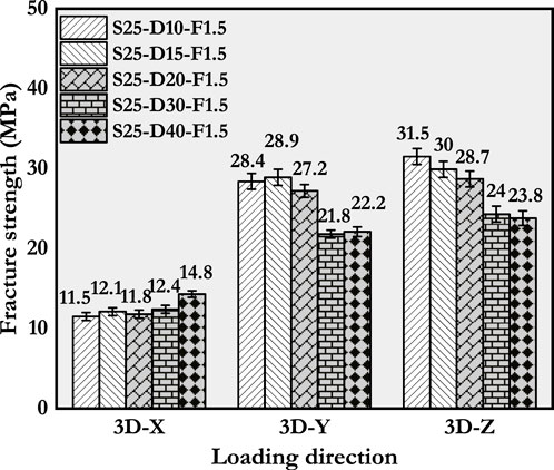
Figure 10 illustrates the fracture strength outcomes acquired from printed samples employing different nozzle diameters. The modification of nozzle diameters from 10 mm to 40 mm had a notable impact on fiber alignment, resulting in significant variations in the fracture strength values between 3D-Z and 3D-Y specimens. When compared to the fracture strength values of S25-D40-F1.5 printed specimens, S25-D10-F1.5 printed specimens exhibited an increase of up to 30%. The fracture strength values of the printed specimens, utilizing nozzle diameters of 30 mm and 40 mm, were determined to be comparable. This similarity can be attributed to the existence of a critical ratio between fiber length and nozzle diameter. Beyond this critical ratio, the alignment of fibers in the printing material remains unaffected by the nozzle diameters.
4.2.3 Scheme C: Influence of print speed
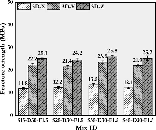
Figure 11 presents the results of fracture strength tests performed on 3D printed samples at different print speeds. The findings suggest that there is no statistically significant difference in the fracture strength values among the printed specimens at various print speeds. Therefore, it can be deduced that the alignment of fibers in the printed specimens is not noticeably affected by the print speeds.
4.3 Stress-deflection response under flexure
4.3.1 Scheme A: Influence of fiber contents
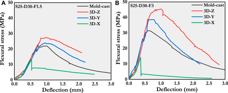
The stress-deflection responses of printed and mold-cast specimens with different fiber contents (1.5% and 3%) under flexural loads are depicted in Figure 12. The printed specimens were assessed in the Y and Z directions, and their failure behavior was analyzed using deflection-hardening (DH). The results confirmed the presence of fiber orientation perpendicular to the printing direction (X direction), as indicated by the observed DH behavior in the printed samples. In contrast, the 3D-X printed specimens did not display deflection-hardening behavior. This emphasizes the importance of fiber content and orientation in determining the mechanical performance of printed materials. Furthermore, the findings from the research demonstrate that the implementation of the 3D-X printing technique with a 1.5% fiber inclusion led to specimens exhibiting elevated residual strengths following the attainment of the maximum load, in contrast to those with a 3% fiber inclusion. It is important to highlight that the emergence of premature failure cracks was attributed to vulnerable interlayer connections, ultimately resulting in energy dissipation due to fracture. These cracks propagated within the material’s structure towards the location of the applied load, thereby yielding a residual strength beyond the peak point.
The observed reduction in strength following the inclusion of 3% fiber can be related to the heightened orientation of fibers within the plane parallel to the direction of the print. In contrast, mold-cast samples containing 1.5% fiber demonstrated a slightly inferior ductile hardening behavior compared to those cast with 3% fiber. Conventionally cast specimens displayed a more random fiber alignment than the printed samples, consequently leading to a diminished flexural response. These findings bear significant implications in the selection of fabrication methods for fiber-reinforced composites. Furthermore, this study underscores the critical importance of comprehending the impact of fiber orientation on material behavior.
4.3.2 Scheme B: Influence of nozzle diameter
Figure 13 presents the stress-deflection response curves of specimens fabricated with a 1.5% fiber content and varying nozzle diameters. The findings demonstrate that the specimens printed in the Y and Z directions exhibited negligible deformation-hardening (DH) behavior. Conversely, the behavior of the specimens printed in the X direction differed depending on the nozzle diameter, displaying either deflection-softening (DS) or brittle characteristics.
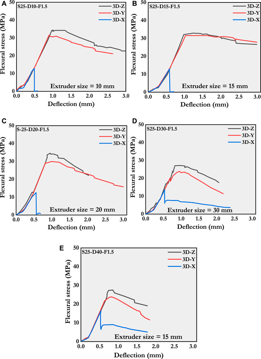
FIGURE 13. Deflection responses under flexural stress of printed specimens with different sizes of extruders. (A) 10 mm, (B) 15 mm, (C) 20 mm, (D) 30 mm, and (E) 40 mm.
After examining the printed specimens, it was observed that employing nozzle diameters of 20 mm or smaller led to brittle behavior in the 3D-X specimens. Conversely, when nozzle diameters of 30 mm or 40 mm were used during the extrusion process, the printed specimens exhibited ductile behavior. These observations suggest that reducing the nozzle size can result in favorable fiber orientation along the printing direction. The stress-deflection response curves of samples printed with nozzle diameters of 30 mm and 40 mm exhibited similar trends, unaffected by the direction of applied loads. Consequently, it can be inferred that as the nozzle diameter of the printed specimen exceeds 20 mm, the influence of nozzle size on fiber alignment diminishes. It is important to note that these findings are relevant for preventing brittle or DS behavior in 3D printing and can aid in achieving optimal fiber alignment.
4.3.3 Scheme C: Influence of print speed
Figure 14 illustrates the stress-deflection response curves for specimens printed at varying print speeds. It is evident from schemes A and B that specimens printed in the 3D-Y and 3D-Z directions, aligned with the printing direction, and exhibited DH behavior. Conversely, specimens loaded in the 3D-X direction, perpendicular to the printing direction, displayed DS behavior. Notably, the stress-deflection response curves demonstrated striking similarity across specimens printed at different speeds. Therefore, the data suggests that print speed has a negligible impact on the stress-deflection response of the printed specimens.
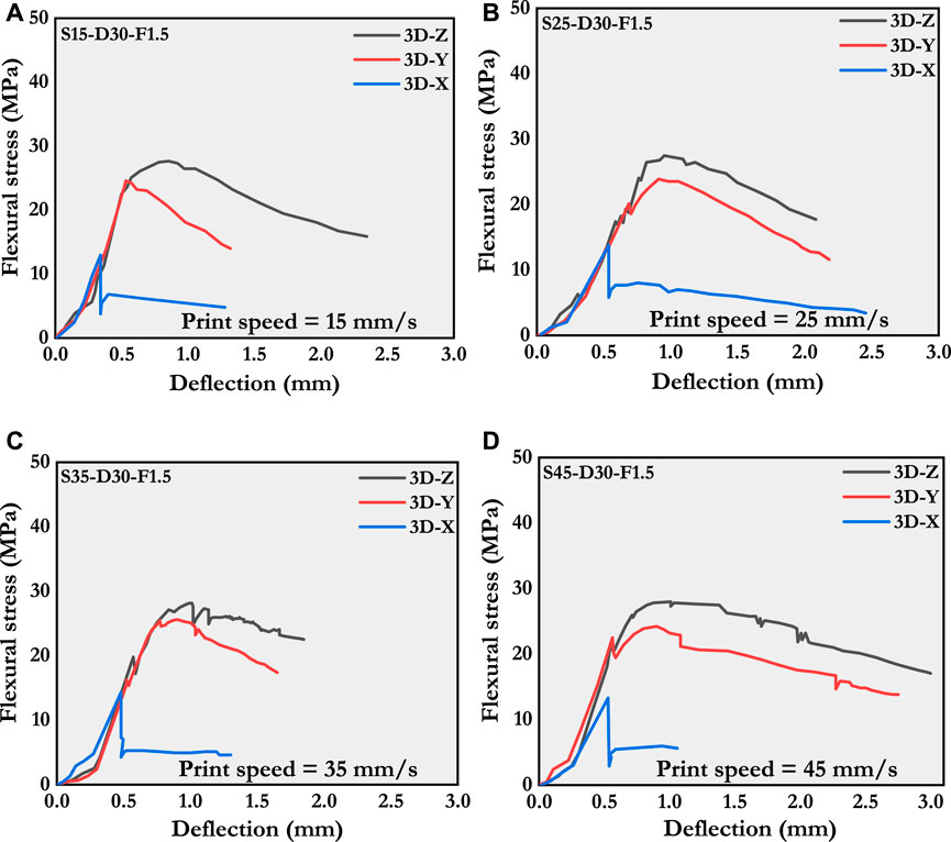
FIGURE 14. Deflection responses under flexural stress of printed specimens at different print speeds. (A) 15 mm/s, (B) 25 mm/s, (C) 35 mm/s, and (D) 45 mm/s.
4.4 Evaluation of fiber alignment
4.4.1 Scheme A: Influence of fiber contents
The study presents the fiber alignment angles of samples containing different fiber contents (1.5% and 3%) achieved through casting and printing methods, and showcases the data in the form of frequency distributions, as shown in Figure 15. The analysis demonstrates that the printed samples display a greater frequency of histograms skewed towards the left side of the graph, suggesting a predominant orientation of the fibers parallel to the direction of print.
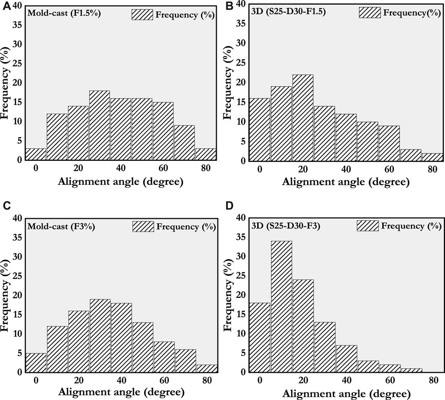
FIGURE 15. Fiber alignment-based frequency distribution of printed and mold-cast specimens with 1.5% and 3% fiber contents. (A) Casted F-1.5%, (B) Printed F-1.5%, (C) Casted F-3%, and (D) Printed F-3%.
However, the specimens prepared through the casting method demonstrate a symmetrical distribution, implying a random arrangement of fibers. This observation aligns with the conclusions drawn from prior research (Kang and Kim, 2012; Amin et al., 2017; Huang et al., 2018) on mold-cast samples. The research results suggest that the printing technique can achieve a more aligned fiber structure compared to the casting method. Figure 16 displays the probability density functions (PDFs) of both printed and mold-cast samples. The probability of fiber alignment between the two angles can be determined by calculating the area under the PDF. This method facilitates the quantitative analysis of fiber alignment in the samples under examination.
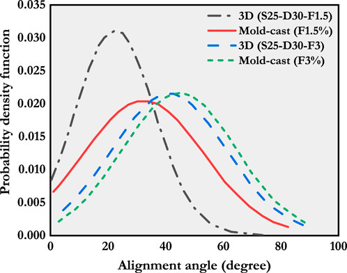
FIGURE 16. Fiber alignment-based PDF curves of printed and mold-cast specimens with 1.5% and 3% fiber contents.
The examination of the PDFs of printed specimens in comparison to the corresponding mold-cast specimens revealed a predominant left-hand positioning of the curves. A notable leftward shift in the PDFs was observed as the fiber content increased from 1.5% to 3%, indicating an intensified physical interaction among the fibers within the designated volume. These findings suggest an enhanced alignment of the fibers in the printing direction, accompanied by an increased occurrence of inter-fiber contacts. In addition, it was observed that the fiber alignment distribution was notably affected by the length of flow, exhibiting a distinct variation as the material path (nozzle extruder) length increased. Consequently, it can be inferred that the alignment of fibers was significantly impacted by the length of flow. The findings of this study reveal that by optimizing the physical characteristics of the fibers and adjusting the printing process parameters, the desired hardened characteristics of the printed specimens can be achieved.
4.4.2 Scheme B: Influence of nozzle diameter
The study examines and presents the analysis of fiber alignment angles in specimens produced by both casting> and printing methods, employing different nozzle diameters. The distribution of these angles is depicted in Figure 17. Furthermore, Figure 18 illustrates the probability density functions (PDFs) of the samples printed using various nozzle diameters. The obtained results reveal a left-skewed pattern in the graph for all printed samples, indicating a predominant fiber arrangement in the parallel plane relative to the direction of the print. These findings imply that the printing direction significantly influences fiber alignment, thereby impacting the hardened performance of the printed samples. In the analysis of the printed samples, a distinct left-skewed pattern was noted in those produced with nozzles having a diameter of less than 20 mm, in comparison to the others.
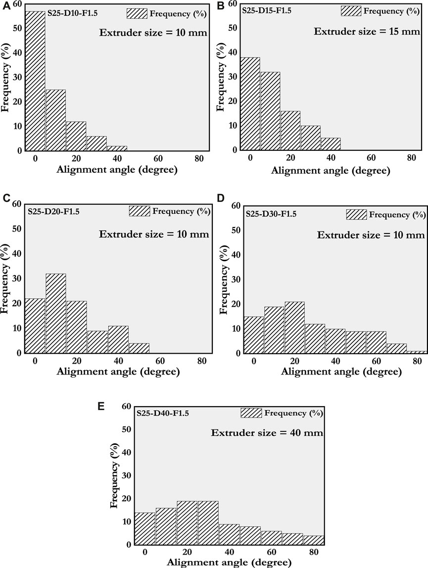
FIGURE 17. Fiber alignment-based frequency distribution of printed samples with various extruder diameters. (A) 10 mm, (B), 15 mm (C), 20 mm (D), 30 mm, and (E) 40 mm.
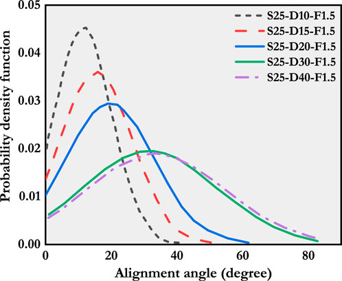
FIGURE 18. Fiber alignment based normalized probability density functions of printed specimens with different diameter nozzles.
It was observed that the samples produced using 10 mm nozzles exhibited the highest frequency of angle alignment below 10°. This observation implies that the influence of nozzle size on fiber alignment becomes less prominent once the ratio of nozzle size to fiber length exceeds a certain threshold. These findings suggest that the size of the nozzle plays a pivotal role in determining the orientation of reinforced fibers in printed samples, but its influence diminishes beyond a specific threshold.
Furthermore, the utilization of larger nozzles, specifically those with diameters of 30 mm and 40 mm in this particular study, resulted in inadequate flow extrusion of the mixture due to reduced convergent flow compared to nozzles with diameters of 10 mm, 15 mm, and 20 mm. Consequently, it can be inferred that the alignment of fibers in the direction of print remains unaffected by the use of nozzles with diameters exceeding the length of fibers present in the mixture. This outcome arises from the fact that the influence of nozzle size on fiber alignment diminishes beyond a certain threshold, indicating that larger nozzle sizes do not significantly impact the arrangement of fibers.
Increasing the nozzle diameter at a constant print speed results in a corresponding increase in the material flow rate. The observation indicated that using larger nozzle diameters, specifically 30 mm and 40 mm, resulted in higher extrusion pressure during the extrusion process in comparison to smaller nozzle sizes. Therefore, ensuring consistency in nozzle size is of paramount importance to maintain a stable extrusion process.
The findings of this study indicate that when using smaller-sized nozzles, there was a greater distribution of fiber alignment in the direction of printing, whereas larger nozzles, specifically those with a diameter greater than 20 mm, had no significant impact on fiber alignment with flow. Therefore, it can be hypothesized that the alignment of fibers is more influenced by smaller diameter nozzles rather than the applied pressure at the extruder during the printing process. This hypothesis is supported by the results obtained from scheme C, which involved varying print speeds.
4.4.3 Scheme C: Influence of print speed
The frequency distribution of fiber alignment angles for specimens produced through mold-casting and printing at different speeds is illustrated in Figure 19. Additionally, the corresponding PDF curves are presented in Figure 20. The PDF analysis indicates that the specimen printed at a speed of 45 mm/s displayed a left-skewed behavior, with little impact from the other print speeds on fiber alignment. Nevertheless, when compared to the mold-cast specimens in scheme A, all printing speeds showcased improved fiber alignment. This observation further reinforces the assertion made in scheme B, which suggests that the fiber arrangement in printable concrete is minimally affected by the mechanical pressure exerted by the extruder, owing to its high viscosity and yield stress. The fundamental properties of printable concrete, namely, its high viscosity and yield stress, play a crucial role in ensuring the structural integrity of the printed object and its ability to withstand the load it will bear (Roussel, 2018). Consequently, it becomes apparent that narrow diameter nozzles exert a more significant influence on the alignment of fibers in the direction of print when compared to their wider diameter counterparts, specifically those with diameters of 30 mm and 40 mm.
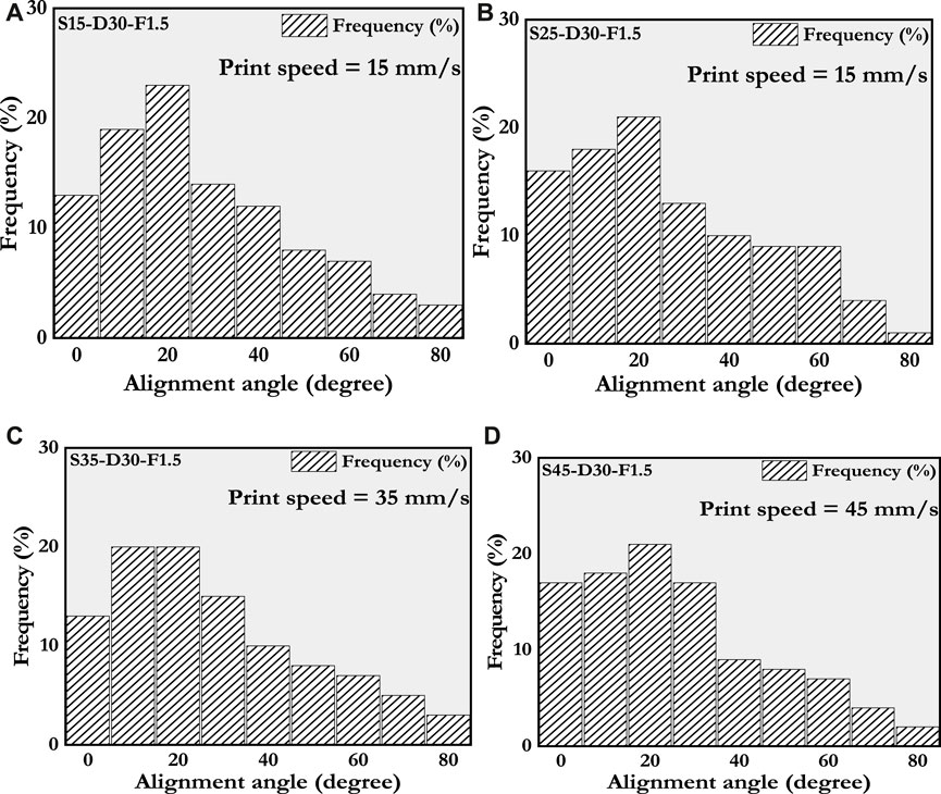
FIGURE 19. Fiber alignment-based frequency distribution of printed specimens at different print speeds. (A) 15 mm/s, (B) 25 mm/s, (C) 35 mm/s, and (D) 45 mm/s.
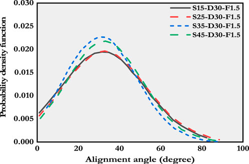
FIGURE 20. Fiber alignment based normalized probability density functions of printed samples at various print speeds.
In this study, it was observed that the orientation of fibers along the direction of the print increases with the application of extrusion pressure during the printing process compared to casting (as demonstrated in scheme A). However, the influence of pressure on fiber alignment in printed specimens was found to be minimal, suggesting that further increases in pressure may not significantly impact the horizontal fiber arrangement with respect to the direction of the print. Therefore, it can be inferred that the relationship between extrusion pressure and fiber alignment in printed specimens is non-linear. Moreover, based on the findings, it can be concluded that the printing process is a suitable method for controlling the fiber arrangement in the printed concrete.
4.5 Summary
The compressive strength of the mold-cast specimens was observed to be higher than the Y and Z directions of the printed specimens, while slightly lower than the X-direction of the printed specimens. The compressive strength of both the printed and mold-cast specimens ranged from 120 to 155 MPa in all directions, with different fiber contents ranging from 0% to 3%. The printed specimen with 3% fiber content and a 10 mm nozzle diameter displayed the highest fracture strength. However, the different print speeds used during the printing process did not significantly affect the fiber alignment or the fracture strength of the printed specimens.
The results of the study show that using the 3D-X printing technique with a 1.5% fiber content led to specimens exhibiting higher residual strengths after reaching their maximum load compared to those with a 3% fiber content. In relation to the impact of diameter, it can be deduced that when the nozzle diameter of the printed sample surpasses 20 mm, the effect of nozzle size on fiber alignment decreases. It is crucial to emphasize that these conclusions hold significance in averting brittle or DS behavior in 3D printing and can contribute to achieving the best possible fiber alignment. Furthermore, the data suggests that print speed has a negligible impact on the stress-deflection response of the printed specimens.
5 Conclusion
The present research paper undertook an investigation into the effects of various nozzle diameters, print speeds, and fiber contents on fiber alignment and their subsequent ramifications on the hardened properties of additively manufactured ultra-high-performance fiber-reinforced composites (UHPC). Additionally, a comparison was made between the obtained results and those of mold-cast specimens. The conclusions derived from the findings are outlined as follows:
1) The process of three-dimensional (3D) printing exerts a substantial influence on the alignment of fibers within ultra-high-performance fiber-reinforced composites. Notably, samples printed with fiber contents of 1.5% and 3% exhibited a greater degree of fiber orientation in the direction of printing when compared to those prepared via the casting method. Furthermore, specimens with higher fiber content demonstrated a more pronounced level of alignment in the direction of printing.
2) The diameter of the nozzle utilized plays a pivotal role in achieving optimal fiber alignment in the realm of 3D printing. Specifically, it was discovered that nozzles with smaller diameters proved to be more effective in attaining desirable fiber alignment in the direction of printing. This observation is further supported by the fact that specimens printed using a 10 mm diameter nozzle displayed approximately 30% higher fracture strength in comparison to those printed using a 40 mm diameter nozzle.
3) The distribution of fiber alignment within printed specimens remained consistent across all tested print speeds, and no direct correlation was established between print speeds and extrusion pressure in relation to an increase in fiber alignment.
4) By optimizing the orientation of fibers in the direction of printing, the flexural properties of printed materials can be positively influenced. Notably, the fracture strength of the printed samples experienced an approximate 40% increase for a fiber content of 3%. Furthermore, specimens printed at different speeds exhibited similar behavior in terms of flexural strength.
Data availability statement
The original contributions presented in the study are included in the article/Supplementary material, further inquiries can be directed to the corresponding authors.
Author contributions
QS: Conceptualization, Data curation, Formal Analysis, Investigation, Methodology, Writing–original draft. NA: Writing–review and editing. MA: Formal Analysis, Writing–original draft. ES: Funding acquisition, Writing–review and editing. BT: Supervision, Writing–review and editing.
Funding
The author(s) declare financial support was received for the research, authorship, and/or publication of this article. This work was supported by Deputyship for Research and innovation, Ministry of education in Saudi Arabia for funding this research work through the project number ISP23-120.
Conflict of interest
The authors declare that the research was conducted in the absence of any commercial or financial relationships that could be construed as a potential conflict of interest.
Publisher’s note
All claims expressed in this article are solely those of the authors and do not necessarily represent those of their affiliated organizations, or those of the publisher, the editors and the reviewers. Any product that may be evaluated in this article, or claim that may be made by its manufacturer, is not guaranteed or endorsed by the publisher.
References
Alam, S., Gebremedhin, A. W., Atomsa, H. W., and Khan, A. H. (2022). A comparative study between strength and durability of bentonite and natural gum stabilised sand. Geomechanics Geoengin. 17 (6), 1722–1734. doi:10.1080/17486025.2021.1961026
Alfani, R., and Guerrini, G. J. M. (2005). Rheological test methods for the characterization of extrudable cement-based materials—a review. Structures 38, 239–247. doi:10.1617/14191
Amin, A., Pimentel, M., and Nunes, S. (2017). Influence of fibre orientation on the tensile behaviour of ultra-high performance fibre reinforced cementitious composites. Cem. Concr. Res. 97, 28–40. doi:10.1016/j.cemconres.2017.03.007
Asprone, D., Menna, C., Bos, F. P., Salet, T. A. M., Mata-Falcon, J., and Kaufmann, W. (2018). Rethinking reinforcement for digital fabrication with concrete. Cem. Concr. Res. 112, 111–121. doi:10.1016/j.cemconres.2018.05.020
Association Francaise de G’ enie Civil (AFGC) (2002). Ultra high-performance fiber reinforced concretes: interim recommendations. AFGC Scientific and Technical Documents.
ASTM (2018). C33/C33m-18, standard specification for concrete aggregates. West Conshohocken, PA: ASTM International. doi:10.1520/C0033_C0033M-18
ASTM (2020). C150/C150m-20, standard specification for sulfoaluminate and portland cement. West Conshohocken, PA: ASTM International. doi:10.1520/C0150_C0150M-20
Bosco, B., and Salet, T. A. M. (2019). Ductility of 3D printed concrete reinforced with short straight steel fibers. Virt. Phy. Prototyp. 14 (2), 160–174. doi:10.1080/17452759.2018.1548069
Buswell, R. A., Soar, R., and Gibb, A. G. (2007a). Freeform construction: mega-scale rapid manufacturing for construction. Autom. Constr. 16 (2), 224–231. doi:10.1016/j.autcon.2006.05.002
Buswell, R. A., Soar, R. C., Gibb, A. G., and Thorpe, A. (2007b). Freeform construction: mega-scale rapid manufacturing for construction. Autom. Constr. 16 (2), 224–231. doi:10.1016/j.autcon.200605.002
Figueiredo, S. C., Rodríguez, C. R., Ahmed, Z. Y., Bos, D. H., Xu, Y., Salet, T. M., et al. (2020). Mechanical behavior of printed strain hardening cementitious composites. Mater 13 (10), 2253. doi:10.3390/ma13102253
Hamidi, F., and Aslani, F. (2019). Additive manufacturing of cementitious composites: materials, methods, potentials, and challenges. Build. Mater. 218, 582–609. doi:10.1016/j.conbuildmat.2019.05.140
Huang, H., Gao, X., Li, L., and Wang, H. (2018). Improvement effect of steel fiber orientation control on mechanical performance of UHPC. Constr. Build. Mater. 188, 709–721. doi:10.1016/j.conbuildmat.2018.08.146
Jagadesh, P., Ramachandramurthy, A., Rajasulochana, P., Hasan, M. A., Murugesan, R., Khan, A. H., et al. (2023). Effect of processed sugarcane bagasse ash on compressive strength of blended mortar and assessments using statistical modelling. Case Stud. Constr. Mater. 19, e02435. doi:10.1016/j.cscm.2023.e02435
Kang, S.-T., and Kim, J.-K. (2012). Investigation on the flexural behavior of UHPCC considering the effect of fiber orientation distribution. Constr. Build. Mater. 28 (1), 57–65. doi:10.1016/j.conbuildmat.2011.07.003
Khoshnevis, B. (2004). Automated construction by contour crafting—related robotics and information technologies. Autom. Constr. 13 (1), 5–19. doi:10.1016/j.autcon.2003.08.012
Kruger, J., Cho, S., Zeranka, S., Viljoen, C., and van Zijl, G. (2020). 3D concrete printer parameter optimisation for high rate digital construction avoiding plastic collapse. Comp. Part B 183, 107660. doi:10.1016/j.compositesb.2019.107660
Le, T. T., Austin, S. A., Lim, S., Buswell, R. A., Gibb, A. G., and Thorpe, T. (2012). Mix design and fresh properties for high-performance printing concrete. Mater. Struct. 45, 1221–1232. doi:10.1617/s11527-012-9828-z
Lim, S., Buswell, R. A., Le, T. T., Austin, S. A., Gibb, A. G., and Thorpe, T. (2012). Developments in construction-scale additive manufacturing processes. Constr 21, 262–268. doi:10.1016/j.autcon.2011.06.010
Liu, X., and Sun, B. (2021). The influence of interface on the structural stability in 3D concrete printing processes. Addit. Manuf. 48, 102456. doi:10.1016/j.addma.2021.102456
Ma, G., Li, Z., and Wang, L. (2018). Printable properties of cementitious material containing copper tailings for extrusion based 3D printing. Constr. Build. Mater. 162, 613–627. doi:10.1016/j.conbuildmat.2017.12.051
Ma, G., Li, Z., Wang, L., Wang, F., and Sanjayan, J. (2019). Mechanical anisotropy of aligned fiber reinforced composite for extrusion-based 3D printing. Constr. Build. Mater. 202, 770–783. doi:10.1016/j.conbuildmat.2019.01.008
Martinez, S., Jardon, A., Gimenez, A., Balaguer, C., Navarro, J., and Barcena, C. (2008). “Robotized lean assembly in the building industry,” in Proceedings of the 25th International Symposium on Automation and Robotics in Construction (ISARC), Vilnius, Lithuania, June 26-29, 2008, 195–201.
Meshram, S., Raut, S. P., Ansari, K., Madurwar, M., Daniyal c, Md, Khan, M. A., et al. (2023). Waste slags as sustainable construction materials: a compressive review on physico mechanical properties. J. Mater. Res. Technol. 23, 5821–5845. March–April. doi:10.1016/j.jmrt.2023.02.176
Miao, E., Wu, L., and Sun, L. X. (2020). Enzyme-catalysed mineralisation experiment study to solidify desert sands. Sci. Rep. 10, 10611. doi:10.1038/s41598-020-67566-6
Nerella, V. N., and Mechtcherine, V. (2019). Studying the printability of fresh concrete for formwork-free concrete onsite 3D printing technology (CONPrint3D), 3DCP Tech. Elsevier, 333–347.
Neupane, R. P., Imjai, T., Makul, N., Garcia, R., Kim, B., and Chaudhary, S. (2023). Use of recycled aggregate concrete in structural members: a review focused on Southeast Asia. J. Asian Arch. Build. Engg, 1–24. doi:10.1080/13467581.2023.2270029
Ogura, H., Nerella, V., and Mechtcherine, V. (2018). Developing and testing of strain-hardening cement-based composites (SHCC) in the context of 3D-printing. Mater 11 (8), 1375. doi:10.3390/ma11081375
Panda, B., Lim, J. H., and Tan, M. J. (2019). Mechanical properties and deformation behaviour of early age concrete in the context of digital construction. Comp. Part B 165, 563–571. doi:10.1016/j.compositesb.2019.02.040
Paruthi, S., Husain, A., Alam, P., Khan, A. H., Hasan, M. A., and Hassan, M. M. (2022). A review on material mix proportion and strength influence parameters of geopolymer concrete: application of ANN model for GPC strength prediction. Constr. Build. Mater. 356, 129253. 21 November. doi:10.1016/j.conbuildmat.2022.129253
Paruthi, S., Khan, A. H., Kumar, A., Kumar, F., Hasan, M. A., Magbool, H. M., et al. (2023a). Sustainable cement replacement using waste eggshells: a review on mechanical properties of eggshell concrete and strength prediction using artificial neural network. Case Stud. Constr. Mater. 18, e02160. doi:10.1016/j.cscm.2023.e02160
Paruthi, S., Rahman, I., Husain, A., Hasan, M. A., and Khan, A. H. (2023b). Effects of chemicals exposure on the durability of geopolymer concrete incorporated with silica fumes and nano-sized silica at varying curing temperatures. Materials 16, 6332. doi:10.3390/ma16186332
Paruthi, S., Rahman, I., Husain, A., Khan, A. H., Manea Saghin, A.-M., and Sabi, E. (2023c). A comprehensive review of nano materials in geopolymer concrete: impact on properties and performance. Dev. Built Environ. 16, 100287. doi:10.1016/j.dibe.2023.100287
Pérez, V. V., and Medina, N. F. (2018). Alignment of hooked-end fibres in matrices with similar rheological behaviour to cementitious composites through homogeneous magnetic fields. Constr. Build. Mater. 163, 256–266. doi:10.1016/j.conbuildmat.2017.12.084
Qamar, S., and Li, F. Y. (2023). An innovative method for buildability assessment of 3d printed concrete at early-ages. Constr. Build. Mater. 403 (2023), 133167. doi:10.1016/j.conbuildmat.2023.133167
Rahul, A. V., Santhanam, M., Meena, H., and Ghani, Z. (2019). 3D printable concrete: mixture design and test methods. Compos 97, 13–23. doi:10.1016/j.cemconcomp.2018.12.014
Roussel, N. (2006). A thixotropy model for fresh fluid concretes: theory, validation and applications. Cem. Concr. Res. 36 (10), 1797–1806. doi:10.1016/j.cemconres.2006.05.025
Roussel, N. (2018). Rheological requirements for printable concretes. Cem. Concr. Res. 112, 76–85. doi:10.1016/j.cemconres.2018.04.005
Saba, A. M., Khan, A. H., Akhtar, M. N., Khan, N. A., Saeid Rahimian Koloor, S., Petru, M., et al. (2021). Strength and flexural behavior of steel fiber and silica fume incorporated self-compacting concrete. J. Mater. Res. Technol. 12, 1380–1390. doi:10.1016/j.jmrt.2021.03.066
Shahzad, Q., Shen, J., Naseem, R., Yao, Y., Waqar, S., and Liu, W. (2021a). Influence of phase change material on concrete behavior for construction 3D printing. Constr. Build. Mater. 309, 125121. doi:10.1016/j.conbuildmat.2021.125121
Shahzad, Q., Shen, J., Naseem, R., Yao, Y., Waqar, S., Liu, W. J. C., et al. (2021b). Influence of phase change material on concrete behavior for construction 3D printing. Constr. Build. Mater. 309, 125121. doi:10.1016/j.conbuildmat.2021.125121
Shahzad, Q., Umair, M., and Waqar, S. (2023). Bibliographic analysis on 3D printing in the building and construction industry: printing systems, material properties, challenges, and future trends. JSCMT 7 (3), 198–220. doi:10.47481/jscmt.1182627
Shahzad, Q., Wang, X., Wang, W., Wan, Y., Li, G., Ren, C., et al. (2020a). Coordinated adjustment and optimization of setting time, flowability, and mechanical strength for construction 3D printing material derived from solid waste. Constr. Build. Mater. 259, 119854. doi:10.1016/j.conbuildmat.2020.119854
Shahzad, Q., Wang, X., Wang, W., Wan, Y., Li, G., Ren, C., et al. (2020b). Coordinated adjustment and optimization of setting time, flowability, and mechanical strength for construction 3D printing material derived from solid waste. 3D Print. material Deriv. solid waste 259, 119854. doi:10.1016/j.conbuildmat.2020.119854
Suiker, A. (2018). Mechanical performance of wall structures in 3D printing processes: theory, design tools and experiments. Inter. J. Mech. Sci. 137, 145–170. doi:10.1016/j.ijmecsci.2018.01.010
Vermeer, P. A., and Borst, De (1984). Non-associated plasticity for soils, concrete and rock. Netherlands:HERON.
Warszawski, A., and Navon, R. (1998). Implementation of robotics in building: current status and future prospects. J. Constr. Eng. Manag. 124 (1), 31–41. doi:10.1061/(asce)0733-9364(1998)124:1(31)
Wijffels, M. J., Wolfs, M., Suiker, A. S. J., and Salet, T. A. M. (2017). Magnetic orientation of steel fibres in self-compacting concrete beams: effect on failure behaviour. Cem. Concr. Comp. 80, 342–355. doi:10.1016/j.cemconcomp.2017.04.005
Wille, K., Naaman, A. E., and Parra-Montesinos, G. J. (2011). Ultra-high-performance concrete with compressive strength exceeding 150 MPa (22 ksi): a simpler way. ACI Mater. J. 108 (1). doi:10.14359/51664215
Yekai, Y., Wu, C., Liu, Z., and Zhang, H. (2022). 3D-printing ultra-high performance fiber-reinforced concrete under triaxial confining loads. Addit. Manuf. 50, 102568. doi:10.1016/j.addma.2021.102568
Keywords: 3D printing, ultra-high-performance concrete, fiber alignment, print speed, nozzle diameter, mechanical properties
Citation: Shahzad Q, Abbas N, Akbar M, Sabi E, Thomas BS and Arshid MU (2024) Influence of print speed and nozzle diameter on the fiber alignment in 3D printed ultra-high-performance concrete. Front. Mater. 11:1355647. doi: 10.3389/fmats.2024.1355647
Received: 14 December 2023; Accepted: 19 February 2024;
Published: 12 March 2024.
Edited by:
Pervez Alam, Baba Ghulam Shah Badshah University, IndiaReviewed by:
Seun Owoeye, Federal Polytechnic Ado Ekiti, NigeriaThanongsak Imjai, Walailak University, Thailand
Ali Firoozi, University of Botswana, Botswana
Shahzada Junaid, Budapest University of Technology and Economics Budapest, Hungary in collaboration with reviewer AF
Copyright © 2024 Shahzad, Abbas, Akbar, Sabi, Thomas and Arshid. This is an open-access article distributed under the terms of the Creative Commons Attribution License (CC BY). The use, distribution or reproduction in other forums is permitted, provided the original author(s) and the copyright owner(s) are credited and that the original publication in this journal is cited, in accordance with accepted academic practice. No use, distribution or reproduction is permitted which does not comply with these terms.
*Correspondence: Muhammad Akbar, YWtiYXJtb2hhbW1hZDAwOTJAZ21haWwuY29t; Ehab Sabi, ZXNhYmlAamF6YW51LmVkdS5zYQ==
 Qamar Shahzad
 Nadeem Abbas2
 Muhammad Akbar
 Ehab Sabi
 Blessen Skariah Thomas
