 Muhammad Alamgeer Shams1
 Naraindas Bheel1*
 Mohsin Ali2
 Mahmood Ahmad3,4
 Taoufik Najeh5*
 Yaser Gamil6Hamad R. Almujibah7Omrane Benjeddou8
- 1Department of Civil and Environmental Engineering, Universiti Teknologi PETRONAS, Bandar SeriIskandar, Malaysia
- 2Graduate School of Urban Innovation, Department of Civil Engineering, Yokohama National University, Yokohama, Japan
- 3Institute of Energy Infrastructure, Universiti Tenaga Nasional, Kajang, Malaysia
- 4Department of Civil Engineering, University of Engineering and Technology Peshawar (Bannu Campus), Bannu, Pakistan
- 5Department of Civil, Environmental and Natural Resources Engineering, Luleå University of Technology, Luleå, Sweden
- 6Department of Civil Engineering, School of Engineering, Monash University Malaysia, Subang Jaya, Malaysia
- 7Department of Civil Engineering, College of Engineering, Taif University, Taif, Saudi Arabia
- 8Department of Civil Engineering, College of Engineering, Prince Sattam Bin Abdulaziz University, Alkharj, Saudi Arabia
Concrete has a great capacity to withstand compressive strength, but it is rather weak at resisting tensile stresses, which ultimately result in the formation of cracks in concrete buildings. The development of cracks has a significant impact on the durability of concrete because they serve as direct pathways for corrosive substances that harm the concrete’s constituents. Consequently, the reinforced concrete may experience degradation, cracking, weakening, or progressive disintegration. To mitigate such problems, it is advisable to include discrete fibres uniformly throughout the concrete mixture. The fibers function by spanning the voids created by fractures, therefore decelerating the mechanism of fracture initiation and advancement. It is not practical to assess the beginning and spread of cracks when there are uncertainties in the components and geometrical factors through probabilistic methods. This research examines the behaviour of variation of steel fibers in Fiber Reinforced Concrete (FRC) via Finite Element Method (FEM) modeling. In this study also the fracture parameters such as fracture energy, and fracture toughness have been computed through FEM analysis. The FEM constitutive model developed was also validated with the experimental result. The compressive strength of the developed constitutive model was 28.50 MPa which is very close to the 28-day compressive strength obtained through the experiment, i.e., 28.79 MPa. Load carrying capacity obtained through FEM was 7.9 kN, 18 kN, and 24 kN for three FEM models developed for three varying percentages of steel fiber 0.25%, 0.5%, and 0.75% respectively. The study developed a FEM model which can be used for calculating the fracture parameters of Steel Fibre-Reinforced Concrete (SFRC).
1 Introduction
Cracks in concrete are a constant and unavoidable occurrence. They may manifest due to many factors, including contraction, thermal dilation, and excessive stress (Kiran et al., 2017a). The issue of what precisely triggers the formation and spread of numerous fissures in what seems to be an arbitrary arrangement remains unanswered, at least in a systematic manner. The presence of randomized fractures in concrete structures may be attributed to the intrinsic diversity of the components applied (Alava et al., 2006; Seagraves and Radovitzky, 2010; Kiran et al., 2017a; Ai et al., 2023). The constituents of concrete may exhibit variations in their quantities and chemical substances, resulting in notable disparities in the characteristics of distinct concrete mixes (Jiao et al., 2017; Tarabin et al., 2023a). Another determinant is how concrete undergoes the curing process of curing. The ultimate characteristics of the construction would not be completely apparent once a certain time had elapsed after its placement, resulting in concentrated pressure inside the concrete that might cause the development and spread of fractures (Cement Association, 2001; Tarabin et al., 2023a). Environmental factors may also contribute to the development of spontaneous fissures. Concrete may develop fractures due to temperature variations and variations in moisture, which cause it to extend and shrink. Although fractures in concrete may seem random, they typically exhibit discernible trends (Zhang et al., 2000; Safiuddin et al., 2018). Fractures often align with paths of less resistance and are frequently spread in a meandering configuration. The presence of cracks in a concrete beam does not always indicate structural failure (Tarabin et al., 2023a). Nevertheless, if the fractures exhibit significant size or are expanding, the structural beam may pose a safety hazard and need repair or replacement.
Forecasting the spread of cracks is a complex undertaking. The characteristics of the materials, the geometry of the construction, the pressure conditions, the surrounding environment, and the uncertainties associated with all of these factors generally influence the speed at which cracks propagate (Yazici et al., 2007; Merta and Tschegg, 2013; Wang et al., 2022; Zhang et al., 2023). Several empirical formulas have been suggested to predict the pace at which fractures spread in concrete. The Paris law is a frequently utilized mathematical expression. As per the Paris rule, the frequency at which cracks spread is directly related to the multiplication of the stress intensity coefficient and the dimension of the fracture. Additional factors that may impact the speed at which a crack spreads comprise deterioration, substance defects, and the existence of foreign particles inside the substance. The occurrence and spread of cracks in FRC exhibit distinct differences compared to traditional concrete. In FRC, the majority of the load is transmitted by the fractures in samples, whereas in FRC, the primary load transmission occurs via the reinforcement made from steel. The steel reinforcing in normal reinforced concrete beams primarily contributes to the beam’s tensile strength (Tiberti et al., 2015; Amin and Gilbert, 2019; Conforti et al., 2019). Whenever a force is exerted on the structure, the steel reinforcing counteracts the stress by undergoing elongation, while the concrete mostly contributes to the compressive strength. The beam’s ability to resist breaking during typical stress circumstances is attributed to its high tensile and compressive strengths. However, the steel reinforcing does not contribute significantly to the tensile strength of a FRC structure. Concrete and fibers exhibit tensile strength by breaking in response to applied stresses (Tarabin et al., 2023a). The primary purpose of the steel reinforcing in FRC frameworks is to prevent excessive propagation of the concrete underneath stress, hence preventing beam failure. In general, FRC frameworks provide several benefits compared to conventionally reinforced concrete frames. They exhibit greater strength, increased ductility, and reduced vulnerability to failure when subjected to severe loads. Moreover, their accessibility and longevity have led to a growing popularity of these materials in residential buildings (Zollo, 1997; Thomas and Ramaswamy, 2007). Rong et al., 2021 performed controlled shrinkage ring experiments on FRC samples with several different steel fiber volume percentages. They also devised a computational approach relying on fracture mechanics to analyze the fracturing behavior.
The researchers discovered that the fiber volume percentage had a substantial impact on the fracture characteristics of the FRC ring when subjected to controlled shrinkage (Combrinck, 2012; Maritz, 2012). Additionally, it was discovered that the suggested method for crack start and spread could proficiently analyze the entire crack mechanism of the FRC when subjected to restricted shrinkage. The experts’ results have multiple ramifications for the use of FRC in the building industry. Initially, it is recommended to meticulously evaluate the fiber volume percentage while using FRC in situations where maintaining resistance against fracturing is crucial (Hollaway and Leeming, 1999; Tarabin et al., 2023a). Furthermore, the suggested method for crack formation and spreading can evaluate the likelihood of cracking in FRC when subjected to constrained shrinkage. Taheri et al., 2020 created a predictive approach for estimating the overall fracture size and spacing of flexural components composed of FRC, which incorporates longitudinal steel rods. The behavior of FRC is simulated using a link between load and fracture size. The relationship between the concrete and longitudinal rebar is modeled using a FEM model that shows the correlation involving sliding and shear stress, based on scientific findings. The simulation was evaluated by replicating laboratory evaluations performed on FRC beams with varying geometries, FRC material characteristics, and flexural reinforcing arrangements. The algorithm accurately estimated the overall fracture size and overall fracture gap at the point when the fracturing had stabilized.
In their study, Ding et al., 2021 investigated a different approach to accurately detecting the position of cracks in concrete when subjected to bending. A total of six electrodes were used between two inner electrodes to measure the voltage, which indicated both the location and spreading of cracks. The load-time and voltage-time curves can be categorized into three phases: two inflection points that represent the states of being uncracked, breaking, and fracture development.
An exponential expression may describe the correlation between voltage and crack opening displacement (COD). The investigators demonstrated the approach’s excellent efficacy by establishing a simultaneous occurrence of voltage variation and fracture. The technology suggested in current research has the potential to detect the emergence and expansion of cracks in concrete buildings by raising the number of electrodes. The scientists discovered a simultaneous occurrence of voltage change and crack formation. They also found that the approach suggested in this research might be used to detect the development and expansion of cracks in concrete components. The primary aim of this work is to examine the fracturing behavior and trends of FRC beams from a probability perspective. Another aim is to deliver a comprehensive deterministic approach that may be utilized by developers and assessment professionals. Implementing such a model would enable more precise forecasts of the residual time required for necessary operations and the average duration before a breakdown occurs. This work includes an experimental program in which FRC beams were fabricated using varying fiber doses. The cast was subjected to loading until they reached their maximum capacity, failing. The resulting fracture formations were recorded and utilized to construct a database of pictures, which were then employed in the probabilistic assessment.
2 Research methods
2.1 Experimental data
International standards employ a variety of tests to evaluate the mechanical properties of FRC composites. The material is typically described using small beams that are subjected to flexural stress. To establish important parameters, following JCI-SF4 and ASTM C1609/C1609M a bending test on unnotched prismatic specimens, and following EN14651-20 a three-point bending test on notched specimens, was performed. Following ASTM C1609 and EN14651-2005, FRC beams were cast both with and without notches by Tarabin et al., 2023a. The cast beam was 600 mm in length, with 450 mm in clear span L, and L/3 as the width and depth of the beam which is 150 mm. The notch’s dimensions—5 mm for the opening and 25 mm for the depth—also met EN14651-2005 requirements. A three-point bending test on the casting beam was applied at the center of the beam span with two roller supports at a distance of 25 mm from the center of the support to the nearest edge of the beam. Concrete examples of FRC were created using a mix with varying steel fibers of 0.25%, 0.5%, and 0.75% percentages by volume. The study employed hook-end steel fibers with dimensions of,
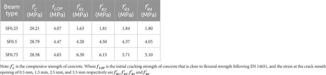
TABLE 1. Mechanical properties of fiber-reinforced mix (Tarabin et al., 2023a).
2.2 Numerical modelling
A numerical model of the tested notch beams was developed in DIANA fea (“DIANA Finite Element Analysis Release Notes Release 10.4.” A two-dimensional-length FEM model of the tested FRC beams with different steel fiber ratios was developed. FRC beam along with loading steel plates and supports were modelled with a regular plane stress element type. To model the beam and plates, we used 2D plane stress 8-noded quadrilateral iso-parametric elements called Q8MEM. These elements have 18 degrees of freedom. Additionally, interface line elements L8IF were used between the FRC beams and the steel plates. To perform the NLFEA, the load was applied in the form of displacement at a rate of 1 mm. A Newton-Raphson iteration method was employed with a convergence tolerance of 0.001 to perform the analysis. As in 3-point bending test, a notch beam is supported by two roller supports and load at the top similar boundary conditions were given to the FEM model with roller support at one end and pin support at the other end.
A coarse mesh of size 15 mm was selected for the complete model however a fine mesh of size 4 mm was selected near the notch of the beam to get more accuracy in the result. A linear relationship between the Figures 1A, B below shows the geometry and mesh of the FRC beam model.
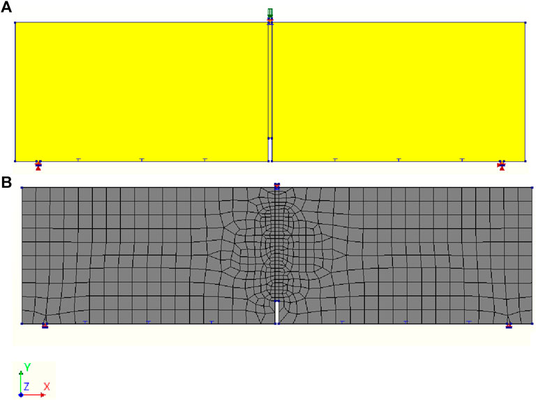
FIGURE 1. Non-linear analysis model (A) Geometry of the FEM model, and (B) Mesh of the FEM model with fine mesh at the notch area.
The DIANA material model often employs a smeared crack technique. For the cracking behavior of reinforced concrete and SFRC, DIANA offers a total strain crack model. For SFRC modeling, an official tensile curve called FRCCON has been provided for a few years. An input stress-CMOD or stress-strain relation may describe the concrete’s softening behavior when mixed with steel fibers. The Model Code 2010 and/or experiments on small bending prisms may be used to determine the parameters of this tensile curve. These experimentally-derived parameters are detailed in Table 1 for this research. The constitutive model of the FRC beam is discussed below in detail.
2.3 Constitutive model for fiber reinforced concrete
A smeared crack approach is used FEM modeling for the cracking behaviour in concrete. In the smeared cracking approach, a rotating crack model is adopted for the cracking propagation along the FRC. In the rotating crack model, the crack direction keeps on rotating under the load throughout the material. In the rotating crack approach as the tensile stress increases the ultimate tensile strength of concrete, a crack initiates and propagates in that direction.
For FRC’s compressive behaviour, a parabolic model as shown below is considered in this study. The parabolic model is based on the fracture energy of concrete as the er following expressions provided in Eqs 1–4, and Figure 2.
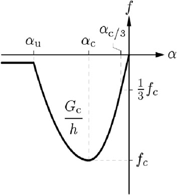
FIGURE 2. Constitutive models for compression non-linear behaviour of FRC.
Where
The above compression curve in DIANA can be explained as
Where
The residual flexural tensile strength of an SFRC material is used to characterize its tensile behaviour. This strength is obtained from either the load against the crack mouth opening displacement curve or the load versus deflection curve that is obtained from the bending test. The formulae to calculate residual flexural strength by using Eq. 5,
Where
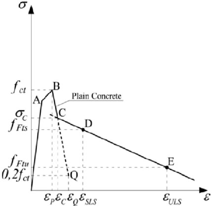
FIGURE 3. Stress-Strain curve for FRC based on fib 2010 (Di Prisco et l., 2013).
The corresponding values of the tensile stress-strain constitutive model with different steel fiber ratios were obtained from the experimental results as Tabled in Table 1. The difference of the residual flexural strength during the experiment was incorporated in DIANA fea to simulate the behavior of steel fibers in concrete. The linear mechanical properties of FRC for the non-linear FEM model are summarized in Table 2.
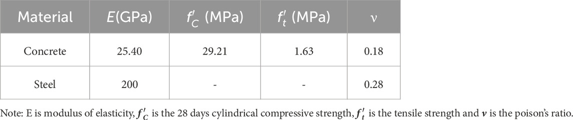
TABLE 2. Material properties for non-linear FEM of FRC beams (Tarabin et al., 2023a).
2.4 Constitutive model for steel
The supports and the loading steel plate were considered as linear material during the testing. The linear material properties are given below in Table 3.
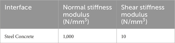
TABLE 3. Steel concrete interface characteristics for non-linear FEM.
2.5 Validation of developed constitutive model
For the validation of the above constitutive model, a compressive cylinder test model was developed in DIANA fea to validate the experimental results with the developed FEM model. For, this purpose a cylinder with material properties of the SF0.5 model was developed as shown in Figure 4. SF0.5 was modeled because in the experiment a little change in compressive strength and modulus of elasticity had been reported by Tarabin et al., 2023a among three samples of FCR. The load was applied in displacement form at a rate of 1 mm. Also, the mesh size was kept 15 mm similar to the mesh size in the original beam model. The load-displacement curve for the compressive strength cylinder of SF0.5 is shown in Figure 4B. The calculated compressive strength comes out to be 28.50 MPa which is almost equal to the experimental result of 28.79 MPa.
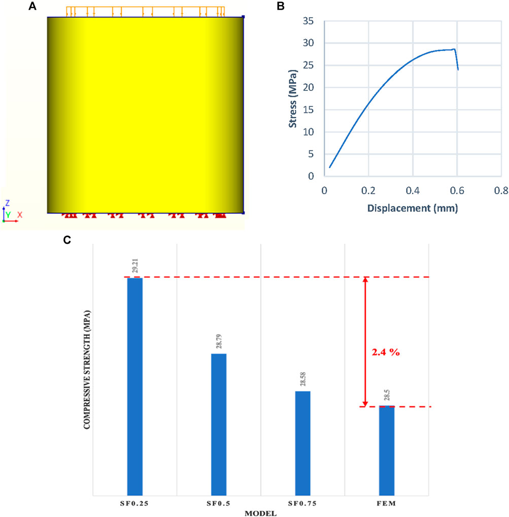
FIGURE 4. (A) Geometry of FEM model of compressive strength cylinder with load at the top face and fixed end support at the bottom face, (B) Compressive stress vs. displacement curve of the FEM model of cylinder, and (C) Compressive strength comparison of FEM model with the experimental results.
A mesh analysis was conducted with three different mesh sizes, i.e., 2 mm, 4 mm, and 10 mm, element size. The same mesh sizes were considered around the notch area and the mesh analysis result is shown in Figure 5. These mesh sizes were selected for the edges of the tip of the notch as that is the most sensitive area due to crack propagation and load applied. It can be seen that the selected mesh size (4 mm) has reached a displacement of 4.2 mm which is more than the CMOD value of 3.5 mm which is necessary to obtain the fracture energy of SFRC. However, in the coarse and fine mesh, the divergence in analysis occurred much earlier than the load CMOD value at 3.5 mm.
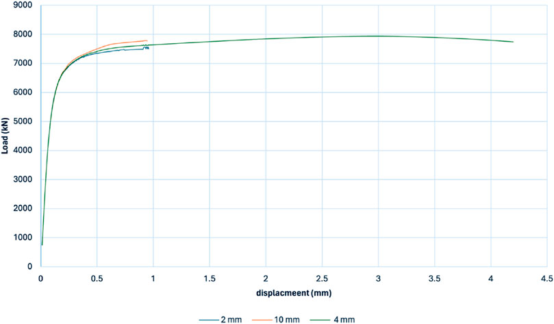
FIGURE 5. Mesh sensitivity analysis with fine, medium, and coarse mesh sizes in SFRC FEM model.
2.6 Calculated parameters for Finite element method model
The NLFEA was conducted to evaluate the effect of steel fibers on the fracture parameters of FRC. The parameters calculated are Fracture energy and Fracture toughness. The fracture parameters are calculated by the Eqs 6–8.
1- Fracture Energy Calculation.
Fracture energy is calculated by a method described by the Japanese Concrete Institute (JCI) (“Standard: Method of test for load-displacement curve.—Google Scholar.” Accessed: Oct. 27, 2023. The main difference between RILEM and JCI methods is the control of displacement rates. RILEM considers the load point displacement (LPD) via linear variable differential transducers (LVDTs) while JCI uses crack mouth opening displacement (CMOD) via measuring the crack opening at the tip of the notch using a gauge. Researchers have shown that both LPD and CMOD are related linearly for a certain range of values. That’s why JCI methods consider a factor of 0.75 for this conversion.
Where
2- Fracture Toughness.
Fracture toughness is a measure of a material’s ability to resist an unstable fracture or crack. There are different standards and methods to predict the fracture toughness of concrete materials. However, in this study, the fracture toughness is calculated by method reported by Tada et al., 1973.
Where
3 Results and discussions
3.1 Load crack mouth opening displacement curve
The Figure 6 shows the NLFEA load CMOD curve for FRC beams with varying percentages of the steel fibers.
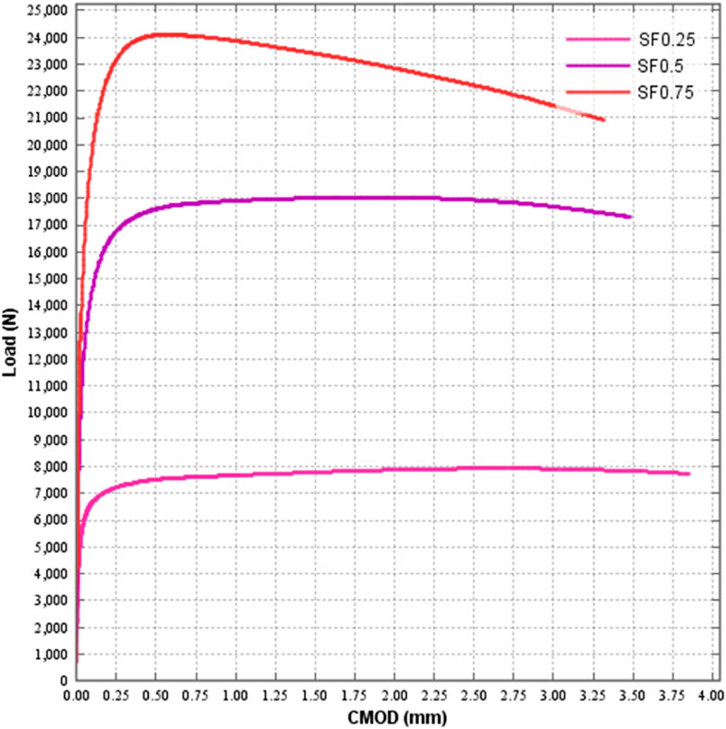
FIGURE 6. Load-CMOD curve of NLFEA of FRC beams.
It is evident from the picture that steel fibers have a significant effect on the load-carrying capacity of SFRC. SFRC with a steel ratio of 0.25% is 7.94 kN while for 0.5% and 0.75% steel fiber the peak load is 18 kN and 24 kN respectively. However, steel fibers have an adverse effect on the post peak curve of the load-CMOD. After the peak load for 0.25% and 0.5% steel fibers there is less loss in the ductility of the FRC material as compared to 0.75%. This may be attributed to the lack of proper distribution of steel fibers in a 0.75% ratio. Introducing steel fibers enhances the load-carrying capability of the FRC beams. By growing the proportion of steel fibers, the load-bearing capability of FRC beams experiences a substantial enhancement. The use of steel fibers with a concentration of 0.75% resulted in achieving an optimum load-carrying capability of 24 kN. However, once the ultimate load capability is reached, the rate of decline of the 0.75% steel fiber is steeper compared to the lesser proportion of steel fibers. According to (Wang et al., 2022), the inclusion of steel fibers in rubberized self-compacting concrete resulted in a significant increase in crack propagation after cracking.
3.2 Cohesive stress crack mouth opening displacement curve
The Figure 7 shows the tensile stress curve against the CMOD. As discussed in the load-deflection curve the steel fibers have a great impact on the tensile behaviour of the FRC material. The maximum tensile strength was obtained in the 0.75% fiber with 6.6MPa, while for 0.5% and 0.25% steel fiber ratio, the tensile stresses were recorded as 4.9 MPa and 1.6 MPa respectively. Similarly in the post-peak behavior of the FRC beams a brittle attitude has been observed in the higher percentages of the steel fibers. The introduction of steel fibre in FRC resulted in a better post-peak cumulative load for stress-CMOD behaviours. The FRC mixture with 0.75% steel fiber content exhibited the most favorable post-cracking characteristics among the other mixtures. This study showcased the beneficial impact of using steel fibre in enhancing the spread of cracks and the dissipation of energy in FRC. Due to their comparatively greater elastic modulus, the dispersed steel fibers may effectively prevent the occurrence of the first fracture when subjected to tensile stress in a mixture, hence enhancing their strength (Wang et al., 2020).
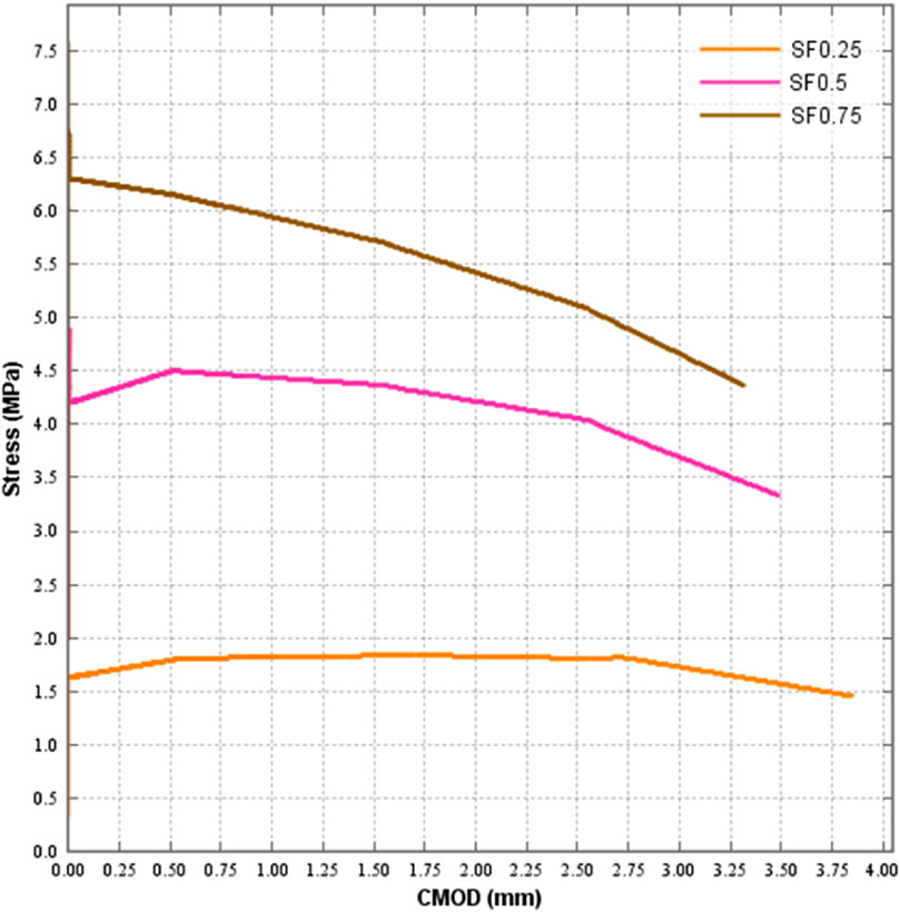
FIGURE 7. Stress-CMOD curve for FRC beams with steel fibers.
3.3 Crack width of fiber reinforced concrete beam
The effect of steel fibers on the crack width and crack propagation is shown in Figure 8. The addition of steel fibers in the FRC has positive impact. It can be seen that the crack width at the last step of NLFEA is less with 0.75% steel fiber as compared to 0.5% and 0.25%. This is due to the high tensile strength and ductility of steel fibers as compared to surrounding matrix in FRC. The use of steel fibres improves the FRC beams’ performance to support loads. Increasing the percentage of steel fibres significantly improves the overall ability of FRC beams to support loads. The best load-carrying capacity was attained by using steel fibres at a content of 0.75%. The rate of fall of the 0.75% steel fibre, in contrast to the smaller fraction of steel fibres, is greater after the ultimate load capacity is attained. Steel fibres were added to rubberized self-compacting concrete, and found that this significantly increased the crack’s ability to propagate once it cracked (Wang et al., 2022).
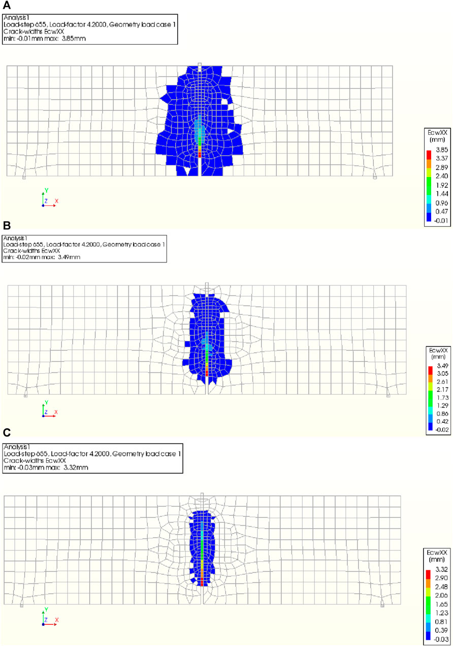
FIGURE 8. Crack width at the last step of NLFEA. (A) SF0.25, (B) SF0.5, and (C) SF0.75.
3.4 Fracture parameters of the fiber reinforced concrete beams
The fracture parameters of the FRC beams with varying percentages of the steel fibers are summarized in Table 4.
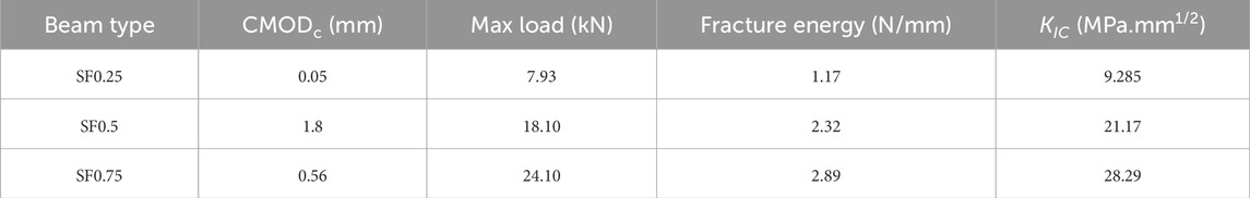
TABLE 4. Fractures parameters of FRC beam.
From Table 4 it can be observed that fracture energy of the FRC beams increases with the increase in steel fiber percentage. However, there is not much difference in fracture energy between 0.5% and 0.75%. Similar behaviour can be seen in the case of fracture toughness co-efficient. The fracture values reported for beams made of FRC with varying steel fiber concentrations are consolidated in Table 4. The KIC values were measured as 9.28 MPa mm1/2, 21.17 MPa mm1/2, and 28.29 MPa mm1/2 after 28 days of curing for FRC samples containing 0.25%, 0.5%, and 0.75% steel fibers, respectively. Furthermore, the inclusion of steel fiber resulted in an improvement in both the critical crack mouth opening displacement (CMODc) and the fracture energy (
4 Conclusion
This work presented a FEM modelling approach based on the experimental data to simulate the fracture behaviour of SFRC beams. The study thoroughly discusses the constitutive model of SFRC, mesh dependency on the analysis and finally the fracture parameters of SFRC beams.
1. The tension-softening function obtained from the experiment was integrated into the developed FEM model to predict load-carrying capacity and fracture behaviour parameters i.e., fracture energy and fracture toughness. The developed FEM model showed a good agreement with the experimental results.
2. Steel fibers significantly impact the load-carrying capacity of SFRC, with peak loads of 18 kN and 24 kN for 0.5% and 0.75% fibers respectively. However, steel fibers negatively affect the post-peak curve of load-CMOD, possibly due to improper fiber distribution.
3. The developed FEM models reveals that the use of steel fibers in FRC material significantly impacts its tensile behaviour. The maximum tensile strength was achieved with a 0.75% fiber content, with a brittle attitude observed in higher fiber percentages. The introduction of steel fibers improved tensile strength behaviour which ultimately improves the resistance against spread of cracks, and preventing fractures due to their greater elastic modulus.
4. Fracture energy and fracture toughness showed a similar trend and the maximum fracture energy of 2.89 N/mm at steel fiber ration of 0.75%. It is worth noting that for 0.50% and 0.75% of steel fiber the peak load, fracture energy and tensile strength showed a smaller improvement as compared to the 0.25% of steel fibers in FRC beam. This showed that with the further increase in steel fibers the effect of fibers may not be significant.
5 Future research
To enhance the study of fractures in SFRC using the FEM, it is suggested to investigate advanced material models and integrate nonlinear analyses to accurately represent the behaviour after cracking. Dynamic analysis may provide insight into the behaviour of SFRC under dynamic stress circumstances, whereas durability studies should evaluate its long-term performance, taking into account environmental considerations. Parametric research should methodically examine the influence of different components, and continuous validation using experimental data is essential for ensuring model fidelity. Conducting mesh sensitivity assessments, including Building Information Modelling (BIM), and establishing design standards can enhance the effectiveness and practicality of the applications. In addition, educational outreach efforts may facilitate the widespread sharing of information and the advancement of innovation in the field of SFRC applications, guaranteeing the creation of structures that are both safer and more long-lasting in the future.
Data availability statement
Publicly available datasets were analyzed in this study. This data can be found here: NA.
Author contributions
MS: Conceptualization, Methodology, Validation, Writing–original draft, Writing–review and editing. NB: Conceptualization, Data curation, Investigation, Methodology, Writing–original draft, Writing–review and editing. MoA: Data curation, Methodology, Validation, Visualization, Writing–review and editing. MaA: Data curation, Formal Analysis, Validation, Visualization, Writing–review and editing. TN: Conceptualization, Formal Analysis, Funding acquisition, Visualization, Writing–review and editing. YG: Data curation, Formal Analysis, Software, Validation, Visualization, Writing–review and editing. HA: Data curation, Methodology, Resources, Writing–review and editing.
Funding
The author(s) declare financial support was received for the research, authorship, and/or publication of this article. This study is supported via funding from Prince Sattam bin Abdulaziz University project number (PSAU/2023/R/1445).
Conflict of interest
The authors declare that the research was conducted in the absence of any commercial or financial relationships that could be construed as a potential conflict of interest.
Publisher’s note
All claims expressed in this article are solely those of the authors and do not necessarily represent those of their affiliated organizations, or those of the publisher, the editors and the reviewers. Any product that may be evaluated in this article, or claim that may be made by its manufacturer, is not guaranteed or endorsed by the publisher.
Abbreviations
FRC, Fibre-Reinforced Concrete; SFRC, Steel fibre-Reinforced Concrete; NLFEA, Non-Linear Finite Element Analysis.
References
Ai, D., Jiang, G., Lam, S. K., He, P., and Li, C. (2023). Computer vision framework for crack detection of civil infrastructure—a review. Eng. Appl. Artif. Intell. 117, 105478. doi:10.1016/j.engappai.2022.105478
Alava, M. J., Nukala, P. K. V. V., and Zapperi, S. (2006). Statistical models of fracture. Adv. Phys. 55, 349–476. doi:10.1080/00018730300741518
Amin, A., and Gilbert, R. I. (2019). Steel fiber-reinforced concrete beams—Part I: material characterization and in-service behavior. ACI Struct. J. 116, 101–111. doi:10.14359/51713288
Choi, W. C., Jung, K. Y., Jang, S. J., and Yun, H.Do (2019). The influence of steel fiber tensile strengths and aspect ratios on the fracture properties of high-strength concrete. Materials 12, 2105. doi:10.3390/MA12132105
Combrinck, R. (2012). Plastic shrinkage cracking in conventional and low volume fibre reinforced concrete. Doctoral dissertation, Stellenbosch: Stellenbosch University. Available at: http://hdl.handle.net/10019.1/71648.
Conforti, A., Zerbino, R., and Plizzari, G. A. (2019). Influence of steel, glass and polymer fibers on the cracking behavior of reinforced concrete beams under flexure. Struct. Concr. 20, 133–143. doi:10.1002/suco.201800079
DIANA (2023). “DIANA finite element analysis Release Notes Release 10.4.”. Available at: https://manuals.dianafea.com/d104/RelNot/RelNot (Accessed October 27, 2023).
Ding, Y., Li, D., Ma, Y., Liu, G., Song, S., Zhang, D., et al. (2021). Self-localization of the flexural cracks of fiber reinforced concrete beams. Constr. Build. Mater 302, 124364. doi:10.1016/j.conbuildmat.2021.124364
Di Prisco, M., Colombo, M., and Dozio, D. (2013). Fibre-reinforced concrete in fib Model Code 2010: principles, models and test validation. Struct. Concr. 14, 342–361. doi:10.1002/suco.201300021
Hollaway, L. L., and Leeming, M. B. (1999). Strengthening of reinforced concrete structures: using externally-bonded FRP composites in structural and civil engineering. Cambridge: Woodhead Publishing Limited. 327.
Jiao, D., Shi, C., Yuan, Q., An, X., Liu, Y., and Li, H. (2017). Effect of constituents on rheological properties of fresh concrete-A review. Cem. Concr. Compos 83, 146–159. doi:10.1016/j.cemconcomp.2017.07.016
Kiran, R., Teodoriu, C., Dadmohammadi, Y., Nygaard, R., Wood, D., Mokhtari, M., et al. (2017a). Identification and evaluation of well integrity and causes of failure of well integrity barriers (A review). J. Nat. Gas. Sci. Eng. 45, 511–526. doi:10.1016/j.jngse.2017.05.009
Maritz, J. L. (2012). An investigation into the use of low volume-fibre reinforced concrete for controlling plastic shrinkage cracking. Doctoral dissertation, Stellenbosch: Stellenbosch University. Available at: http://hdl.handle.net/10019.1/19983.
Merta, I., and Tschegg, E. K. (2013). Fracture energy of natural fibre reinforced concrete. Constr. Build. Mater 40, 991–997. doi:10.1016/j.conbuildmat.2012.11.060
Nallathambi, P., Karihaloo, B. L., and Raiss, M. E. (1987). Discussion: determination of specimen-size independent fracture toughness of plain concrete. Mag. Concr. Res. 39, 113–115. doi:10.1680/macr.1987.39.139.113
Rong, H., Dong, W., Zhao, X., and Zhou, X. (2021). Investigation on multi-cracks initiation and propagation of fiber reinforced concrete in restrained shrinkage ring tests. Theor. Appl. Fract. Mech. 111, 102856. doi:10.1016/j.tafmec.2020.102856
Safiuddin, M., Kaish, A. B. M. A., Woon, C. O., and Raman, S. N. (2018). Early-age cracking in concrete: causes, consequences, remedialmeasures, and recommendations. Appl. Sci. Switz. 8, 1730. doi:10.3390/app8101730
Seagraves, A., and Radovitzky, R. (2010). Advances in cohesive zone modeling of dynamic fracture. Dyn. Fail. Mater. Struct., 349–405. doi:10.1007/978-1-4419-0446-1_12
Standard 2023 Standard: method of test for load-displacement curve. - Google scholar Accessed: October. 27, 2023. Available at: https://scholar.google.com/scholar_lookup?title=Method+of+test+for+load-displacement+curve+of+fiber+reinforced+concrete+by+use+of+not
Tada, H., Paris, P. C., and Irwin, G. R. (1973). The stress analysis of cracks, 34. Handbook: Del Research Corporation.
Taheri, M., Barros, J. A. O., and Salehian, H. (2020). Integrated approach for the prediction of crack width and spacing in flexural FRC members with hybrid reinforcement. Eng. Struct. 209, 110208. doi:10.1016/j.engstruct.2020.110208
Tarabin, M., Leblouba, M., Barakat, S., and Zahri, M. (2023a). Experimental and probabilistic analysis of the crack propagation in fiber reinforced concrete. Eng. Fail Anal. 151, 107388. doi:10.1016/j.engfailanal.2023.107388
Thomas, J., and Ramaswamy, A. (2007). Mechanical properties of steel fiber-reinforced concrete. J. Mater. Civ. Eng. 19, 385–392. doi:10.1061/(asce)0899-1561(2007)19:5(385)
Tiberti, G., Minelli, F., and Plizzari, G. (2015). Cracking behavior in reinforced concrete members with steel fibers: a comprehensive experimental study. Cem. Concr. Res. 68, 24–34. doi:10.1016/j.cemconres.2014.10.011
Wang, J., Dai, Q., and Si, R. (2022). Experimental and numerical investigation of fracture behaviors of steel fiber–reinforced rubber self-compacting concrete. J. Mater. Civ. Eng. 34. doi:10.1061/(asce)mt.1943-5533.0004010
Wang, J., Dai, Q., Si, R., Ma, Y., and Guo, S. (2020). Fresh and mechanical performance and freeze-thaw durability of steel fiber-reinforced rubber self-compacting concrete (SRSCC). J. Clean. Prod. 277, 123180. doi:10.1016/j.jclepro.2020.123180
wikipedia (2022). Paris’ law. Available at: https://en.wikipedia.org/w/index.php?title=Paris%27_law&oldid=1111533679.
Yazici, Ş., Inan, G., and Tabak, V. (2007). Effect of aspect ratio and volume fraction of steel fiber on the mechanical properties of SFRC. Constr. Build. Mater 21, 1250–1253. doi:10.1016/j.conbuildmat.2006.05.025
Zhang, B., Bicanic, N., Pearce, C. J., and Balabanic, G. (2000). Residual fracture properties of normal- and high-strength concrete subject to elevated temperatures. Mag. Concr. Res. 52, 123–136. doi:10.1680/macr.2000.52.2.123
Zhang, P., Wang, C., Gao, Z., and Wang, F. (2023). A review on fracture properties of steel fiber reinforced concrete. J. Build. Eng. 67, 105975. doi:10.1016/j.jobe.2023.105975
Keywords: steel fiber, fibre-reinforced concrete, fracture analysis, fracture energy, Finite element method modelling
Citation: Shams MA, Bheel N, Ali M, Ahmad M, Najeh T, Gamil Y, Almujibah HR and Benjeddou O (2024) Fracture analysis of steel fibre-reinforced concrete using Finite element method modeling. Front. Mater. 11:1355351. doi: 10.3389/fmats.2024.1355351
Received: 13 December 2023; Accepted: 29 January 2024;
Published: 14 February 2024.
Edited by:
Lu Ke, Guangxi University, ChinaReviewed by:
Pengfei Ren, Shandong Jianzhu University, ChinaJianchao Zhang, Dongguan University of Technology, China
Copyright © 2024 Shams, Bheel, Ali, Ahmad, Najeh, Gamil, Almujibah and Benjeddou. This is an open-access article distributed under the terms of the Creative Commons Attribution License (CC BY). The use, distribution or reproduction in other forums is permitted, provided the original author(s) and the copyright owner(s) are credited and that the original publication in this journal is cited, in accordance with accepted academic practice. No use, distribution or reproduction is permitted which does not comply with these terms.
*Correspondence: Naraindas Bheel, bmFyYWluZGFzMDRAZ21haWwuY29t; Taoufik Najeh, dGFvdWZpay5uYWplaEBsdHUuc2U=