 Lubin Wang
 Wenliang Chen3
- 1Key Laboratory of Pressure System and Safety, Ministry of Education, East China University of Science and Technology, Shanghai, China
- 2Innovation Center for High-end Equipment and Intelligence Manufacturing Technology, Ningbo Institute of Dalian University of Technology, Ningbo, China
- 3Hangzhou Vocational and Technical College, Hangzhou, China
- 4Design and Development Department, Ningbo Huaxiang Automotive Technology Co., Ltd., Ningbo, China
The thermal failure mechanism of sliding composite leaf springs (SCLSs) is examined in this research. Bench fatigue testing is used in the experimental investigation of the thermal failure temperature and mode. The findings demonstrate that after 20 min, when the temperature reaches the glass transition temperature, cracks start to form around the bolt hole of the composite body. The findings from bench experiments indicate that thermal fatigue failure of SCLS can be divided into three main forms: delamination failure of the resin-rich layer, the resin-fiber interface, and fibre pull-out failure. The utilization of finite element simulation has demonstrated that when subjected to thermal load, the leaf spring’s internal defects can lead to localized stress concentration. The structure of the spring end is optimized using the insulating panel scheme and the metal joint scheme. The thermal fatigue issue with SCLS is best addressed by the heat dissipation approach, according to bench tests.
1 Introduction
Compared with traditional metal materials, composite materials have superior properties such as high strength, stiffness, high strength-and-stiffness-to-weight ratios, and great corrosion resistance (Sancaktar and Gratton, 1999). They have been widely used in aerospace, automotive, shipbuilding, engineering construction, sports equipment, and other fields. In the automobile industry, the leaf spring as an essential part of automobile suspension has the function of transmission and guidance, and it is the critical part to support the main body of the automobile. The main current leaf spring in the market is made of steel which accounts for about 5%–7% of the body weight. Recently, composite structures have been increasingly used to replace conventional metallic components for saving weight and increasing energy efficiency. Compared with traditional steel leaf springs, composite leaf springs (CLSs) with service cycle, sound noise reduction, strong design ability, and good safety fracture (Shamsaei and Rezaei, 2004; Kueh and Faris, 2012; Soner et al., 2012; Ke et al., 2019). It is reported that the CLS can replace the traditional steel leaf spring and have better fatigue performance (Tadesse and Fatoba, 2022a; Tadesse and Fatoba, 2022b). According to the installation mode, CLSs can be divided into horizontal and vertical springs. The longitudinal spring includes an eye-end spring and a sliding spring. Sliding springs are wildly used in heavy trucks and semi-trailers. In practical application, SCLSs are often subjected to complex and long-term thermal stimulation. Thermal stress concentration or thermal strain increase caused by drastic temperature change is one of the main reasons, leading to structural failure of composite materials (Rao et al., 2008; Raghava et al., 2015). Therefore, the thermal failure mechanisms of CLS need further exploration.
There have been a large number of studies on the structural failure of CLS under ultimate strength and periodic fatigue. It has reported that the fatigue reliability of a CLS can meet the loading requirements of vehicles (Lo et al., 1987). Composite leaf spring optimization (Chen, 2001), fatigue life prediction (Shankar and Vijayarangan, 2006), and joint reliability (Pakdil et al., 2007) have been studied by several scholars. For instance, (Shokrieh and Rezaei, 2003), employed finite element method to optimize a CLS with minimum weight to carry given force without failure. (Hou et al., 2005). studied the delamination failure of three designs of eye-end attachment for CLS. The fatigue life of CLS was improved based on the ply scheme design optimization (Qian et al., 2017). The modal flexibility and modal curvature methods were used to conduct the failure analysis of composite mono leaf spring (Jamadar et al., 2018). Rajesh (Rajesh and Bhaskar, 2014; Rajesh et al., 2016) investigated the performance of leaf springs made of composite materials subjected to low-frequency impact loading, which simulates the vehicle dynamics due to load tire interactions. (Papacz et al., 2014). found that the main failure mode of CLS is delamination fatigue, and the fatigue performance of composite spring is better than that of steel leaf spring. (Gort et al., 2021). observed that a significant discrepancy between the transverse tensile strength in the out-of-plane direction and the in-plane direction can lead to reduced resistance to delamination, hence increasing the potential of failure in the CLS. (Oh and Choi, 2014). focused on the static behaviors of the leaf spring due to the material composition and its fiber orientation. It was found that damage first occurred along the edge of the leaf spring owing to the shear stresses. (Fabian et al., 2019). developed a simplified testing program that is able to reproduce the damage and the fatigue behavior which occurs in composite components. (Kumar et al., 2023). embedded a self-healing agent dicyclopentadiene in CLS, identified that the addition of microcapsule-based healing substituents increases the load-carrying and fatigue capacity of CLS.
Nevertheless, fewer research concerning the thermal failure of CLSs, particularly in SCLSs. Compared to the eye-end leaf spring, the SCLS inevitably generates a significant quantity of heat at its end due to the working conditions. To mitigate safety risks arising from thermal fatigue at elevated temperatures and enhance fatigue durability, it is imperative to investigate the thermal failure mechanism of SCLSs.
This article provides an in-depth review of thermal fatigue analysis and structural optimization of SCLS, distinguishing it from previous research articles in this field. It comprehensively evaluates the design and verification process of the complete SCLS, analyzes the causes of thermal failure at the spring end, and provides effective improvement ideas. In this study, the thermal failure modes of SCLSs were investigated experimentally by bench fatigue test. The temperature changes of the spring end were measured and evaluated. In Section 2, the structural designs including the structural parameters, stacking sequence, material properties and loading information of SCLS are provided. Section 3 presents experimental methods for thermal fatigue analysis. In Section 4, the heat transfer pathways and failure modes of spring body subjected to bench testing are discussed. In Section 5, investigates the distribution of the temperature field and the underlying causes of failure in spring end under simulated conditions. In Section 6, two different structural improvement schemes are proposed. The conclusions are given in the final section of this paper.
2 Structural design and load condition analysis
2.1 Structural design
The common structure of the sliding spring is shown in Figure 1. The sliding spring and eye-end spring have the same design in the clamping part. The gasket and hook, usually made of metal are assembled at the end of the spring. The gasket is mainly responsible for the force transfer between the spring and the support; the hook plays a role in preventing the composite spring from separating from the suspension under extreme conditions. Bolts connect the composite body, gasket, and hook.
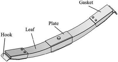
FIGURE 1. A sliding composite leaf spring.
Table 1 contains the primary structural characteristics of the sliding leaf spring. The structural design of leaf springs primarily considers the 'equal stress beam’ features, the fiber volume fraction, and the material usage rate. Metal springs make up most sliding leaf springs, while CLSs are sometimes used in their place. Comparable to metal springs, CLSs operate under similar conditions.
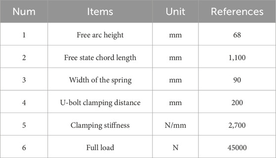
TABLE 1. Main design parameters of SCLS.
Based on the traditional parabolic spring design theory (Lo et al., 1987), the spring body size of a composite spring is preliminarily designed and the basic frame is provided for the design of the layering scheme. Figure 2 shows the dimension parameters of the parabolic spring in the flattening state. According to the CAD drawing of the provided leaf spring, the dimension parameters were measured and recorded in Table 2.
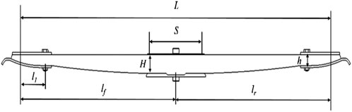
FIGURE 2. A schematic illustration of a parabolic leaf spring in flat status.
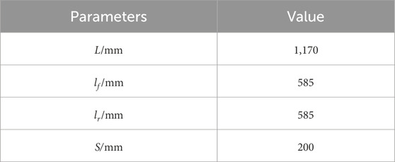
TABLE 2. Structural parameters of composite leaf spring.
If l1 = 100 mm, according to the relevant design theory, the thickness of the parabola end in the front and back sections is calculated, respectively (Yang et al., 2019).
As lf is close to lr, in order to ensure that the thickness h of the front and back part of the plate spring becomes the same, it can be considered that
The first half stiffness Kf, the second half stiffness Kr and the overall stiffness K of the parabolic spring are determined respectively.
In this formula, E is the elastic modulus of the material, ξ is the correction coefficient, which is 0.92 (Wang et al., 2023) and I0 is the moment of inertia of the section. δ and λ are regarded as coefficients.
Substituting K = 2700N/mm into Eq. 5 and combining Eqs 1–4, the following data can be obtained, as H ≈ 56mm, and h ≈ 25 mm. Therefore, 56mm and 25 mm are selected respectively for the thickness of the middle and end of the CLS.
As the free arc height of the steel leaf spring
2.2 Layer design
The benefits of high strength and high modulus of glass fiber dimension can be completely used when the layering orientation is 0° (Ferreira et al., 1999a). Therefore, the primary stacking direction of the CLS is selected to be 0°. To assure the joint strength of the CLS, a specific percentage of 45° lamination is fixed at the hole of the spring end.
The thickness of uniaxial E glass fiber/epoxy laminates with 58.0% fiber volume content is 0.81 mm, so the total number of laminates is 56/0.81≈69. The width of each ply is 90 mm, the length of each ply can be determined by the outer profile of the parabolic section of the parabolic spring. Through the above method, the preliminary laminate scheme of the CLS can be established.
CPD (Composite Design) module of CATIA software was used to design the lamination of the CLS. The final lamination diagram of the leaf spring is shown in Figure 3. The number of lamination layers in the middle of the leaf spring is 73, among which 4 layers are boss lamination. The red lines represent the layering with ±45°, the green lines represent the layering with 0°. It is shown that there are 23 layers with full-length lamination remarked as ‘○’ and 50 layers with short lamination, denoted by the symbol ‘△’.
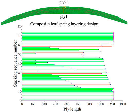
FIGURE 3. Stacking sequence of sliding composite leaf spring.
2.3 Material parameters
The SCLS consists of a core composite body accompanied by several metal embellishments. The combined spring body refers to a construction method wherein glass fiber and epoxy resin are molded together in a procedure that results in a structure with uniform width but varied thickness. The cover plate, gasket, and hook are fabricated using the metal 40Cr. The glass transition temperature (Tg Point) of epoxy resin is reported to be 115°C. The material specifications of the composite spring are presented in Tables 3, 4.
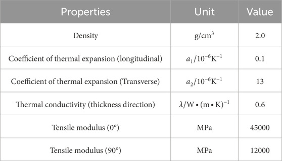
TABLE 3. Material properties of composite.
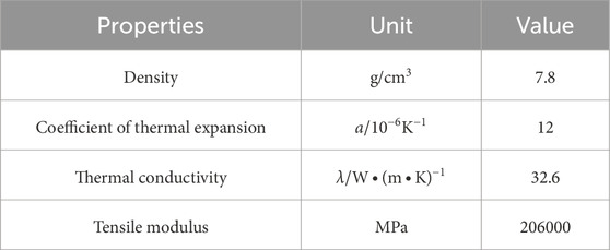
TABLE 4. Material properties of 40Cr.
2.4 Load condition
The main load condition of a SCLS has been presented. The load scenarios consist of vertical loading and fatigue loading. The load conditions being referenced are displayed in Table 5. The X-axis is defined as the longitudinal axis of the body, which corresponds to its length. The Y-axis is associated with the horizontal direction, which represents the breadth of the body. The Z-axis denotes the vertical orientation, signifying the vertical dimension of the body, specifically its height. Furthermore, the symbol P represents the cumulative force applied by the vehicle. Heat fatigue is identified as the principal factor contributing to the occurrence of spring failure.
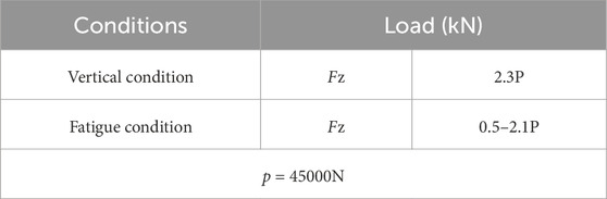
TABLE 5. Load requirements of spring.
3 Experimental investigations
3.1 Specimen fabrication
The production of composite bodies involves the utilization of the high-pressure resin transfer molding (HP-RTM) process for injection molding. Metal components are manufactured by the processes of sheet stamping and wire cutting molding. The composite spring located between the body end and metal gasket is assembled using glue and bolt connections. The central region of the composite body contains a clamping area that is affixed to the guard plate using glue. To mitigate the impact of the bolt hole located at the spring end, a hinged bolt mechanism is implemented. Figure 4 depicts the manufacturing process flow chart for the SCLS.
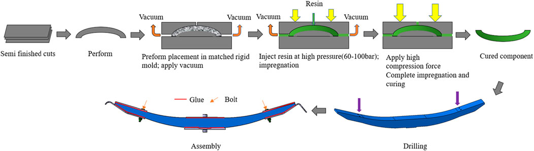
FIGURE 4. Manufacturing process flow chart of sliding composite leaf spring.
3.2 Bench test
The process of spring verification typically involves three distinct stages: the bench test, commonly referred to as a standard test, the system bench test, and the road test. The bench test refers to a specific type of mechanical evaluation known as the single-axis spring three-point bending test. This test is conducted to assess the stiffness and fatigue characteristics of an individual spring. The system bench is commonly employed as a two-axis or three-axis linkage test for the assessment of the balancing and coordination performance of multi-axis springs. The primary objective of a road test is to assess the performance of a spring component under a range of challenging road conditions. When comparing the system bench test and road test, it is seen that the loading conditions in the uniaxial bench test are typically more rigorous. This test can provide a more accurate representation of the heat carrying capacity of the spring.
The bench test of the CLS is shown in Figure 5. A portion of the axle and frame components are utilized as experimental instruments to replicate the spring’s motion in the actual automotive environment. The central section of the spring is affixed to the axle fixture using U-bolts, while the upper section of the axle fixture is connected to the loading actuator of the testing machine. The axle and loading actuator are interconnected by means of a pin. The spring’s ends is attached to the frame, and the structure connects to the axle via a dampening rod, aligning with the practical configuration of the vehicle. The experimental platform is secured to the frame using bolts. The equipment of the bench test is a servo-hydraulic system. A sensor has been mounted on the actuator. The sensor will collect the load and displacement experienced by the spring as it undergoes movement, and subsequently transmit the data to the control computer.
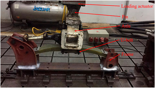
FIGURE 5. Bench test of sliding composite leaf spring.
During the experimental procedure, the individual temporarily in charge applies a sinusoidal displacement load to the spring, with a vertical amplitude of 22.5 mm (22.5kN–94.5 kN). The spring terminations exhibit slippage along the longitudinal axis of the frame. The thermal energy in the spring is produced as a result of the frictional forces between the gasket located at the spring end and the frame. Typically, the loading frequency for a conventional bench test ranges from 0.5 to 1 Hz. To examine the temperature range and failure mechanism of the spring, the test frequency has been elevated to 1.5 Hz with the intention of expediting the testing procedure. The number of samples for the experiment was six.
4 Result and discussion
4.1 Temperature feedback
As shown in Figure 6, a total of six temperature monitoring sites have been strategically placed on both the left and right sides of the composite spring end. There are two locations, denoted as L3 and R3, located at the ends of the leaf spring. The remaining points, L1, R1, L2, and R2, are situated around the spring bolt hole near the gasket placement. The temperature measuring locations are situated within the composite body. There are two primary devices for measuring the spring temperature. One is to add a K-type thermocouple wire in composite body, while producing the springs and insert a thermometer (HY101) for measurement during the experiment. Another method is to use an infrared thermometer (FLUKE-F39) to measure the surface temperature of the composite body. In order to provide accurate measurements, it is imperative that the infrared thermometer is positioned perpendicular to the surface being measured. Prior to utilizing measuring instruments, it is important to calibrate the equipment. The proposed approach involves utilizing the specified equipment to perform the calibration of water at temperatures of 20°C and 100°C. The measures denoted as L1, L2, R1, and R2 are associated with infrared data, while L3 and R3 are indicative of thermocouple readings.
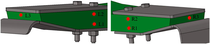
FIGURE 6. Temperature measuring point of CLS.
Figure 7 illustrates the temperature fluctuations seen at each measurement location throughout a 2-h period, with the ambient temperature maintained at 27°C. It is evident that the temperatures recorded at the measurement spots on the right side exhibit a notable increase compared to those on the left side. Within the framework of the bench system, the left support is interconnected with a pull rod. In this experiment, it is observed that the displacement of movement on the left side of the spring is comparatively smaller in magnitude when compared to the displacement on the right side. The coefficient of friction between the gasket plate of the left half spring and the support is lower compared to the right side. The temperature at each measuring point exhibits an upward trend after 60 min. If no cooling measures are used, the temperature at the termination point of the composite body (R3) can reach a maximum of 140°C after a duration of 60 min. At the 80-min mark, the temperature of R3 achieves its peak value of 180°C. Subsequently, the temperature gradually falls and approaches a state of stability. By the 120-min mark, the temperature has decreased to 160°C. The temperature at the L3 point exhibits a maximum value of 90°C at the 60-min mark, followed by a gradual decrease from 90°C to 60°C between the 60th and 100th minute. Subsequently, the temperature stabilizes. The data reveals that the temperatures of R2 and L2 are comparatively higher than those of R1 and L1, respectively. One possible explanation is that the proximity of R2 and L2 to the friction surface is greater compared to R1 and L1.
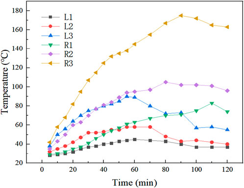
FIGURE 7. Temperature variation of each temperature measurement point.
The number of fatigue cycles of CLSs exhibits a positive correlation with time. Based on the experimental loading frequency, it can be determined that the fatigue loading of CLSs occurs at a rate of 1.5 times per second. Figure 7 demonstrates that with a loading frequency of 3,600, the temperature at R3 surpasses the Tg point. At a loading cycle of 8,000, the temperature at the spring end reaches its maximum value. After 8000 cycles, the temperature of the spring reaches a state of stability.
4.2 Heat conduction path
The bench test is a device used for experimental purposes in a controlled laboratory setting. In the context of heat transfer, the concept of "spring” primarily encompasses the elements of spring end friction and frame dynamics during the motion (Ferreira et al., 1999b). The thermal conductivity of resin is significantly lower compared to that of metal, resulting in a relatively poor efficiency of heat transmission within the composite body. The heat transfer pathway of the composite body can be simplified into two distinct paths, as seen in Figure 8. There are two primary mechanisms involved in the transmission of the gasket’s thermal energy. Firstly, heat conduction allows for direct movement of heat from the gasket to the bottom of the spring body. Secondly, the gasket’s thermal energy is transferred through a series of steps: from the gasket to the bolt, then from the bolt to the hook, and finally from the hook to the composite body, as depicted in Figure 8. The heat transfer through the first route is significantly greater than that through the second channel due to the bigger heat dissipation area in the second passage. Additionally, there is a notable heat loss during the transmission process.
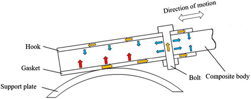
FIGURE 8. Heat conduction diagram of the composite spring end.
4.3 Failure mode
The delamination failure of a CLS occurs when the temperature in spring surpasses the glass transition temperature (Tg) of the resin. This increase in temperature causes a significant reduction in the binding force between the resin and the fiber, resulting in their separation. Figure 9 illustrates the failure patterns seen at the spring end during the bench test. After a duration of 60 min, observable changes were noted on the right extremity of the spring, characterized by a whitish discoloration and the emergence of delicate fissures. After a duration of 90 min, the initial fracture underwent expansion, subsequently leading to the emergence of a secondary crack positioned above the primary breach. After a duration of 120 min, a fracture initially emerged at the center of the spring, followed by the delamination of the spring’s perforation, leading to the premature termination of the test.
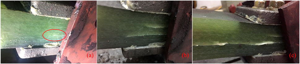
FIGURE 9. Failure picture of composite spring during bench test: (A) Cracks appear; (B) Cracks extension; (C) Cracks through, delamination. Sequence of crack expansion: (A–C).
The presence of cracks results in a reduction in the stiffness of the right side of the spring, leading to an inconsistency in the stiffness between the left and right sides. During the fatigue loading process, there is an observable increase in displacement on the right side of the spring, while the displacement on the left side decreases. Consequently, this leads to a heightened level of friction on the right side. As the level of friction decreases on the left side, there is a corresponding decrease in temperature. The gradual separation of the resin and fiber bonding surface of the composite body is caused by the increase in temperature on the right side of the spring. Ultimately, this leads to the interlayer stress at the termination of the spring surpassing the material’s limit, causing the crack to propagate from the termination to the midpoint of the spring. Based on the curve depicted in Figure 7, it can be inferred that if the temperature surpasses the glass transition temperature (Tg point) of the resin for 20 min, noticeable cracks will appear on the surface of the spring, equal to 5,400 fatigue cycles. During the loading cycles ranging from 5,400 to 8,100, the cracks in the spring exhibited rapid expansion. When it reached 8,100, the process of crack propagation achieved a stable state.
According to the test, the first crack of the spring is located near the bolt hole of the composite body. The generation and evolution of damage is a highly complex problem. Delamination generally expands from small to significant gaps and develops from single to multiple cracks. The crack growth of the composite body is also related to the fiber orientation. The damage usually expands first in the longitudinal direction of the fiber and then transverse, as shown in Figure 10. Figure 10A–C shows a failure process of the spring, from intact condition (a) to the appearance of cracks (b), and finally to the delamination failure(c).
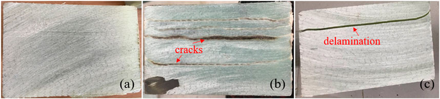
FIGURE 10. Prediction of the crack propagation path of the composite body, (A–C) shows the failure process of the spring.
The composite leaf at the bolt hole is prone to crack, mainly due to the interruption of continuous fiber at the bolt hole. In drilling the composite body, it is inevitable to cause separation between resin and fiber and even small cracks. These fine cracks are easy to propagate under the interaction of heat and stress over a long period. The main reason is that the heat flow is mainly distributed on the fiber, and the temperature distribution and heat flow transmission path depend on the fiber orientation. The fiber with high thermal conductivity will transfer some of its heat to the surrounding resin with low thermal conductivity. The closer it is to the fiber, the higher the resin temperature. In the in-plane direction, temperature and heat flow are traditionally fastest along the fiber direction perpendicular to the heat source (Subramanian and Senthilvelan, 2011).
The spring end failures are a result of interlayer and in-plane failures combined. The experiments’ typical failure types are shown in Figure 11, where the springs’ two separate sections are represented by the numbers and numbers’ following delamination failures. The illustration shows internal delamination of the resin layer at number 1, delamination at the resin-fiber contacts at number 2 and 3, and internal delamination of the fibers at number 4. Based on the observed failure morphology of the composite leaf spring, the multilayer failure of the spring may be classified into three distinct types. Mode I refers to the occurrence of delamination failure in the resin-rich layer, while Mode II pertains to the delamination failure at the interface between the fiber and resin layers; Mode III signifies the failure resulting from the separation of fibres.
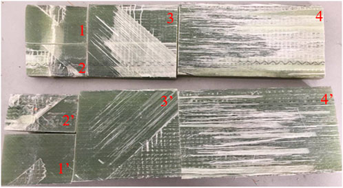
FIGURE 11. A photograph depicting the failure of composite leaf spring: Mode I (1–1′), Mode II (2–2′, 3–3′), Mode III (4–4′).
5 Finite element simulation
5.1 Two-dimensional model
The leaf spring’s ultimate state (Figure 11) shows that there are three primary failure modes in the length direction (x-axis). Finite element simulation is used to evaluate the causes of loss to gain a better understanding of the failure mechanisms. The ideal situation is for the resin to completely permeate the fibers, perfectly integrating the qualities of both materials. On the other hand, excess resin frequently accumulates between layers in CLSs, and the resin frequently needs to penetrate the fibers completely. In a single layer of leaf springs, the resin and fibers are separated at a 1:1 ratio to provide a more thorough analysis of the impact of temperature on the resin and fibers. Both the fibers and the resin have a thickness of 0.4 mm. As seen in Figures 12A, A simplified model with a length of 12 mm and a width of 3.6 mm is employed for the analysis. The resin layer is represented by grey, while the fiber layer is represented by black, as seen in Figure 12. The model’s ambient temperature is set to 27°C, its six degrees of freedom are restricted at the AD end, and a section located 4.5 mm from the B end is subjected to a 180°C temperature load (AB section). Section AD is classified as a thermally insulating interface, while Sections AB, BC, and CD are established as heat exchange interfaces with a convective heat transfer coefficient (fc) of 10
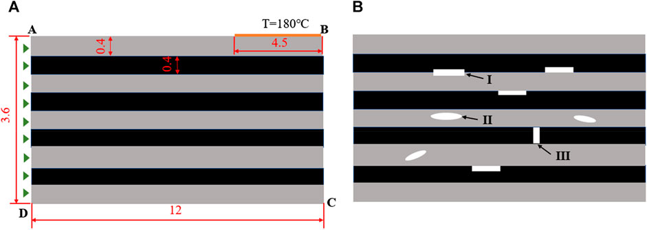
FIGURE 12. Simplified FEA model for 2D thermal displacement coupling analysis: (A) ideal model; (B) model with defects.
Figure 12B illustrates the defects observed in the resin and fiber layers, as depicted in Figure 12A. These defects can be attributed to the gaps that arise during the combination of resin and fiber in the injection molding procedure. The defects exhibit a random distribution in terms of their size and shape. The defect types labelled as I, II, and III in Figure 11 correspond to the three distinct failure modes. The analysis of the structure involves the utilization of the steady-state thermally-displacement coupled model. The specific element type employed is the 4-node thermally coupled doubly curved shell (S4RT) with reduced integration and hourglass control. The mean element size measures 0.03 mm, whereas the mesh was employed to enclose the faults with a resolution of 0.01 mm. The numerical simulations were performed utilizing the commercially available program ABAQUS, version 6.14-1. The fibre material exhibited a tensile modulus of 73 GPa, a coefficient of thermal expansion of
Figure 13 presents the comparative simulation outcomes pertaining to the displacement and temperature fields obtained from the thermal displacement coupling study of both the ideal model and the model incorporating flaws. The model has a maximum movement of 0.017 mm. The highest and lowest temperatures recorded are 178.2°C and 98.6°C, correspondingly. The largest displacement observed in the experiment is 0.019 mm, whereas the highest and lowest temperatures recorded are 179.2°C and 118.8°C, respectively. The analytical results pertaining to displacement and temperature of the model with defects exhibit a higher degree of significance in comparison to those of the ideal model. The primary cause for the significant displacement observed in the model with defects can be attributed to the reduced effective modulus resulting from the presence of defects. This reduction in effective modulus subsequently weakens the stiffness of the model, hence leading to an increase in displacement (Maa and Cheng, 2002). The elevated temperature can be attributed to the heightened contact thermal resistance in the model due to the existence of defects. This impedes the internal heat transfer process, leading to the buildup of heat within the interior that cannot be effectively carried to the top surface (Bai et al., 2011).
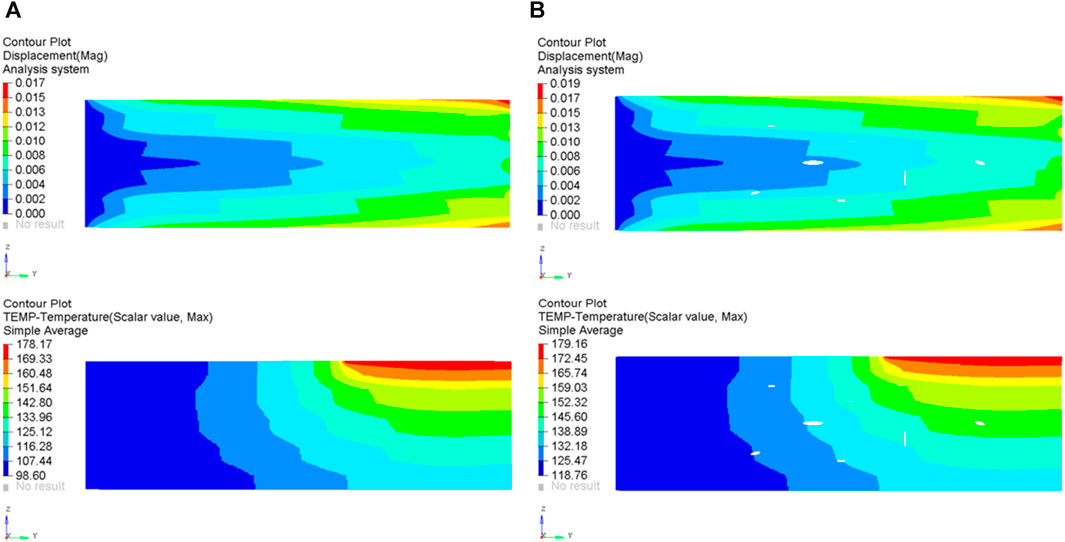
FIGURE 13. Displacement and temperature results of two-dimensional thermal displacement coupling analysis.
Typically, the main factors contributing to the failure of CLSs are associated with delamination failure, resulting from the growth of cracks along the longitudinal direction. This failure mechanism is primarily influenced by the tensile and compressive stresses experienced in the x-axis, specifically the stresses in the S11 direction (Chen, 2001). The variable S11_T represents the tensile stress along the longitudinal direction, while S11_T_Max represents the largest tensile stress in the same direction. Similarly, S11_C denotes the compressive stress along the S11 direction, and S11_C_Max indicates the maximum compressive stress in the S11 direction. A comparison between Figures 14A, B demonstrates that the presence of defects in the model leads to a notable rise in the S11_T_Max and S11_C_Max values, with respective increments of 97.2% and 89.3%. Upon examination of the stress distribution surrounding a common flaw, it is observed that defect A is associated with failure mode I, defect B is associated with failure mode III, and defect C is associated with failure mode II. Defect A is situated at the boundary between the resin layer and the fibre layer, and its occurrence is frequently attributed to the folding and distortion of the fibres during the process of fibre placement. When a fault occurs specifically at the interface between the fibres and the resin, the S11 directional stresses increase towards the fibre layer. This can be attributed to the substantial difference in modulus between the fibre layer and the resin layer. Additionally, when subjected to loading, the fibre layer primarily bears the load. The maximum stress in the S11_C direction for defect B is measured to be 45.7 MPa, while the maximum stress in the S11_T direction is found to be 8.9 MPa. It has been shown that when the orientation of the defect is perpendicular to the longitudinal direction, the S11 stress component in the compressive direction is significantly higher than that in the tensile direction. This situation is diametrically opposed when the defect’s approach aligns with the length direction (defect C). Upon examination of defects A, B, and C, it becomes evident that the presence of stress concentration phenomena surrounding these defects is apparent when the laminate is exposed to temperature loads. This observation suggests that temperature loads have the potential to expedite the initiation and propagation of cracks.
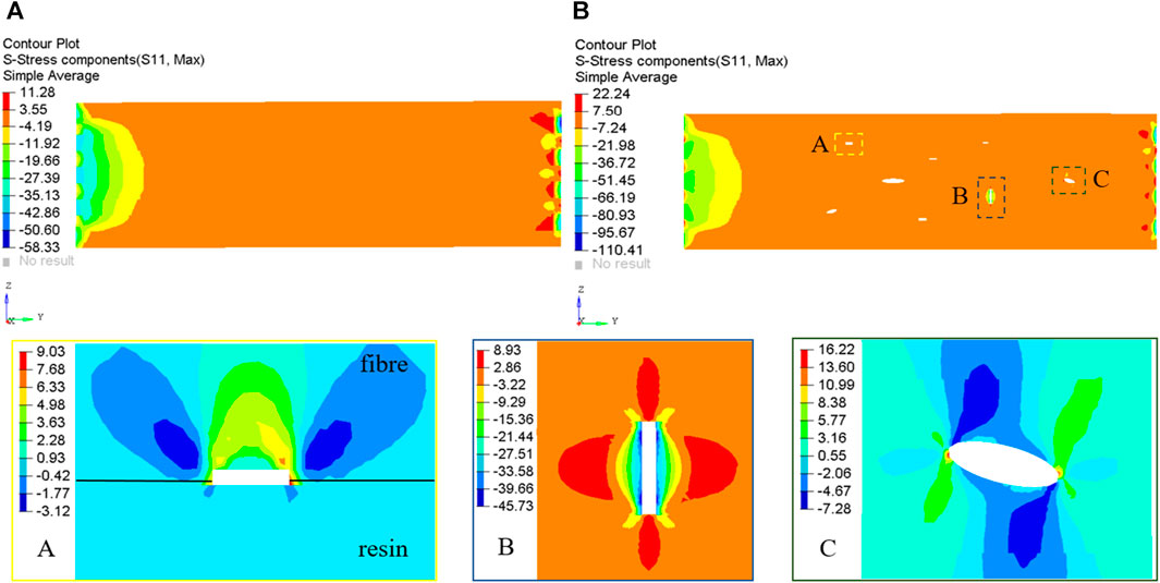
FIGURE 14. Stress Analysis Results in S22 Direction: (A) ideal model; (B) model with defects.
The primary method employed in the production of CLSs involves a sequential procedure of fibre lamination and subsequent injection of resin. The presence of defects in the manufacturing process of leaf springs is an inevitable consequence of the numerous layers involved. These defects can only be initially assessed qualitatively through experimental observation (Figures 9–11) and simulation analysis (Figures 12–14). The purpose of these assessments is to evaluate the impact of temperature on the failure of CLSs, as well as on the initiation and propagation of cracks. Quantitative analysis may present difficulties due to the intricate character of the process and the inherent uncertainty related to these defects.
5.2 Three-dimensional model
The ABAQUS software will be utilized to do a heat conduction analysis on the spring end (right side). The measurement and calculation of heat flow rate pose challenges due to the generation of heat through friction throughout the experimental process. Consequently, the heat source is simplified as an isothermal wall surface, with the temperature in the friction contact area of the spring end being set at the maximum failure temperature of 180 °C, as shown in Figure 15A, The loading area is the friction area of the experiment, with a width of 40 mm. The ambient temperature is adjusted to 27°C. Since the heat transfer at the spring end is mainly through thermal conduction, the influence of thermal radiation is ignored during the analysis, and the analysis type is steady-state thermal analysis. During the analysis, it is assumed that there is complete contact between the metal cover plate and the spring body. The contact thermal resistance between each component is disregarded. The selection of the fc between the spring end and air is close to and slightly larger than the range of natural air convective coefficient 5–25
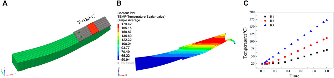
FIGURE 15. Three-dimensional FEA model and results of composite leaf spring thermal analysis: (A) FEA model; (B) Overall temperature distribution; (C) R1, R2, R3 point temperature curve.
The findings of the analysis are shown in Figure 15C. The region of elevated temperature is mostly localized in the vicinity external to the zone of friction, whereas the temperature at the location of the bolt is comparatively lower. When the fc of the spring body is set to 10
6 Structure optimization and verification
6.1 Heat-resistant plate scheme
Based on the preceding discourse, it is suggested that the incorporation of an insulating panel between the metal gasket and the composite body serves the purpose of mitigating high temperatures at the spring end, hence impeding heat transfer. The primary constituent of the insulating panel is mica. In this study, three different plans have been proposed for enhancing the existing system. Plan 1 (P1) involves the addition of a comprehensive discussion, as depicted in Figure 16A. Plan 2 (P2) suggests the incorporation of a panel with slots, as illustrated in Figure 16B. Lastly, Plan 3 (P3) proposes the integration of two insulating panels with spaces in the cross direction, as demonstrated in Figure 16C. The primary objective of employing slotting techniques is to enhance the surface area available for heat dissipation at the spring end. The bench test was conducted to evaluate the three systems, and the resulting temperature variation at the R3 point was documented. The test findings are depicted in Figure 17, wherein the original denotes the original structural arrangement. The findings indicate that the augmentation of the insulating panel contributes to the enhancement of the spring’s fatigue life. The introduction of P1, P2, and P3 has resulted in a significant improvement in the heat-resistant lifespan of the leaf spring. Specifically, the lifespan has increased from the initial duration of 120 min–140, 160, and 200 min, respectively. Nevertheless, the inclusion of a heat-resistant plate did not result in a decrease in the temperature of the spring end; rather, it led to an increase in temperature. The primary factor contributing to this outcome was the inadequate thermal conductivity of the heat-resistant container. The material has the ability to absorb and retain thermal energy, although its thermal storage capacity is constrained. Over the course of time, the thermal energy collected by the insulating panel will gradually be transmitted to the composite body. Therefore, incorporating a heat-resistant plate is not a viable approach.
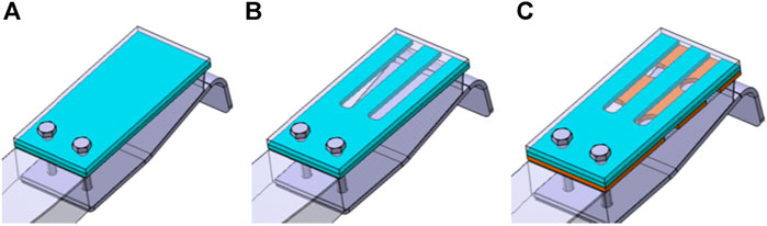
FIGURE 16. Optimization scheme of heat-resistant plate: (A) a whole plate; (B) a plate with slots; (C) two plates with cross-direction slots.
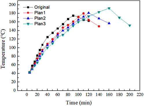
FIGURE 17. Temperature variation of heat-resistant plate scheme at R3 point.
6.2 Metal joint scheme
Based on the conjecture surrounding the thermal failure and heat conduction mechanism of the SCLS, it is imperative to position the spring body at a considerable distance from the heat source in order to enhance its thermal fatigue durability. The focus should be on heat dissipation rather than heat insulation. The redesign of the spring end is implemented with this concept. To optimize the performance of the CLS, it is recommended to relocate the bolt hole towards the innermost position, thereby increasing the distance between the friction region of the spring and the frame.
The joint configuration illustrated in Figure 18A is employed in the optimized termination of the CLS. The bolt-hole of the spring would be shifted inward to maximize the distance from the friction area. The joint configuration depicted in Figure 13A is employed in the optimized spring end. A specific space is intentionally maintained between the composite termination and the joint configuration to optimize the thermal dissipation at the spring termination. The temperature distribution findings of the joint scheme are depicted in Figure 18B for a fc of 10
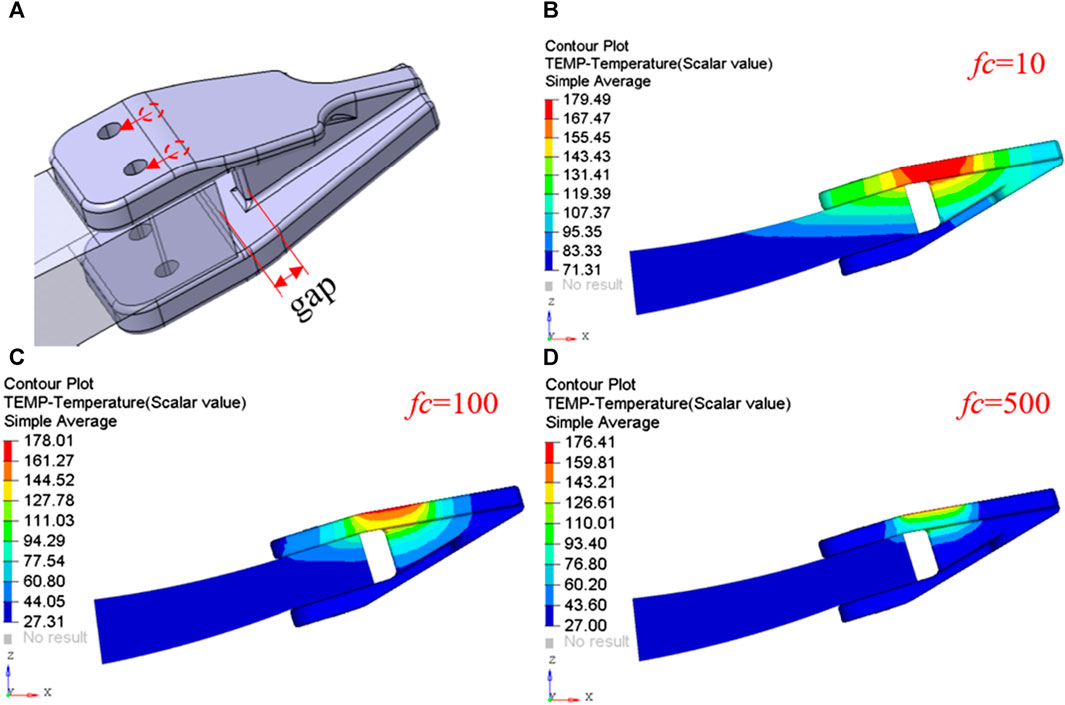
FIGURE 18. Joint scheme structure and thermal analysis results: (A) Joint structure and details; (B) Temperature distribution at the spring end when fc = 10
When the bolt-hole position is shifted towards the interior, it results in an increase in the stiffness of the spring end. The CLS layer must be appropriately adjusted to satisfy the stiffness criteria of the leaf spring. Proper adjustment of the composite ply is necessary to satisfy the stiffness criteria of the spring. Simultaneously, diminishing the spatial separation between the bolt hole and the spring end will result in an augmentation of the shear stress. To enhance the shear strength at the bolt hole, it is possible to apply multiple layers of carbon fiber at a 45-degree angle on both the top and bottom surfaces in the spring end.
The proposed construction will undergo the processes of manufacturing, assembly, and testing. During the bench test, it is necessary to monitor the temperature at the metal joint and bolt hole, as depicted in Figure 19A. Observe and record the fluctuations in temperature occurring at the terminal point of the spring during a duration of 600 min. The data collection intervals consist of measurements taken at 20-min intervals within the time range of 0–100 min, and at 40-min intervals within the time range of 100–600 min, the findings are shown in Figure 19B. The temperature at each point along the spring experiences a quick increase during the initial 0–100 min period. Subsequently, between 100 and 300 min, the temperature of the spring undergoes oscillations. Finally, after 400 min, the temperature reaches a level of stability. The metal joint has a maximum temperature of 140°C (RT2), whereas the composite bolt has a maximum temperature of 73°C (RT1). The temperature of RT1 is lower than the glass transition temperature (Tg) of the resin. The metal joint scheme exhibits a discernible heat dissipation effect in comparison to the original construction.
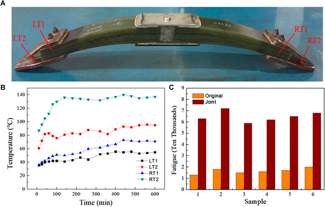
FIGURE 19. Metal joint spring and bench test results: (A) a Sample of CLS for joint solution; (B) LT1, LT2, RT1, RT2 points temperature curve; (C) Comparison of fatigue performance with different schemes.
Figure 19C shows the fatigue performance comparison between the joint and the original plan, the test method and device refer to Section 3.2. The CLS heat is decreased by using joints rather than the original plate. The spring’s life has also been extended, as evidenced by the figure depicting the original plan of the spring’s average fatigue life of 15,600 times for the six samples and 65,500 times for the joint. This means that the life of the spring is now 4.2 times longer than its original option, indicating a significant improvement in fatigue.
6.3 Road test
Conduct a loading test on the CLS joint scheme to ascertain its operational efficacy within the vehicle. The vehicle is equipped with a load of 33 tonnes of sand. To assess the thermal fatigue characteristics of the joint plan, a road test is employed to evaluate the resilience of this particular design. The road test is administered during the summer, as shown in Figure 20. The site is located at Dingyuan, Anhui Province, China, at coordinates 32°20′N and 117°60′E. During the summer season, the average daily temperature reaches 26°C. Following the completion of a 3000 km road strengthening exercise and a subsequent 2000 km performance road test, it has been seen that the CLS remains structurally sound without any discernible signs of damage. The findings indicate that the CLS utilized in this joint scheme demonstrates initial compliance with the service criteria.
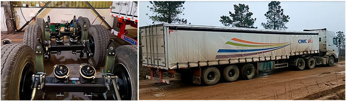
FIGURE 20. Joint scheme CLS assembly and road test.
7 Conclusion
This study investigated the failure mode of SCLS under mechanical thermal fatigue. Infrared and thermocouple measurements were employed to measure the temperature change of the composite spring end. At the same time, crack trend of the CLS was observed and the causes of the spring failure were discussed. Based on the analysis of the spring’s failure mode, two methods have been implemented to enhance the initial structure: the inclusion of an insulating panel and the utilization of a metal junction. The primary results are as follows.
(1) The fatigue life of leaf springs is strongly influenced by their temperature. When the temperature surpasses the glass transition temperature (Tg point) of the resin for a specific duration, fractures become visible in the vicinity of the bolt orifice of the composite spring. As the temperature of the spring rises, the fracture undergoes expansion and enlargement. Once the crack reaches a specific stage, the temperature of the composite body exhibits a tendency to stabilize. The significant crack had already expanded while the minor fracture continued to grow. The stiffness of the CLS continued to decrease. Once it reached thecritical limit, the spring had completely failed as a result of delamination fracture.
(2) Through experimental investigations, three distinct models of thermal fatigue failure in composite leaf springs were identified. These models include resin layer delamination failure, interface failure between the fiber and resin layer, and fiber pull-out failure. Based on the 2D model analysis, it was observed that the presence of defects in the laminated layer leads to a notable increase in stress in the S11 direction. Additionally, stress concentration is observed in the vicinity of these defects. The mentioned factor has the potential to lead to an accelerated damage of the CLS when subjected to thermal fatigue loading.
(3) The mitigation of thermal fatigue failure in SCLSs is facilitated by heat dissipation as opposed to heat insulation. The inclusion of an insulating panel at the end of the spring can effectively decelerate the rate at which heat is transferred to the spring, although it does not possess the capability to impede the overall increase in heat. Over an extended period, the spring will ultimately experience failure. The implementation of a metal joint scheme allows for the positioning of the composite body at a considerable distance from the spring’s friction area. The implementation of this technique has the potential to significantly enhance the thermal dissipation of the spring end and mitigate the thermal accumulation within the composite component.
(4) Through bench test comparison, the average thermal fatigue life of the CLS using the joint scheme is 65,500 cycles, which is 4.2 times that of the original scheme, and the improvement effect is significant. At the same time, the plan has undergone road testing under 5,000 km of extreme conditions. The experiment serves to validate the execution of this approach in very challenging operational environments.
The phenomenon of thermal fatigue failure in CLSs is a very complicated issue. This article analyzes the thermal-displacement coupling only approach to model the stress experienced by a defect under thermal load, without considering the growth of cracks. It is not certain that cracks will consistently develop at the particular position of the defect. Due to the current experimental and analytical conditions, the current research needs to be further improved in many aspects, and the complete failure mechanism needs further research.
Data availability statement
The original contributions presented in the study are included in the article/Supplementary material, further inquiries can be directed to the corresponding author.
Author contributions
LW: Methodology, Writing–original draft, Writing–review and editing. WC: Formal Analysis, Software, Writing–review and editing. XL: Investigation, Visualization, Writing–review and editing.
Funding
The author(s) declare that no financial support was received for the research, authorship, and/or publication of this article.
Conflict of interest
Author XL was employed by Ningbo Huaxiang Automotive Technology Co., Ltd.
The remaining authors declare that the research was conducted in the absence of any commercial or financial relationships that could be construed as a potential conflict of interest.
Publisher’s note
All claims expressed in this article are solely those of the authors and do not necessarily represent those of their affiliated organizations, or those of the publisher, the editors and the reviewers. Any product that may be evaluated in this article, or claim that may be made by its manufacturer, is not guaranteed or endorsed by the publisher.
References
Bai, T., Zhang, H., and Xu, H. (2011). Application of high temperature heat pipe in hypersonic vehicles thermal protection. J. Central South Univerisity Technol. 18 (4), 1278–1284. doi:10.1007/s11771-011-0833-0
Chen, H. S. (2001). The static and fatigue strength of bolted joints in composites with hygrothermal cycling. Compos. Struct. 52 (3-4), 295–306. doi:10.1016/s0263-8223(01)00022-8
Fabian, B., Christian, H., Francesco, I., and Girelli, A. (2019). Fatigue testing of GFRP materials for the application in automotive leaf springs. Procedia Struct. Integr. 19, 645–654. doi:10.1016/j.prostr.2019.12.070
Ferreira, J., Costa, J., and Reis, P. (1999b). Static and fatigue behaviour of glass-fibre-reinforced polypropylene composites. Theor. Appl. Fract. Mech. 31 (1), 67–74. doi:10.1016/s0167-8442(98)00068-8
Ferreira, J., Costa, J., Reis, P., and Richardson, M. (1999a). Analysis of fatigue and damage in glass-fibre-reinforced polypropylene composite materials. Compos. Sci. Technol. 59 (10), 1461–1467. doi:10.1016/s0266-3538(98)00185-7
Gort, N., Dbrich, O., Grieder, S., Küng, M., and Brauner, C. (2021). Experimental analysis of orthotropic strength properties of non-crimp fabric based composites for automotive leaf spring applications. Compos. Struct. 271 (3), 114154. doi:10.1016/j.compstruct.2021.114154
Hou, J. P., Cherruault, J. Y., Nairne, I., Jeronimidis, G., and Mayer, R. (2005). Evolution of the eye-end design of a composite leaf spring for heavy axle loads. Compos. Struct. 78 (3), 351–358. doi:10.1016/j.compstruct.2005.10.008
Jamadar, N. I., Kivade, S. B., and Raushan, R. (2018). Failure analysis of composite mono leaf spring using modal flexibility and curvature method. J. Fail. Analysis Prev. 18, 782–790. doi:10.1007/s11668-018-0418-4
Ke, J., Wu, Z. Y., Chen, X. Y., and Ying, Z. p. (2019). A review on material selection, design method and performance investigation of composite leaf springs. Compos. Struct. 226, 111277. doi:10.1016/j.compstruct.2019.111277
Kueh, J. T. J., and Faris, T. (2012). Finite element analysis on the static and fatigue characteristics of composite multi-leaf spring. J. Zhejiang Univ. Sci. A 13, 159–164. doi:10.1631/jzus.a1100212
Kumar, R., Sharma, S., Gulati, P., Singh, J. P., and Jha, K. (2023). Fabrication and characterizations of glass fiber-reinforced functional leaf spring composites with or without microcapsule-based dicyclopentadiene as self-healing agent for automobile industrial applications: comparative analysis. J. Mater. Res. Technol. 25, 2797–2814. doi:10.1016/j.jmrt.2023.06.039
Lo, K. H., Mccusker, J. J., and Gottenberg, W. G. (1987). Composite leaf spring for tank trailer suspensions. J. Reinf. Plastics Compos. 6 (1), 100–112. doi:10.1177/073168448700600108
Maa, R., and Cheng, J. (2002). A CDM-based failure model for predicting strength of notched composite laminates. Compos. Part B Eng. 33 (6), 479–489. doi:10.1016/s1359-8368(02)00030-6
Oh, S. H., and Choi, B. L. (2014). Prediction of spring rate and initial failure load due to material properties of composite leaf spring. Trans. Korean Soc. Mech. Eng. A 38 (12), 1345–1350. doi:10.3795/ksme-a.2014.38.12.1345
Pakdil, M., Sen, F., Sayman, O., and Benli, S. (2007). The effect of preload on failure response of glass-epoxy laminated composite bolted-joints with clearance. J. Reinf. Plastics Compos. 26 (12), 1239–1252. doi:10.1177/0731684407079769
Papacz, W., Tertel, E., Frankovský, P., and Kuryło, P. (2014). Analysis of the fatigue life of composite leaf springs. Appl. Mech. Mater. 611, 346–351. doi:10.4028/www.scientific.net/amm.611.346
Qian, C., Shi, W., Chen, Z., Yang, S., and Song, Q. (2017). Fatigue reliability design of composite leaf springs based on ply scheme optimization. Compos. Struct. 168, 40–46. doi:10.1016/j.compstruct.2017.02.035
Raghava, R. B., Ramachandra, R. V., and Mohana, R. K. (2015). Effect of fibre shape on transverse thermal conductivity of unidirectional composites. Sadhana 40, 503–513. doi:10.1007/s12046-014-0323-9
Rajesh, S., and Bhaskar, G. B. (2014). Response of composite leaf springs to low velocity impact loading. Appl. Mech. Mater. 591, 47–50. doi:10.4028/www.scientific.net/amm.591.47
Rajesh, S., Bhaskar, G. B., Venkatachalam, J., Pazhanivel, K., and Sagadevan, S. (2016). Performance of leaf springs made of composite material subjected to low frequency impact loading. J. Mech. Sci. Technol. 30 (9), 4291–4298. doi:10.1007/s12206-016-0842-x
Rao, G. S., Subramanyam, T., and Murthy, V. B. (2008). 3-D finite element models for the prediction of effective transverse thermal conductivity of unidirectional fiber reinforced composites. Int. J. Appl. Eng. Res. 3 (1), 99–109.
Sancaktar, E., and Gratton, M. (1999). Design, analysis, and optimization of composite leaf springs for light vehicle applications. Compos. Struct. 44 (2-3), 195–204. doi:10.1016/s0263-8223(98)00136-6
Shamsaei, N., and Rezaei, D. (2004). “Comparing fatigue life reliability of a composite leaf spring with a steel leaf spring,” in Proceedings of the ASME 7th biennial conference on engineering systems design and analysis (Manchester (GB): SAE International), 371–374.
Shankar, G., and Vijayarangan, S. (2006). Mono composite leaf spring for light vehicle design, end joint analysis and testing. Mater. Sci. 12 (3), 220–225.
Shokrieh, M. M., and Rezaei, D. (2003). Analysis and optimization of a composite leaf spring. Compos. Struct. 60 (3), 317–325. doi:10.1016/s0263-8223(02)00349-5
Soner, M., Tanoglu, M., Guven, N., Karaagac, M., and Akyali, R. (2012). Design and fatigue life comparison of steel and composite leaf spring. SAE Technical Paper 2012-01-0944.
Subramanian, C., and Senthilvelan, S. (2011). Short-term flexural creep behavior and model analysis of a glass-fiber-reinforced thermoplastic composite leaf spring. J. Appl. Polym. Sci. 120 (6), 3679–3686. doi:10.1002/app.33564
Tadesse, B. A., and Fatoba, O. (2022a). Theoretical and finite element analysis (FEA) of coated composite leaf spring for heavy-duty truck application. Mater. Today Proc. 62 (6), 4283–4290. doi:10.1016/j.matpr.2022.04.782
Tadesse, B. A., and Fatoba, O. (2022b). Design optimization and numerical analyses of composite leaf spring in a heavy-duty truck vehicle. Mater. Today Proc. 62 (6), 2814–2821. doi:10.1016/j.matpr.2022.02.367
Wang, L., Zhu, C., Lu, X., Zhang, Z., and Liang, S. (2023). Structural design and analysis of sliding composite mono leaf spring. SAE Int. J. Commer. Veh. 16 (3), 299–312. doi:10.4271/02-16-03-0020
Keywords: composite materials, sliding leaf spring, thermal fatigue, structural optimization, bench test
Citation: Wang L, Chen W and Lu X (2024) Thermal fatigue analysis and structural optimization of sliding composite leaf spring. Front. Mater. 11:1353274. doi: 10.3389/fmats.2024.1353274
Received: 10 December 2023; Accepted: 25 January 2024;
Published: 09 February 2024.
Edited by:
Antonio Caggiano, University of Genoa, ItalyReviewed by:
K. Viswanath Allamraju, Institute of Aeronautical Engineering (IARE), IndiaManoj Kumbhalkar, Jayawant Shikshan Prasarak Mandal (JSPM), India
Copyright © 2024 Wang, Chen and Lu. This is an open-access article distributed under the terms of the Creative Commons Attribution License (CC BY). The use, distribution or reproduction in other forums is permitted, provided the original author(s) and the copyright owner(s) are credited and that the original publication in this journal is cited, in accordance with accepted academic practice. No use, distribution or reproduction is permitted which does not comply with these terms.
*Correspondence: Lubin Wang, bill1988122@126.com