 Hairen Wang
 Jianyin Lei2
95% of researchers rate our articles as excellent or good
Learn more about the work of our research integrity team to safeguard the quality of each article we publish.
Find out more
ORIGINAL RESEARCH article
Front. Mater. , 19 January 2024
Sec. Polymeric and Composite Materials
Volume 11 - 2024 | https://doi.org/10.3389/fmats.2024.1341474
This article is part of the Research Topic Advancements in Composite Sandwich Materials: Fabrication, Characterization, Durability, Modeling and Applications View all 5 articles
Out-of-face gradient sandwich structures have been widely studied for their excellent impact resistance. One uniform and two out-of-plane gradient cores are proposed based on the bionic structure of Royal Water Lily, and the midspan deflection of the back panel and the energy absorption of the out-of-plane gradient sandwich structures under various blast loads are studied. Two frequently adopted methods of explosive loading are applied to the sandwich panels, and the responses are contrasted for the loads applied as a time-dependent pressure history versus imposition of the initial velocity. The effect of the fluid–structure interaction is considered in the blast impulsion, and the dynamic responses of the sandwich structures with different out-of-plane density arrangements are analyzed under two loading approaches. Results show that the energy absorption of the core layer under the prescribed velocity approach is approximately 3–5 times that of the applied pressure approach, while the back panel deflections of different out-of-plane gradient sandwiches are similar. There are significant differences in the deformation mechanisms of structures under these two types of impact loads. Under the same type of impact load, the core compression process of the out-of-plane positive gradient sandwich panel is decoupled from the whole tensile bending deformation process of the structure, whereas the core compression process of the out-of-plane negative gradient sandwich panel is strongly coupled with the whole tensile bending deformation process of the structure. The related research will lay the foundation for an in-depth understanding of the theoretical study of the impact of out-of-face gradient sandwich structures.
Sandwich structures generally comprise two parts: two thin but high-strength plates and a thick but low-density core. Sandwich structures can consider the characteristics of porous metal materials and overcome the shortcomings of low strength (Guo et al., 2024). Thus, they possess an improved structural performance. Sandwich structures are widely used in aerospace, automobile, and marine industries because of their excellent mechanical/structural performance (Lu and Yu, 2003; Wang et al., 2021; He et al., 2022; Liu et al., 2023; Zhang et al., 2023; Zhang et al., 2024). The concept of gradient core has been introduced for sandwich structure performance improvement. The gradient of the core can be achieved through three methods: variation in cell wall thickness (Zhang et al., 2016), changes in the size of cells (Wang et al., 2013; Zheng et al., 2016), and changes in the properties of core materials (Shen et al., 2013a; Shen et al., 2013b). The relative density gradients of the 2D cores have two orientations: parallel to the load and normal to the load. Many gradient studies focus on the first case, where the gradient and the loading directions are the same (Brothers and Dunand, 2008; Ajdari et al., 2009; Wang et al., 2009; Karagiozova and Alves, 2015; Liang et al., 2017; Yang et al., 2017).
However, in engineering, the slight gradient changes in the direction of relatively small dimensions in thin-walled structures may be caused by conscious (human involvement) or unconscious factors (differences in mechanical processing accuracy or material batches leading to performance differences). Therefore, the impact of small changes in the out-of-plane gradient of thin-walled structures on their impact resistance is a very interesting research direction. The wall thickness in the out-of-plane direction is relatively thin, thereby complicating the gradient design.
The dynamic mechanical response of the sandwich structure under blast loading has been widely studied. Two models can be used to study its dynamic deformation mechanism under blast loading. The first is the model based on yield locus, also named “three-stage” theory (Fleck and Deshpande, 2004; Qiu et al., 2005; Tilbrook et al., 2006; Liang et al., 2007; Zhu et al., 2010; Cui et al., 2012). The first stage of the theoretical model assumes that all the impulses act on the front panel. The momentum conservation is used to transform the impulses into the initial velocity field of the front panel. The second is the one-dimensional lumped parameter model (Deshpande and Fleck, 2005; Main and Gazonas, 2008; McMeeking et al., 2008; Ghoshal and Mitra, 2014). This model considers the dynamic equation of motion of the equivalent SDOF system to study the front panel, core compression, and back plate motion. The blast impulse transmission phase and the core compaction process are captured well. The difference between the two models lies in the loading modes: one is the prescribed approach, whereas the other is the applied pressure approach.
Ashkan (Vaziri and Hutchinson, 2007) investigated the responses of the square honeycomb and the folded plate core sandwich plates subjected to a time-dependent pressure history (applied pressure approach) and the imposition of initial velocity (prescribed velocity approach). A slight difference exists between the overall deflections of the back panel from the two approaches, and the greatest difference emerges in the degree of the core compression. The initial velocity approach can significantly overestimate the core crushing and energy dissipation. When the response time characterizing the overall panel motion is longer than the blast period, the loading is commonly represented as an initial impulse or velocity imparted to the panel, with the impulse derived from Fluid-Structure Interaction (FSI) theory. This approximation is compared with the more accurate approach of applying the time-varying pressure history derived from fluid interaction theory to the sandwich face-plate.
Plenty of numerical simulations have been designed by changing the relative density gradients of the core and the blast impulses to study the performances and deformation mechanisms of sandwich structures with different out-of-plane gradient cores of thin-walled sandwich structures under the two loading approaches. Inspired by Royal Water Lily (RWL)’s venation, we propose the bio-inspired honeycomb core of RWL. The out-of-plane compressive strength of RWL bionic honeycomb is superior to the out-of-plane compressive performance of several common honeycombs such as quadrilateral honeycomb, hexagonal honeycomb, and rhombic honeycomb (Wang et al., 2020a). The core relative density distribution is controlled by wall thickness variation. The sandwich cores are divided into three groups according to the relative density gradient, such as non-gradient core, out-of-plane negative gradient, and out-of-plane positive gradient cores. The impact of fluid–structure coupling is considered in the impulses. Two frequently adopted methods of explosive loading are applied to the sandwich plates. The responses are contrasted for the loads applied as a time-dependent pressure history versus the imposition of the initial velocity, and the dynamic responses of the sandwich structures with different out-of-plane density arrangements are analyzed under two loading approaches.
The outline of this paper is as follows. First, the core design strategy of RWL, core relative density, material parameters, and the blast loading considering the fluid–structure interaction (FSI) are analyzed in Section 2. The setup of the finite element model and the validation of the model are presented in Section 3. The numerical simulation is proved to be effective. The effectiveness of the finite element model is verified by comparing the finite element simulation solution and the exacting experiments under various blast loadings. Subsequently, the energy absorption, deflection of the back panel, and deformation mechanism of different out-of-plane gradient sandwich structures under two loading approaches are discussed in Section 4. Finally, the conclusions are presented in Section 5.
The distribution of RWL’s main and secondary veins is illustrated in Figure 1A. According to the natural distribution of leaf veins, the dimensionless size relationships in the simplified model are proposed as shown in Figure 1B. Sectional drawing of the sandwich model is shown in Figure 1C. The simplified model is similar to the one in our previous work (Wang et al., 2020b). In the plane, the model is divided into five parts according to the golden section ratio of the plant vein bifurcation. These parts are used to adjust the density gradient distribution of the core layer in the horizontal direction. In the vertical direction, the core layer structure is divided into three layers to adjust the density gradient.
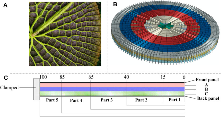
FIGURE 1. Core design strategy. (A) Natural structure of the RWL vein. (B) Finite element model of the core. (C) Sectional drawing of the sandwich model.
In general, the panel material of sandwich structures is harder than the core layer material. Therefore, the panels are made of 5,052 aluminum alloy (Qiang et al., 2014), and the core part is composed of 6060T4 aluminum alloy (Liu et al., 2015). A bilinear constitutive model, adopted for the constituent materials, is given by (Wang et al., 2021)
The specific material parameters are shown in Table 1. The strain rate sensitivities of the two adopted aluminum alloys are not considered in the analysis because they are relatively weak (Wang et al., 2020a).

TABLE 1. Specific material parameters of the sandwich structure.
The relative density of different parts of the core (as shown in Figure 1B) is calculated as follows in Eq. 2:
where Vm is the whole volume of the matrix and Vp is the apparent volume of the matrix.
In the present study, the core wall thickness is changed to adjust different relative density gradients. The core walls with different thicknesses are assembled to form the honeycomb core. The wall thickness of each cell in the honeycomb core is no longer uniform compared with that in nongradient cores. The specific parameters of the three core types, namely, uniform core (uniform gradient (UG), out-of-plane positive gradient core (Model-I), and out-of-plane negative gradient core (Model-II), are listed in Table 2.
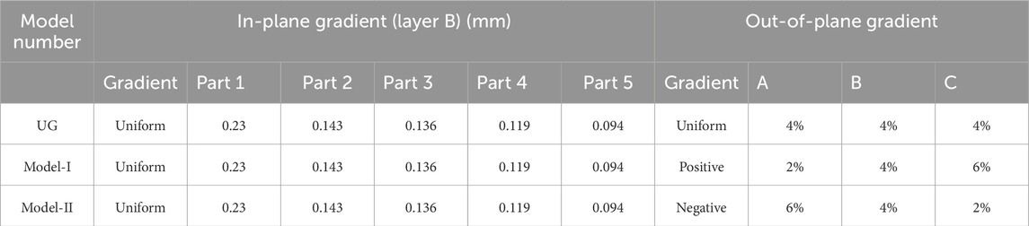
TABLE 2. Model type and related parameters.
The research on blast load has been carried out through experiments, theoretical analysis, and numerical calculation (Kambouchev and NoelsRadovitzky, 2006; Goel, 2015). The experimental method is relatively common. Henrych proposed an empirical formula for calculating the airborne blast load based on the experiment. One commonly used empirical formula of the overpressure peak of TNT in an infinite airfield proposed by Henrych (Henrych, 1979) is shown in Eq. 3,
where
The interaction of the incident shock waves in air with the sandwich structure is analyzed using the model proposed by Kambouchev et al. (KambouchevNoelsRadovitzky, 2006). In Ref. (Vaziri and Hutchinson, 2007), the theory is also called KNR theory. In the present study, the impulse/area I imparted to the front panel is calculated by KNR theory. The pressure is
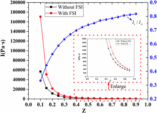
FIGURE 2. The unit area momentum curves transmitted to the sandwich panel with and without considering FSI (Z < 1).
As shown in Figure 2, when FSI is considered, the momentum/area, Ir, can be as much as 50% lower than
The shape of the core based on the simplification of the RWL leaf vein is shown in Figure 1B. The radius of the circular sandwich structure R is 100 mm. The thicknesses of the front panel (FP) and the back panel (BP) are 1 mm, and the core thickness is 15 mm. The edge of the circular sandwich panel is clamped. The core is divided into three layers vertically, each layer is 5 mm thick. The cores and face panels are meshed using S4R shell elements. These have a four-node, double-curved thin or thick shell, reduced integration, hourglass control and finite membrane strains. The mesh size is taken as 1 mm based on the grid convergence analysis. The adopted mesh of the FE model is shown in Figure 3.
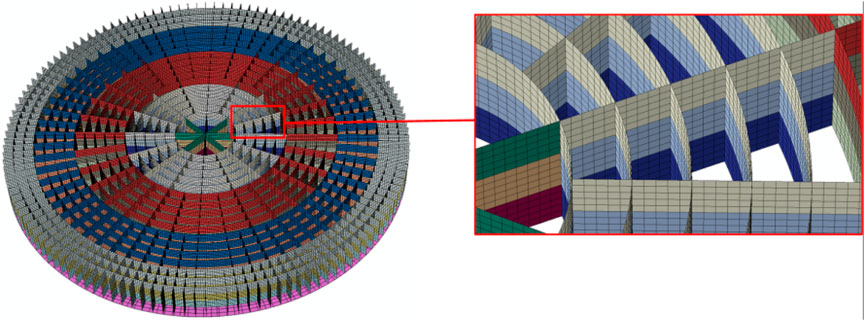
FIGURE 3. Adopted mesh of the FE model.
The core structure with different density gradients can be obtained by changing the shell element thickness. The three types of TNT masses were set to 15 g (Case 1), 25 g (Case 2), and 35 g (Case 3). The stand-off distance is 200 mm. Two loading approaches used by Ashkan are introduced in the present simulations. For the applied pressure approach, the pressure on the front face is Pr, and the load duration time is tR. For the prescribed velocity approach, the initial velocity of the front panel can be calculated by momentum conservation:
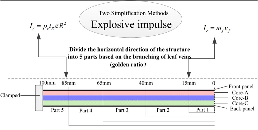
FIGURE 4. Two simplified loading methods.
The specific load settings are shown in Table 3.
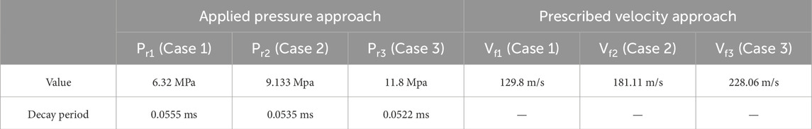
TABLE 3. Specific load settings of the two load approaches.
The responses of different gradient sandwich structures under the two loading approaches are detailed in Section 4.
In this section, the numerical approach is validated by a series of experiments (Nurick et al., 2009). Figure 5 presents the sandwich panel deformation. The numerical model deformation is in agreement with the final deformation mode of the experiment.
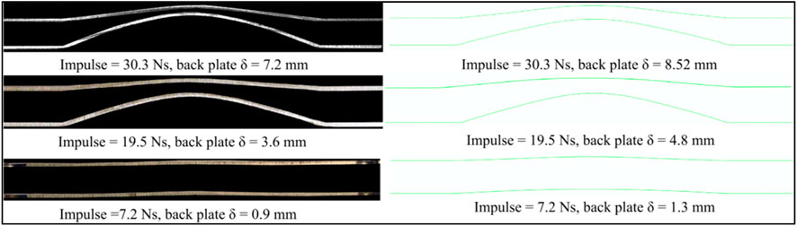
FIGURE 5. Final deformation diagram of the experiments and the simulations at various impulses.
The comparison of the midspan deflection of the back panel between the simulation and the experiment is also shown in Figure 6. The simulation results are very close to the experimental results, even though the results have a slight deviation. The analysis of the two fitting curves of the deflection–impulse curve shows that the error between the finite element simulation results and the experimental results is less than 20%, and it can be seen that the accuracy of finite element simulation is still acceptable within the impulse interval. Besides, from the fitting curve between finite element simulation and experimental results, it can be found that there is a difference of about 1 mm between the two results and it gradually reduces with the increase in the impulsive load strength. Therefore, the blast loading setting and material parameters of the numerical model are proved reliable for studying the blast resistance of the sandwich panels.
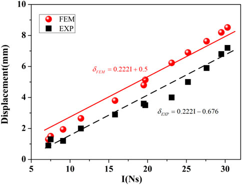
FIGURE 6. Comparison of finite element results with existing experiments.
The parametric analysis based on numerical analysis is conducted to discuss the responses of the gradient sandwich structures under the two loading approaches. The back panel deflection and the energy absorption are the two key performance parameters. The response of the uniform sandwich panels under the two loading methods is analyzed in Section 4.1. In Section 4.2, the energy dissipation of the sandwich panel with different density gradients under different loading approaches is mainly studied. The deflections of the back panel with different density gradients under different loading approaches are discussed in Section 4.3.
The response of a uniform core layer under different loading methods is first studied as a reference. The plastic dissipation is normalized by the initial kinetic energy (KE in the following figures) imparted to the plate under the prescribed velocity approach for the following sections to compare the core energy absorption capacity under different impulse conditions.
As shown in Figure 7, the energy absorptions of the uniform sandwich structures with various relative densities under two loading approaches are studied. The energy absorption of the uniform sandwich structures shows that the estimation of the sandwich panel’s energy absorption is quite different between the two loading methods.
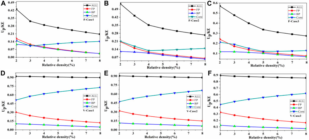
FIGURE 7. The energy absorption of uniform sandwich structures varies with the relative density cores under two loading approaches. (ALL represents dimensionless total energy absorption. FP, BP, Core represents dimensionless energy absorption of the front panel, the back panel and the core, respectively).
In the case of the applied pressure approach, the increase in the relative density of the core significantly reduces the structure’s total energy absorption. Moreover, the energy absorptions of the front and back panels are synchronously decreased. The core’s energy absorption is first decreased and then increased. The inflection point at which the energy absorption of the core layer first decreases and then increases varies as the load impulse increases. At an impulse of 15 g of explosives, the energy absorption efficiency of the core is the lowest at a relative density of 3%. However, this value is 4% and 5% at the impulse of 25 and 35 g explosives, respectively.
The relationship between compressive plateau stress and relative density can be expressed as (Fleck and Deshpande, 2004):
This finding indicates that in the case of the applied pressure approach, the extremely low point of the energy absorption efficiency of the core gradually increases as the load impulse increases. Moreover, the graph shows that the energy absorption of the upper and lower panels gradually decreases with the increase in the relative density of the core. The energy absorption efficiencies of the two panels are gradually approaching and follow the same pattern. This finding indicates that under this explosive load impulse, the deformation of the upper and lower panels at the center of the core layer tends to be consistent as the relative density of the core layer increases. Moreover, the compression at the center of the core layer decreases. However, the overall energy absorption efficiency of the core layer gradually increases. The comparison of the energy absorption efficiency of different parts of the structure under these three working conditions shows that the energy absorption efficiency of each sandwich panel part varies under the loading of the force–time curve.
In the case of the prescribed velocity approach, the total energy absorption of the structure changes slightly while the energy absorption of the core increases gradually with the increase in the core density. For the energy absorption of the upper and lower panels, the energy absorption efficiency of the front panel decreases significantly as the relative density increases, whereas that of the rear panel does not change significantly. The comparison of the energy efficiencies of each sandwich panel part under different explosion loads shows that the trend and numerical range of energy absorption rate in each part are approximately consistent under the three working conditions.
In terms of the total amount of energy absorption, the normalized energy absorption of the core under the prescribed velocity approach is approximately 2–3 times higher than that under the applied pressure approach. The normalized plastic dissipation energy decreases with the increase in the relative density of the core for both loading approaches. According to Figure 7, core crushing and energy dissipation can be significantly overestimated by the initial velocity approach.
For the simplified forms of explosive loads, such as rectangular pulse loads, the magnitude of pulse load P (MPa) can also be obtained by adjusting the load action time based on the conservation of impulse,
Figure 8 shows a comparison of the total energy absorption and core layer energy absorption of a 4% relative density sandwich panel under two loading conditions. Under the two loading conditions of 4%, the relative density sandwich panels, the total energy absorption efficiency of the sandwich panel, and the energy absorption efficiency of the core layer show a decreasing trend with the increase in force application time. As the loading time decreases, the total energy absorption efficiency and the core layer energy absorption efficiency gradually approach the speed loading method.
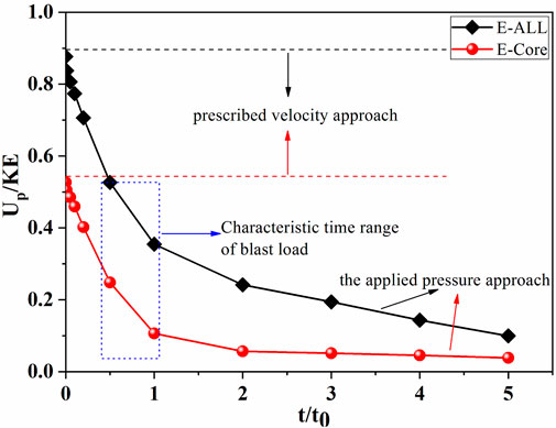
FIGURE 8. Comparison of the total energy absorption and the core energy absorption of the sandwich panel with 4% relative density under two loading conditions.
The time scale of the explosion load characteristics investigated in this study, t/t0∼0.5, shows that the overall energy absorption efficiency of the 4% relative density sandwich panel structure under the prescribed velocity approach is 1.64 times that of the applied pressure approach, whereas the core layer energy absorption efficiency of the prescribed velocity approach is 2.2 times that of applied pressure approach. This finding indicates that under the pre-acceleration field loading method, the compression of the core layer far exceeds that of the sandwich panel core layer under the force–time curve loading method.
In addition, as t/t0 is gradually reduced, the energy absorption in the sandwich layer and the overall structure gradually approaches the results of the pre-acceleration field condition. This is because when the input impulse is constant, decreasing t/t0 increases the instantaneous impact force, thus allowing the sandwich panel to complete the energy input in a shorter period of time, which behaves more similarly to the velocity impact of the front panel. As the application time increases, the magnitude of the impact force decreases significantly. Considering the resistance of the core compressive strength to core compression, the compression of the core layer gradually decreases and the structural deformation will gradually change to an overall tensile bending mode.
Figure 9 shows the comparison of the panel deflections after two equivalent loading methods under the explosion impulse of 15, 25, and 35 g explosives. For the uniform sandwich circular plates, the deflection of the rear panel correspondingly decreases with the increase in relative density under different impact loads. At low impulses, the deflection of the rear panel under the two loading methods is close to the upper limit of the theoretical solution. The panel deflection under the two loading methods gradually approaches the lower limit of the theoretical solution as the impact load increases. The upper and lower limits of the theoretical solution are obtained based on Fleck’s theory (Fleck and Deshpande, 2004).
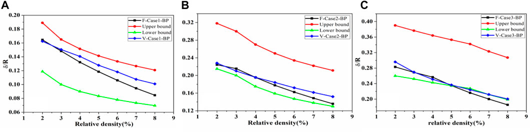
FIGURE 9. Deflection value of the back panel and the upper and lower limits of the theoretical solution for the uniform core layer under two equivalent loading modes with different cases. (The red line represents the upper limit of the theoretical solution. The green line represents the lower limit of the theoretical solution. The black line represents the deflection of the back panel under the applied pressure approach. The blue line represents the deflection of the back panel under the prescribed velocity approach).
Figure 9A shows that at this impact load level, the panel deflection after the uniform core layer under the two loading methods gradually increases with the increase in relative density, and the difference between the two gradually increases from 3% relative density. The deflection of the back panel should gradually decrease using the force–time curve method for loading compared with that using the prescribed velocity approach. The difference between the two is approximately 16.6% when the relative density is 8%.
Figure 9B shows that at the impact load level of 25 g explosive, the difference in the panel deflection after the uniform core layer under the two loading methods gradually increases after a relative density of 5%. The difference in back panel deflection between the two loading methods is relatively small when the relative density is less than 5%. However, the difference in the back panel deflection between the two loading methods gradually expands when the relative density exceeds 5%. At 8% relative density, the difference between the two is approximately 11%.
Figure 9C shows that at the impact load level of 35 g explosive, the difference in the panel deflection after the uniform core layer under the two loading methods gradually increases after a relative density of 6%. The difference in the back panel deflection between the two loading methods is relatively small when the relative density is less than 6%. However, the difference in back panel deflection between the two loading methods gradually expands when the relative density exceeds 6%. At 8% relative density, the difference between the two is approximately 9%.
In a uniform sandwich structure, the difference in the back panel deflection under the two loading methods is relatively low when the relative density of the core layer is low. As the relative density of the core layer increases, the difference in the back panel deflection under the two loading methods gradually appears. From the perspective of the explosion load’s impulse level, the anisotropy of the uniform core layer with a high relative density gradually decreases under two types of loading as the explosion impulse increases. The comparison of the panel deflection’s simulated values for the same relative density sandwich panel indicates that the simulated solution approaches the upper limit of the theoretical solution for low explosive loads under the two loading methods. Moreover, the simulated solution gradually approaches the lower limit of the theoretical solution as the explosive load increases.
As can be seen in Figures 7, 9, the difference in the overall energy absorption between the core and the sandwich panel under two different loading methods is greater than that in the deflection of the back panel. Similar to the research conclusion of Ashkan et al. (Vaziri and Hutchinson, 2007), the results in the present study indicate that for uniform sandwich panels, the difference in the back panel deflection of this bio-mimetic sandwich circular panel is relatively small under the two loading methods, whereas the overall compression of the core layer under the prescribed velocity approach far exceeds that under the applied pressure approach.
The difference in energy absorption for uniform sandwich structures under different loading conditions is mainly due to the different ways in which the impact loads act on the sandwich panels. This makes the deformation mechanism of the sandwich structure different. Through the applied pressure approach, the front panel of the sandwich panel receives the external pressure as well as the resistance of the core in a short period of time. For the front panel of the sandwich structure, before the external force and the core layer platform stress to reach equilibrium, this is an accelerated movement process from zero, the front panel impact on the core layer leads to core layer compression, and when the external force continues to reduce, the sandwich structure overall reaches a consistent motion process, the front panel gradually decelerates until it matches the overall speed of the structure. However, for the prescribed velocity approach, the front panel is always in decelerating motion, and under the action of the core layer resistance, the front panel decelerates from a very high velocity until it is in line with the overall velocity of the structure.
The two different deformation and motion mechanisms lead to a dramatic change in the core compression of the structure and a very different energy absorption in the structure. However, due to the certain impulse, although the deformation mode is different in the fluid-solid coupling stage and the core layer compression stage, the final deflection during the overall motion state of the structure stays approximately the same.
Given that the density gradient of the core layer can significantly impact the response of the structure, the response of the outer gradient core layer under two loading methods must be studied.
The energy absorption of the out-of-plane gradient core is shown in Figure 10. The initial impulses of the two loading methods are the same. The energy absorption of the core layer under the prescribed velocity approach is approximately 3–5 times that of the applied pressure approach. For the prescribed velocity approach, a slight difference exists in the energy absorption of the core layer with different gradients. This finding indicates that under this loading method, the small changes in the out-of-plane gradient slightly affect the total energy absorption of the core layer. However, the total energy absorption of different gradient core layers varies greatly under the applied pressure approach. This finding indicates that under this loading method, the density gradient is sensitive. Model-I has the best energy absorption capacity under the applied pressure approach.
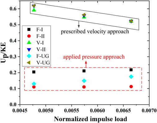
FIGURE 10. Energy absorption of the single gradient core.
Moreover, no obvious downward trend is observed with the increase in impulse load for the normalized plastic dissipation energy of the cores under the applied pressure approach. However, in the case of the prescribed velocity approach, the normalized plastic dissipation energy of the core decreases with the increase in impulse load strength. Therefore, the choice of load form affects the judgment of the energy absorption capacity of the structure when dealing with explosion impact problems.
A comparative analysis is conducted on the dimensionless energy absorption of the core layers in the out-of-plane direction under different loading cases to study further the energy absorption and distribution law of the core. The specific results are shown in Figure 11.
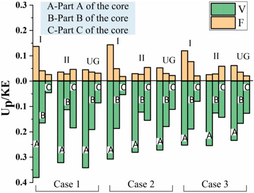
FIGURE 11. Dimensionless energy absorption of various core parts in different cases.
Figure 11 shows that the applied pressure approach is above the horizontal axis, and the prescribed velocity approach is below the horizontal axis. For the applied pressure approach, the energy absorptions of the A, B, and C layers in Model-I and the UG decrease gradually. In Model-II, the energy absorption of the C layer is relatively large. For the prescribed velocity approach, the A layer energy absorption of all core types is the highest.
The back panel deflections of the out-of-plane gradient sandwich panel under the two loading approaches are shown in Figure 12. No obvious differences exist in the back panel deflections of different out-of-plane gradient sandwich structures under different impulse levels.
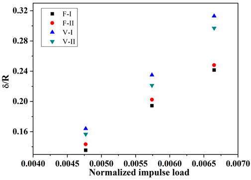
FIGURE 12. Influence of the out-of-plane gradient on the back panel deflection.
For the small gradient changes in the out-of-plane direction, no significant change is observed in the deflection of the structure’s panel. However, the energy absorption of the core layer has significant differences under different loading methods. Nevertheless, the back panel deflection is not significantly different. Further research is needed on this phenomenon.
To further investigate the deformation modes of the sandwich panels under blast loading, the velocity curves of the front and back panels are extracted. Fleck divides the response of the sandwich panel under impact into three response stages based on the difference in response time, namely, fluid solid coupling stage - stage I, core layer compression stage - stage II, and overall motion stage of the sandwich panel - stage III (Fleck and Deshpande, 2004; Qiu et al., 2005; Tilbrook et al., 2006; Liang et al., 2007; Zhu et al., 2010; Cui et al., 2012). The velocity–time curves of the midspan of the front and back panels under the two loading approaches are shown in Figures 13, 14. Figure 13A shows that for the applied pressure approach and the out-of-plane negative gradient sandwich panel (denoted as F-I), the velocity of the front panel increases more quickly than that of the back panel. When the velocity of the front panel reaches its maximum value, it begins to decelerate and reaches the same velocity as that of the back panel at teq= 0.21 ms. The front panel will move at a higher speed than the back panel before reaching the same speed, causing the core to compress. However, after a common speed is reached (Phase I of Stage III), the velocity of the back panel exceeds that of the front panel. This finding indicates that the core is not being compressed but reversed and stretched. Afterward, the velocity of the back panel begins to decline at tbd = 0.33 ms (Phase II of Stage III). Phase II of Stage III ends at t = 0.4 ms. Teq < tbd indicates that Stage II and Stage III are decoupled at this time.
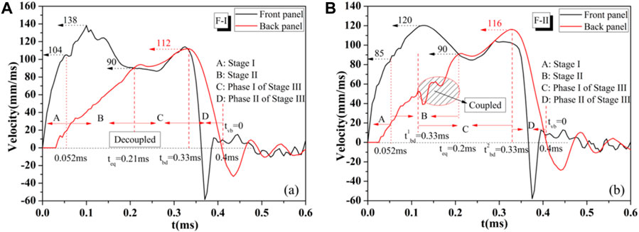
FIGURE 13. Velocity–time curves of the midspan of the front and back panels under the applied pressure approach at pr3 (
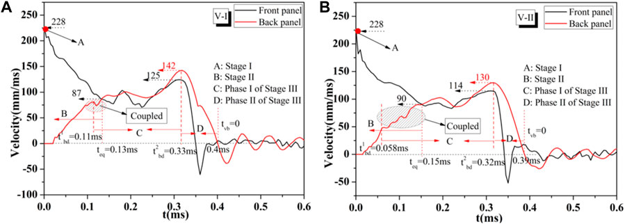
FIGURE 14. Velocity–time curves of the midspan of the front and back panels under the prescribed velocity approach at pr3 (
For the applied pressure approach and the out-of-plane positive gradient sandwich panel (denoted as F-II), in the beginning, the velocity of the front panel increases equally with that of the back panel, as shown in Figure 13B. The speeds of the front and back panels begin to decrease at 0.12 ms and reach a common speed at 0.2 ms. Before the common speed is reached, the back panel speed experiences downward and upward fluctuations. Finally, a common velocity is reached at teq at t = 0.2 ms. This finding indicates that Stage II and Stage III are coupled in this situation. Stage III ends at 0.4 ms. The deformation mechanism of the two kinds of sandwich plates is different.
The velocity–time curves of the midspan of the front and back panels under the prescribed velocity approach are shown in Figures 14A, B. Under the velocity loading condition, the two sandwich panel types show the Stage 2 and Stage 3 coupling. However, the coupling degree of type I sandwich panel is far less than that of type II sandwich panel. Figure 14A shows that the back panel experiences slight downward and upward fluctuations in speed before it reaches the same velocity as the front panel. The cause of these fluctuations is the same as that of a series of fluctuations in Figure 14B, which originate from the out-of-plane density gradient. Therefore, the mode of coupling action appears in type I sandwich panel; however, it can be understood as the mode of global decoupling and local coupling. Figure 14B shows the velocity–time curve of the midspan of Model II under the prescribed velocity approach. The velocity of the back panel decreases at 0.058 ms before the front panel and the back panel reach a common velocity at 0.15 ms. This finding indicates that Stage II and Stage III are coupled in this case. The comparison of Figure 14A with Figure 14B shows that the slope of the velocity–time curve in Figure 14A is more moderate than that in Figure 14B in the beginning. This finding means that the resistance received by the front panel at the initial stage of core compressing is different. Moreover, the resistance given by Model I is small, whereas that given by Model II is large. However, the speed of the front panel of Model II decreases gradually compared with that of Model I during the compression process, as shown in Figure 14A.
The velocity–time curves of the midspan of the front and back panels under two loading approaches are studied. Two kinds of gradient sandwich panels are coupled with each other in Stage II and Stage III. Moreover, Stage II and Stage III of Model II under two loading approaches are coupled. Their deformation mechanisms are quite different. The common velocity is calculated as 88.17 mm/ms by calculating the momentum theorem, and the error of finite element results is approximately 2%.
The study is an investigation of two methods of load application to the sandwich panel. The responses are compared for load application as a time dependent pressure history versus the imposition of the initial velocity. Core crushing shows the greatest difference. Core crushing and energy dissipation can be significantly overestimated using the initial velocity approach. The energy dissipation and the deflections of the cores with different gradients are very different when the density gradient is introduced. Based on the results among the present sandwich panels, the following conclusions can be drawn:
(1) Under the two loading conditions, the deflections of the two kinds of sandwich structures are quite different. For the applied pressure approach, Stage II and Stage III of the Model-I deformation process are decoupled from the whole tensile bending deformation process of the structure, whereas Stage II and Stage II of the Model-II deformation process are strongly coupled with the whole tensile bending deformation process of the structure. The two core deformation processes are all coupled for the prescribed velocity approach.
(2) In terms of energy absorption, the energy absorption of the core under the prescribed velocity loading approach is much higher than that under the applied pressure loading approach. Moreover, the plastic dissipation energy under the prescribed velocity loading approach is approximately 3–5 times that under the applied pressure loading approach at the same case of the impulse level. The whole plastic dissipation energy decreases with the increase in the relative density of the core.
(3) For the small gradient changes in the out-of-plane direction, no significant change is observed in the deflection of the sandwich structure’s panel. However, the energy absorption of the core layer has significant differences under different loading methods. Nevertheless, the back panel deflection is not significantly different. Further research is needed on this phenomenon. This finding may suggest that a direct positive relationship may not exist between the energy absorption of the core and the deflection of the structural panel, or a competitive relationship may exist between the energy absorption of the core and the structural deformation resistance. For example, there may be a critical state of “symbiosis” between energy absorption and deformation resistance in gradient structures. Beyond the critical threshold, there will be some “competition” between energy absorption and resistance to deformation. “The better the energy absorption of the core layer is, the stronger the structural deformation resistance is” may be existing only between some critical states. Therefore, for the core design of sandwich structures, the energy absorption of the core should be appropriately coordinated with the structural stiffness.
The original contributions presented in the study are included in the article/Supplementary material, further inquiries can be directed to the corresponding author.
HW: Writing–original draft. JL: Software, Writing–original draft. JC: Resources, Writing–review and editing. YL: Investigation, Writing–review and editing. JP: Methodology, Writing–review and editing. XM: Supervision, Writing–review and editing.
The author(s) declare financial support was received for the research, authorship, and/or publication of this article. This work is supported by the National Natural Science Foundation of China (grant numbers 52268047, 51868075, 12302490, and 11902215), Yulin High-tech Zone Science and Technology Bureau (grant numbers CXY-2021-27 and YGXKG-2023-106), Yulin City Key Laboratory for BIM Technology Application and Intelligent Construction of Prefabricated Buildings with a Grant No. of CXY-2021-146, the Shaanxi Provincial Department of Education Special Research Program Project with a Grant No. of 22JK0644, Yulin University High level Talent Research Launch Fund with a Grant No. of 22GK10. The financial contributions are gratefully acknowledged.
Author JC was employed by Yulin Construction Engineering Group Co., Ltd.
The remaining authors declare that the research was conducted in the absence of any commercial or financial relationships that could be construed as a potential conflict of interest.
All claims expressed in this article are solely those of the authors and do not necessarily represent those of their affiliated organizations, or those of the publisher, the editors and the reviewers. Any product that may be evaluated in this article, or claim that may be made by its manufacturer, is not guaranteed or endorsed by the publisher.
Ajdari, A., Canavan, P., Nayeb-Hashemi, H., and Warner, G. (2009). Mechanical properties of functionally graded 2-D cellular structures: a finite element simulation. Mater Sci. Eng-A 499, 434–439. doi:10.1016/j.msea.2008.08.040
Brothers, A. H., and Dunand, D. C. (2008). Mechanical properties of a density-graded replicated aluminum foam. Mater Sci. Eng-A 489, 439–443. doi:10.1016/j.msea.2007.11.076
Cui, X. D., Zhao, L. M., Wang, Z. H., Han, Z., and Fang, D. N. (2012). A lattice deformation based model of metallic lattice sandwich plates subjected to impulsive loading. Int. J. Solids Struct. 49, 2854–2862. doi:10.1016/j.ijsolstr.2012.04.025
Deshpande, V. S., and Fleck, N. A. (2005). One-dimensional response of sandwich plates to underwater shock loading. J. Mech. Phys. Solids 53 (11), 2347–2383. doi:10.1016/j.jmps.2005.06.006
Fleck, N. A., and Deshpande, V. S. (2004). The resistance of clamped sandwich beams to shock loading. J. Appl. Mech. 71 (3), 386–401. doi:10.1115/1.1629109
Ghoshal, R., and Mitra, N. (2014). On core compressibility of sandwich composite panels subjected to intense underwater shock loads. J. Appl. Phys. 115 (2), 024905. doi:10.1063/1.4861885
Goel, M. D. (2015). Blast: characteristics, loading and computation—an overview advances in structural engineering. India: Springer India.
Guo, H., Yuan, H., Zhang, J., and Ruan, D. (2024). Review of sandwich structures under impact loadings: experimental, numerical and theoretical analysis. Thin-Walled Struct. 196, 111541. doi:10.1016/j.tws.2023.111541
He, X., Huang, Z., Chen, Z., and Li, Y. (2022). Dynamic response of CFRP-lattice sandwich structures subjected to underwater shock wave loading. Thin-Walled Struct. 181, 109537. doi:10.1016/j.tws.2022.109537
Henrych, J. (1979). The dynamics of explosion and its use. New York: Elsevier Scientific Publishing Company.
Kambouchev, N., and NoelsRadovitzky, L. R. (2006). Nonlinear compressibility effects in fluid-structure interaction and their implications on the air-blast loading of structures. J. Appl. Phys. 100 (6), 063519. doi:10.1063/1.2349483
KambouchevNoelsRadovitzky, N. L. R. (2006). Nonlinear compressibility effects in fluid-structure interaction and their implications on the air-blast loading of structures. J. Appl. Phys. 100 (6), 063519. doi:10.1063/1.2349483
Karagiozova, D., and Alves, M. (2015). Propagation of compaction waves in cellular materials with continuously varying density. Int. J. Solids Struct. 71, 323–337. doi:10.1016/j.ijsolstr.2015.07.005
Liang, M., Li, Z., Lu, F., and Li, X. (2017). Theoretical and numerical investigation of blast responses of continuous-density graded cellular materials. Compos. Struct. 164, 170–179. doi:10.1016/j.compstruct.2016.12.065
Liang, Y. M., Spuskanyuk, A. V., Flores, S. E., Hayhurst, D. R., Hutchinson, J. W., McMeeking, R. M., et al. (2007). The response of metallic sandwich panels to water blast. J. Appl. Mech. 74 (1), 81–99. doi:10.1115/1.2178837
Liu, S., Huang, Z., and Li, Y. (2023). Insight into the underwater implosion mechanisms of thin-walled metallic cylindrical shells. Ocean. Eng. 276, 114129. doi:10.1016/j.oceaneng.2023.114129
Liu, Z., Hao, W., Xie, J., Lu, J., Huang, R., and Wang, Z. (2015). Axial-impact buckling modes and energy absorption properties of thin-walled corrugated tubes with sinusoidal patterns. Thin-Walled Struct. 94, 410–423. doi:10.1016/j.tws.2015.05.002
Lu, G. X., and Yu, T. X. (2003). Energy absorption of structures and materials. Cambridge: Woodhead Publishing.
Main, J. A., and Gazonas, G. A. (2008). Uniaxial crushing of sandwich plates under air blast: influence of mass distribution. Int. J. Solids Struct. 45 (7-8), 2297–2321. doi:10.1016/j.ijsolstr.2007.11.019
McMeeking, R. M., Spuskanyuk, A. V., He, M. Y., Deshpande, V., Fleck, N., and Evans, A. (2008). An analytic model for the response to water blast of unsupported metallic sandwich panels. Int. J. Solids Struct. 45 (2), 478–496. doi:10.1016/j.ijsolstr.2007.08.003
Nurick, G., Langdon, G. S., Chi, Y., and Jacob, N. (2009). Behaviour of sandwich panels subjected to intense air blast – Part 1: experiments. Compos. Struct. 91 (4), 433–441. doi:10.1016/j.compstruct.2009.04.009
Qiang, B., Liu, Y. J., and Kan, Q. H. (2014). Numerical simulation for three-point bending failure of aluminum foam sandwich panels with cohesive interface. J. Mater. Eng. 4, 97–101. doi:10.11868/j.issn.1001-4381.2014.11.017
Qiu, X. M., Deshpande, V. S., and Fleck, N. A. 2005, Impulsive loading of clamped monolithic and sandwich beams over a central patch. J. Mech. Phys. Solids, 53(5):1015–1046. doi:10.1016/j.jmps.2004.12.004
Shen, C. J., Lu, G., and Yu, T. X. (2013b). Dynamic behavior of graded honeycombs – a finite element study. Compos Struct. 98, 282–293. doi:10.1016/j.compstruct.2012.11.002
Shen, C. J., Yu, T. X., and Lu, G. (2013a). Double shock mode in graded cellular rod under impact. Int J Solids Struct. 50, 217–233. doi:10.1016/j.ijsolstr.2012.09.021
Tilbrook, M. T., Deshpande, V. S., and Fleck, N. A. 2006, The impulsive response of sandwich beams: analytical and numerical investigation of regimes of behaviour. J. Mech. Phys. Solids, 54(11):2242–2280. doi:10.1016/j.jmps.2006.07.001
Vaziri, A., and Hutchinson, J. W. (2007). Metal sandwich plates subject to intense air shocks. Int. J. Solids Struct. 44, 2021–2035. doi:10.1016/j.ijsolstr.2006.08.038
Wang, E., Gardner, N., and Shukla, A. (2009). The blast resistance of sandwich composites with stepwise graded cores. Int. J. Solids Struct. 46, 3492–3502. doi:10.1016/j.ijsolstr.2009.06.004
Wang, H., Li, S., Liu, Z., et al. (2020a). Out-of-plane compression performance of gradient honeycomb inspired by royal water lily. Chin. J. High Press. Phys. 34 (6), 82–90. doi:10.11858/gywlxb.20200562
Wang, H., Li, S., Liu, Z., et al. (2021). Mechanical behaviors of bi-directional gradient bio-inspired circular sandwich plates under blast loading. Explos. Shock Waves 41 (4), 043201. doi:10.11883/bzycj-2020-0132
Wang, X., Zheng, Z., and Yu, J. (2013). Crashworthiness design of density-graded cellular metals. Theor. Appl. Mech. Lett. 3, 031001. doi:10.1063/2.1303101
Wang, H., Li, S., Liu, Z., Wang, Z., and Li, Z. (2020b). Investigation on the dynamic response of circular sandwich panels with the bio-inspired gradient core. Thin-Walled Struct. 149, 106667. doi:10.1016/j.tws.2020.106667
Yang, J., Wang, S., Ding, Y., Zheng, Z., and Yu, J. (2017). Crashworthiness of graded cellular materials: a design strategy based on a nonlinear plastic shock model. Mater Sci. Eng-A 680, 411–420. doi:10.1016/j.msea.2016.11.010
Zhang, J., Huang, Z., Chen, Z., and Li, Y. (2023). Dynamic response of spherical shells subjected to the underwater impulse. Ocean. Eng. 286, 115568. doi:10.1016/j.oceaneng.2023.115568
Zhang, J., Wang, Z., and Zhao, L. (2016). Dynamic response of functionally graded cellular materials based on the Voronoi model. Compos Part B-Eng 85, 176–187. doi:10.1016/j.compositesb.2015.09.045
Zhang, W., Wang, H., Lou, Xi, Yan, Z., Shao, J., Wu, T., et al. (2024). On in-plane crushing behavior of a combined re-entrant double-arrow honeycomb. Thin-Walled Struct. 194, 111303. doi:10.1016/j.tws.2023.111303
Zheng, J., Qin, Q., and Wang, T. J. (2016). Impact plastic crushing and design of density-graded cellular materials. Mech. Mater 94, 66–78. doi:10.1016/j.mechmat.2015.11.014
Keywords: gradient sandwich, midspan deflection, energy absorption, blast loading, fluid-structure interaction
Citation: Wang H, Lei J, Chen J, Li Y, Peng J and Ma X (2024) Comparative study on the dynamic response of an out-of-plane gradient bionic sandwich circular plate under two types of impact loading. Front. Mater. 11:1341474. doi: 10.3389/fmats.2024.1341474
Received: 20 November 2023; Accepted: 08 January 2024;
Published: 19 January 2024.
Edited by:
Senthil Muthu Kumar Thiagamani, Kalasalingam University, IndiaReviewed by:
Ying Li, Beijing Institute of Technology, ChinaCopyright © 2024 Wang, Lei, Chen, Li, Peng and Ma. This is an open-access article distributed under the terms of the Creative Commons Attribution License (CC BY). The use, distribution or reproduction in other forums is permitted, provided the original author(s) and the copyright owner(s) are credited and that the original publication in this journal is cited, in accordance with accepted academic practice. No use, distribution or reproduction is permitted which does not comply with these terms.
*Correspondence: Hairen Wang, NjczNTA1NTIxQHFxLmNvbQ==; Yugen Li, MTU4NTg3MDg2QHFxLmNvbQ==
Disclaimer: All claims expressed in this article are solely those of the authors and do not necessarily represent those of their affiliated organizations, or those of the publisher, the editors and the reviewers. Any product that may be evaluated in this article or claim that may be made by its manufacturer is not guaranteed or endorsed by the publisher.
Research integrity at Frontiers
Learn more about the work of our research integrity team to safeguard the quality of each article we publish.