
95% of researchers rate our articles as excellent or good
Learn more about the work of our research integrity team to safeguard the quality of each article we publish.
Find out more
ORIGINAL RESEARCH article
Front. Mater. , 26 January 2024
Sec. Mechanics of Materials
Volume 11 - 2024 | https://doi.org/10.3389/fmats.2024.1329549
The excessive destruction of surrounding rock in deep tunnel will change the original environmental state and destroy the natural ecological balance. Research on the dynamic response characteristics and damage thresholds of rock masses in deep environments plays a crucial role in determining the excavation range of blasted rock and establishing safety construction scheme. This study employs numerical simulation techniques to investigate the dynamic response characteristics of surrounding rock under different ground stress conditions. By introducing the dynamic ultimate tensile strength criterion, critical fracture stress threshold, and maximum damage radius of rock under coupled dynamic-static loading conditions are determined. The research shows that under uniaxial ground stress condition, increasing ground stress inhibits damage to the surrounding rock and the extension of cracks in the excavation area, while imposing restrictions on the attenuation rate of explosive stress. Under bidirectional equal ground stress condition, an increase in lateral pressure coefficient inhibits the development of damage zones along the excavation contour, yet enhances the extension of cracks in the maximum principal stress direction. Moreover, when lateral pressure coefficient becomes excessively large, the attenuation rate of explosive stress significantly increases. Based on the threshold values of peak particle velocity (PPV), the functional relationship is established to predict safety criteria for deep blasting excavation.
Blasting technology in traffic, mining, tunnel and other large engineering construction plays an indispensable role (Hong et al., 2023; Pan et al., 2023; Wu et al., 2023). In recent years, with the rapid development of economic construction, the construction of civil engineering and hydraulic engineering has gradually deepened, and the complex stress conditions make the tunnel blasting excavation face increasingly strict challenges (Mahmoodzadeh et al., 2022; Chai et al., 2023). In the process of blasting excavation of underground engineering, explosion load and stress redistribution of surrounding rock are the main causes of damage of surrounding rock of deep tunnel (Fan et al., 2015). The change of rock mass occurrence environment and rock mass deformation caused by excavation further lead to the deterioration of rock mass performance, which is not conducive to the stability of surrounding rock, deformation control and construction safety (Xu et al., 2023; Zheng et al., 2024). In addition, excessive damage to surrounding rock of deep tunnel will change the original environmental state, destroy the groundwater circulation system, and even cause the depletion of surface water sources, the decline of water quality, and the decrease of soil water content, thus affecting the normal growth of plants and destroying the natural ecological balance. Therefore, to reveal the damage mechanism of surrounding rock induced by blasting, it is necessary to deeply explore the blasting damage effect and disturbance response characteristics of surrounding rock under complex stress conditions.
The vibration and damage evolution of rock mass caused by blasting is one of the key problems in blasting engineering and rock mechanics (Guan et al., 2020; Huo et al., 2020; Liu et al., 2022). Relevant scholars have carried out some research by means of theoretical deduction, numerical simulation and engineering test (Uysal et al., 2007; Sazid and Singh, 2013; Li et al., 2016; Yang et al., 2016). Xie et al. (2017) studied the excavation of cut blasting tunnel by using numerical simulation method, and studied the damage mechanism of cut blasting under different hydrostatic pressure and lateral pressure coefficient by using Riedel-Hiermaier-Thoma (RHT) model, which provided solutions to the problems of actual cut blasting. Yi et al. (2017) used LS-DYNA to study blasting breakage in sublevel caving mining, and discussed the effects of delay time and detonator location on fragmentation. Wang et al. (2021) studied the effect of repeated explosive loading on rock damage accumulation. They found that even repeated blasting did not contribute much to rock cracking in the direction of minor principal stress. Yilmaz and Unlu. (2013) discussed the effects of loading rate and anisotropic high ground stress on the blasting damage area, and verified the influence of the magnitude and direction of principal stress on the development of cracks around the borehole. Hajibagherpour et al. (2020) simulated the rock breaking mechanism of single-hole blasting shock wave, analyzed the stress around the blasthole, the number of explosion-induced cracks and the fracture density, and compared with the corresponding experimental results. Simha et al. (1983) conducted a series of experiments with Plexiglass discs to study the influence of static stress field on blasting rupture mode. The results show that the optimal fracturing direction is the direction of maximum principal stress. Zhu et al. (2013) conducted a numerical simulation of the rock failure process under static and dynamic combined loads, and the research showed that before the action of blasting loads, the lateral pressure coefficient controlled the stress distribution around the blasthole, and the damage area around the blasthole was closely related to the ground stress, and the ground stress distribution also had an impact on the direction of crack growth.
To sum up, scholars have carried out solid work in the aspects of deep tunnel blasting excavation and dynamic damage mechanism, but the analysis on the damage mechanism of surrounding rock induced by tunnel blasting excavation under different ground stress conditions is still insufficient, and most of them are limited to the simulation of single hole or double hole blasting (Cheng et al., 2021; Cheng et al., 2022). In particular, there are few reports on the research on the blasting excavation effect of the full section of the tunnel. It is difficult to obtain the critical index of deep rock mass, and it is biased to analyze the mechanical characteristics of deep blasting rock mass by simple qualitative analysis and empirical formula. Field test methods considering the damage characteristics of surrounding rock are costly and difficult, and there are great differences between various test methods (Ji et al., 2021a; Ji et al., 2021b). Therefore, the method combining theoretical analysis and numerical simulation is adopted to carry out the dynamic response characteristics of surrounding rock caused by blasting excavation of tunnel under different ground stress levels. The maximum damage radius of rock mass is determined by introducing dynamic limit tensile strength criterion, and the general function expression of rock damage PPV threshold in deep rock mass blasting excavation is established.
During the process of blasting excavation in deep-seated rock mass, the stress experienced by the surrounding rock is the result of the coupling of dynamic explosive loads and static ground stresses. Without considering stress concentration, the circular tunnel model is approximated as a thick-walled cylinder, and the stress process of the rock mass is shown in Figure 1.
Affected by the far site stress, the plane strain calculation model for the ground stress on the excavation surface corresponding to each blasting section is as follows (Lu et al., 2012):
Where σri, σrϕi, and τrϕi are the radial normal stress, tangential normal stress, and shear stress on the excavation face of the ith blasting section, respectively. η is the lateral pressure coefficient, η = σV/σH.
Without the initial stress in rock mass, the dynamic stress field induced by blasting load can be attributed to the problem of column cavity excitation. The governing equation in cylindrical coordinate system is:
Where u is the displacement induced by the explosive load on the blasthole; r is the distance from the center of the blasthole; σrb and σθb are the radial and tangential stresses induced around the blasthole due to the explosive load; λ and μ are the Lamé constants; CP is the speed of elastic waves in the rock, and ρ is the density of the rock.
Millisecond delayed excavation of the whole section of the tunnel, blasting stress waves propagate from the excavation to the deep surrounding rock, and the stress field in the surrounding rock is superimposed by the static stress field and the dynamic stress field stimulated by the explosion load. The stress state at any point in the surrounding rock can be described as follow:
Where σr (r,t) and σϕ(r,t) are the radial and tangential dynamic stresses in the surrounding rock, respectively. σrs(r) and σϕs(r) are the pre-blasting static radial and tangential stresses in the surrounding rock, calculated by Eq. 1. σrb (r,t) and σθb (r,t) are the radial and tangential dynamic stresses induced by the explosive load in the surrounding rock during the blasting process, computed by Eq. 3.
Rock is considered a brittle material with markedly lower tensile strength compared to its compressive strength. Under the influence of explosive load, the rock assume a triaxial stress state characterized by a combination of tension and compression. The crushing zone is the result of compressive stress, while the fracture zone is a consequence of tensile failure. According to the Mises criterion, when rock failure occurs the stress at any point in the rock σi fulfills the following criterion:
The tensile crack caused by toroidal dynamic tensile stress is dominant in blasting load. Therefore, the criterion for damage of the surrounding rock is based on the maximum tensile stress, as formulated in Eq. 5 (Lv et al., 2021):
When the explosion stress wave decays in the rock medium just enough that the rock no longer suffers tensile failure, it can be considered that the rock is in a critical damaged state. In this critical damaged state, explosion stress wave is given by:
Where σci and σti are the dynamic compressive strength and dynamic tensile strength of the rock on the critical damaged surface; b is the lateral stress coefficient, b = v/(1-v), v is the Poisson’s ratio.
In the fracture zone of rock, the strain rate further decreases, and the dynamic tensile strength of rock varies little with strain rate. In this case, within the range of strain rates encountered in rock engineering blasting, assume:
Therefore, Eq. 6 can be reformulated as:
There are differences in the explosive stress σci in rocks under different ground stresses. The σci and other dynamic response parameters located at the maximum damage boundary can be selected as the criterion of the damage threshold. The damage threshold Dcr can be expressed as:
Where Dσci, DVci, and DUci are the stress, blast vibration velocity, and particle displacement thresholds at the critical damage in the rock, respectively.
The calculation model has a net width of 12.0 m, net height of 6.0 m, resulting in a net cross-sectional area of 56.52 m3. The borehole diameter is 40 mm, utilizing radial coupling charges. The designed cut depth is 2.5 m, with a charge segment length of 2.0 m. The rock type is sandstone, which is relatively hard. Smooth blasting is employed, and the blastholes arrangement is as shown in Figure 2. The blasting parameters are listed in Table 1.
The three-dimensional finite element model is depicted in Figure 3. The six outer surfaces of the model were set as non-reflective boundaries, and constraints were applied in the thickness direction. The surrounding rock was modeled using the conventional Lagrange algorithm, while the explosive and air materials were modeled using the Arbitrary Lagrangian-Euler (ALE). The total number of elements in the rock and coupling medium in the computational model is approximately 900,000. The size and mesh division of the model were kept consistent for different conditions.
The rock is described using the HJC model, with parameters as shown in Table 2. In this study, explosive with a density of 1,250 kg/m³ and a detonation velocity of 3,200 m/s. The JWL equation is employed to depict the relationship between pressure and volume during the explosion process, with parameters detailed in Table 3.
Simulation of tunneling and blasting under different confining pressures was carried out, and specific working conditions were shown in Table 4.
Typical monitoring points are arranged in the model to check the dynamic mechanical characteristics of the model under blasting action, including stress, particle displacement and particle blasting vibration. The arrangement of these monitoring points is depicted in Figure 4.
In accordance with the aforementioned parameters and simulation methodology, a numerical simulation of tunnel blasting excavation under unconfined conditions was conducted. The evolution of damage during the tunnel blasting and excavation process is illustrated in Figure 5.
The explosion stress wave propagates in the rock after cutting holes initiation, and the stress release occurs only in the local area before the crack penetrates through the hole. Subsequently, caving holes 1 and 2 began to detonation, initiating the penetration of cracks in the cutting area. Then peripheral holes and the bottom holes detonate simultaneously, with the propagation of the explosion stress waves, the penetration of cracks between the blasting holes on the excavation surface. The continued propagation of the explosion stress waves induces damage to the surrounding rock and the bottom plate.
The shockwave generated by the explosive detonation gradually transforms into seismic waves propagating outward, inducing elastic vibrations in the surrounding rock. The vibration of the surrounding rock generated during the deep tunnel blasting process is a crucial assessment parameter for engineering blasting safety. With the increasing awareness of citizen safety and rights protection, blast vibration control has become one of the key factors affecting whether engineering blasting can proceed smoothly. The vertical and horizontal blast vibration data were extracted from the monitoring points arranged in the model, the vibration history curves were plotted as shown in Figure 6.
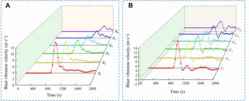
FIGURE 6. Blasting vibration history curves of monitoring points without ground stress, (A) horizontal direction; (B) vertical direction.
It can be observed that as the displacement of the monitoring points increases, the Peak Particle Velocity (PPV) of the blast vibration continuously decreases. Additionally, the occurrence time of the vibration velocity peak at the monitoring points continues to delay, in line with the general pattern of blast-induced vibration in engineering. Furthermore, the vertical blast vibration response at the surrounding rock monitoring points was higher than that in the horizontal direction. The decay pattern of PPV in blasting is generally described in the equation of PPV = K (Q1/3/X)α, which can be simplified to a power function relationship, PPV = KXα (Zhou et al., 2014). The PPV data from monitoring points in both horizontal and vertical directions were fitted, the fitting curves are shown in Figure 7. The correlation coefficients are all greater than 0.98, indicating that the fitting curves accurately represent the PPV decay pattern. The coefficient α characterizes the decay rate of peak particle velocity with distance. The larger the |α|, the faster the decay, compared to the vertical direction, the horizontal direction exhibits a higher decay rate of PPV.
The distribution of tunnel blasting damage under different ground stress conditions is shown in the Figures 8–10.
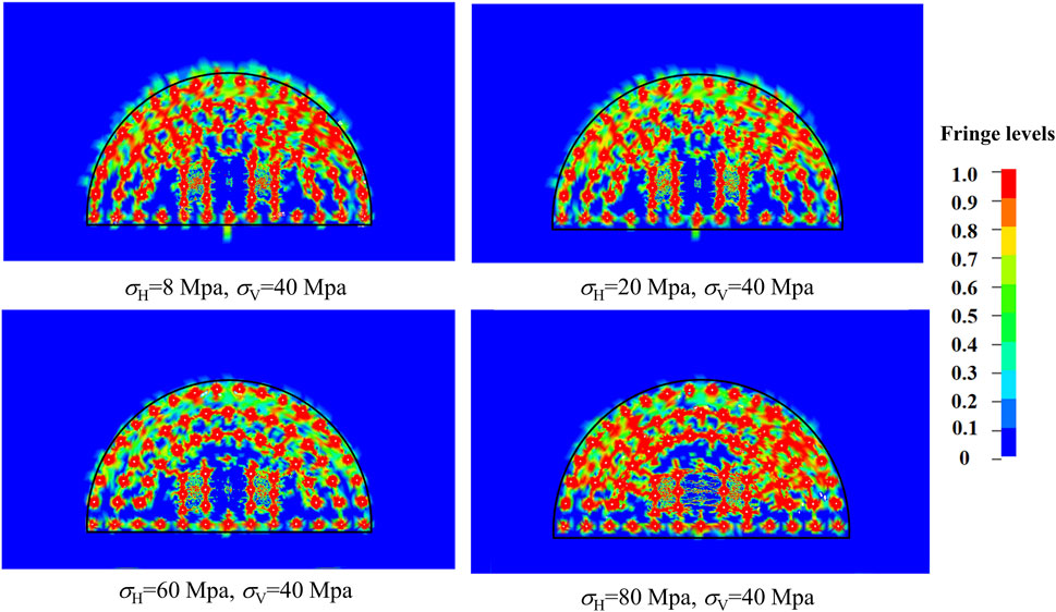
FIGURE 9. Blasting-induced damage of surrounding rock in bidirectional unequal ground stress condition.
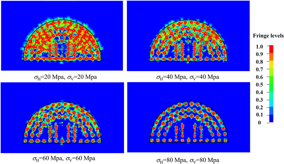
FIGURE 10. Blasting-induced damage of surrounding rock in bidirectional equal ground stress condition.
The compression of confining pressure will further increase the damage in the direction of the maximum principal stress, under unidirectional ground stress conditions, when the ground stress is low. As the ground stress σH increases, the compressive effect of the ground stress will have an inhibition effect on the surrounding rock damage and the cracks in the cutting area. It is found that the increase in ground stress σH has a greater inhibitory effect on the surrounding rock damage compared to the condition of ground stress σV. In bidirectional unequal ground stress conditions, when the lateral pressure coefficient is small, there is over-excavation in the tunnel along the excavation profile, the damage extends in the direction of the maximum principal stress. However, with the increase of the lateral pressure coefficient, the damage zone is distributed more uniformly along the excavation profile. The increase in lateral pressure coefficient, i.e., the increase in ground stress σH, causes the extension of rock fractures in the cutting area along the horizontal direction with higher ground stress. In bidirectional equal ground stress conditions, when the lateral pressure coefficient is 1.0 and the ground stress is low, the damage zone is distributed relatively uniformly along the excavation profile. When the lateral pressure coefficient is 1.0 and the ground stress is high, stress release is limited to a local area. The damage to the surrounding rock along the excavation profile and the extension of cracks in the cutting area are suppressed, and this inhibitory effect is strengthened with the increase of ground stress.
The vertical and horizontal explosion stress data at monitoring points in the computational model were extracted, and scatter plots of stress under different confining pressure conditions were generated and fitted with curves, as shown in Figure 11.
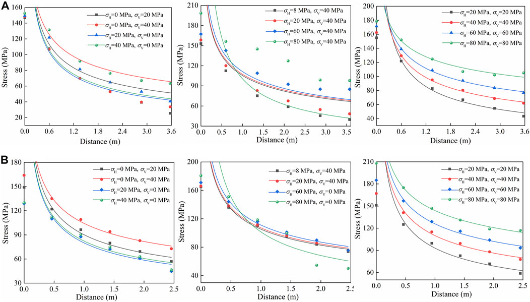
FIGURE 11. Stress attenuation at monitoring points in different directions, (A) horizontal direction; (B) vertical direction.
With the increase of ground stress, the explosion stress wave increases in the direction of maximum principal stress, and the promoting effect is further enhanced under the condition of bidirectional ground stress. The rate of stress attenuation is different under different ground stress conditions, so the distance of explosion stress wave attenuation to damage threshold is different under different ground stress conditions. According to the criterion of rock damage threshold under the action of explosion stress wave in Section 2.2, when the explosion stress wave in the rock decays to the critical stress σci, it is located on the critical fracture surface. Therefore, through the attenuation relationship of explosion stress-displacement in rocks under different ground stress conditions, the distance when the explosion stress decays to the critical stress σci of rocks is obtained, that is, the maximum damage radius, the maximum damage radius under different ground stress conditions is plotted in Figure 12.
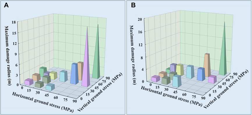
FIGURE 12. Maximum damage radius in different directions, (A) horizontal direction; (B) vertical direction.
The maximum damage radius is closely related to the magnitude of the applied ground stress. Specifically: In unidirectional ground stress conditions, the application of ground stress deepens the damage of surrounding rock in the direction of minimum principal stress, and the damage degree of surrounding rock increases with the increase of unidirectional ground stress. In the condition of bidirectional unequal ground stress, the damage of surrounding rock is inclined to the direction of maximum principal stress. When lateral pressure coefficient is small, the damage of surrounding rock increases with the increase of the lateral pressure coefficient. When lateral pressure coefficient is too large, the damage of surrounding rock in the direction of minimum principal stress is suppressed. In the condition of bidirectional equal ground stress, the maximum damage radius and damage degree of surrounding rock increases with the increase of ground stress, the damage in vertical is more sensitive to the applied ground stress.
Blasting vibration data in the vertical and horizontal directions of the monitoring points of the calculation model were extracted, and the relationship between vibration velocity and distance of monitoring points as shown in Figure 13.
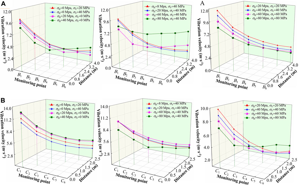
FIGURE 13. PPV attenuation at monitoring points in different directions, (A) horizontal direction; (B) vertical direction.
In the condition of uniaxial ground stress, the dynamic response of vibration velocity in horizontal and vertical directions is related to the direction and magnitude of the ground stress. The vibration velocity of each monitoring point gradually decreases with the increase of ground stresses σH and σV. Taking the vibration velocity of each monitoring point under no ground stress condition as the reference, in conditions No. 1, 2, 3, and 4, the vibration velocity in horizontal decreased by 0.69%, 3.21%, 7.15%, and 16.22%, respectively, while in the vertical decreased by 9.38%, 16.41%, remained unchanged, and increased by 1.56%, respectively. This indicates that under uniaxial ground stress, the vibration velocity in that direction is inhibited, and this inhibition effect is strengthened with the increase of ground stress. In the condition of bidirectional unequal ground stress, with the increase of the lateral pressure coefficient, the vibration velocity in horizontal increases gradually, and the lateral pressure coefficient has no effect on the initial vibration velocity in the vertical direction when σV is less than 60 MPa. When the lateral pressure coefficient is 2, vibration velocity in the horizontal direction decreases and in the vertical direction increases significantly. The vibration velocity in horizontal increases when the bidirectional equal ground stress is low, but the vibration velocity in both directions is suppressed with the increase of the ground stress.
Blasting vibration control has become one of the key factors to reduce blasting damage and ensure smooth engineering. The damage and destruction of retained rock mass caused by blasting is closely related to the strain energy of rock mass under the action of explosion load, and the strain generated in rock mass is proportional to the peak particle velocity. There is a good correlation between the damage of rock mass by blasting and the peak particle velocity, which is also proved by a lot of research and engineering practice. Therefore, PPV is commonly used as a standard for monitoring blasting dynamic effects and controlling blasting safety. The PPV located on the damage boundary under different ground stress conditions was statistically analyzed and drawn in Figure 14.
Taking the PPV threshold of surrounding rock damage without confining pressure as a reference value, the critical PPV threshold in the direction of maximum principal stress under the condition of unidirectional ground stress is larger, and increases compared with the reference value. It is shown that the ground stress enhances the difficulty of rock failure in the direction of maximum principal stress. The PPV threshold of critical damage is smaller than the reference value under the condition of bidirectional unequal ground stress and the lateral pressure coefficient is too small. When the lateral pressure coefficient is too large, the applied ground stress increases the PPV threshold of surrounding rock in the direction of the maximum principal stress, and it is larger than the reference value. Under the condition of bidirectional equal ground stress, with the increase of ground stress, the critical damage PPV threshold of surrounding rock is smaller than the reference value, and the applied bidirectional equal ground stress can inhibit the damage threshold. The general relationship between PPV threshold and ground stress cannot be well expressed by one functional relationship. Unidirectional and bidirectional ground stress conditions are fitted separately, as shown in Figure 15.
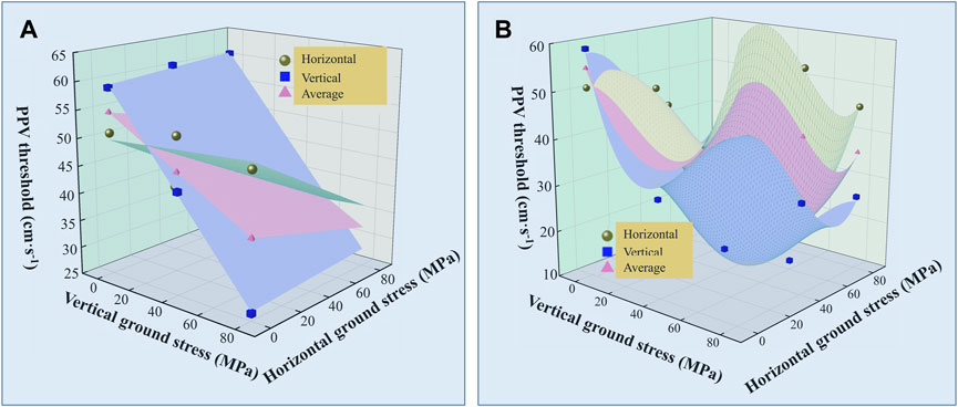
FIGURE 15. Fitting relationship between PPV threshold and ground stress, (A) unidirectional ground stress; (B) bidirectional ground stress.
The PPV thresholds of horizontal and vertical under unidirectional ground stress were fitted respectively, and the function PPV = a0σH + b0σV + c0 was selected. The average value of horizontal and vertical PPV is considered to represent the damage threshold of the whole surrounding rock. Although the fitting relationship of the average value is better, the fitting function verification shows that the theoretical PPV threshold under unidirectional ground stress condition is significantly different from the actual horizontal and vertical thresholds, which does not meet the engineering requirements. In the bidirectional ground stress condition, the function PPV = a1σH3+b1σV3+c1σH2+d1σV2+e1σH + f1σV + g1 was selected. The average theoretical PPV threshold cannot be used to characterize the damage state of the whole surrounding rock, it is necessary to fit separately. The fitting equation can well characterize the general relationship between PPV threshold and ground stress.
In this paper, the finite element calculation model of full section excavation of deep tunnel is established, the dynamic limit tensile strength criterion of rock is introduced, and the damage effect of full section blasting excavation of tunnel surrounding rock is simulated and analyzed. The main conclusions are as follows:
(1) Under unidirectional ground stress condition, with the increase of the ground stress, the compressive effect of the ground stress will produce an inhibition effect on the damage of the surrounding rock and the cracks in the cut area. Under the condition of bidirectional unequal ground stress, the expansion of the damage zone on the excavation contour is inhibited with the increase of the lateral pressure coefficient, and the damage expansion in the direction of the maximum principal stress in the cut area is increased. Under the condition of bidirectional and equal ground stress, when the ground stress is low, the damage zone is evenly distributed along the excavation contour surface. With the increase of ground stress, the stress is only released around the blasthole, and the damage of surrounding rock on the excavation contour surface and the crack expansion in the cut area are inhibited.
(2) Different ground stress conditions result in varying stress propagation characteristics. Under uniaxial ground stress condition, the application of ground stress imposes certain limitations on the rate of stress attenuation. Under the condition of bidirectional equal ground stress, the presence of ground stress has a small amplitude increase on the stress decay rate when the ground stress is low, and has a strong inhibition on the stress decay rate when the ground stress is high. Different stress decay rates affect the damage stress threshold in the rock, resulting in different maximum damage radius when the explosion stress wave decays to the critical stress.
(3) According to the maximum damage radius of rock under different ground stress conditions, the PPV threshold of blasting vibration peak on the damage boundary is calculated. By fitting the general functional relationship between different ground stress and PPV threshold, it is found that the general relationship between damage PPV threshold and ground stress can be well characterized by using linear function under unidirectional ground stress and cubic polynomial function under bidirectional ground stress.
The original contributions presented in the study are included in the article/Supplementary material, further inquiries can be directed to the corresponding author.
QZ: Resources, Supervision, Writing–review and editing. NL: Formal Analysis, Methodology, Writing–original draft. HW: Investigation, Conceptualization, Writing–review and editing. JD: Data curation, Investigation, Writing–original draft.
The author(s) declare financial support was received for the research, authorship, and/or publication of this article. The authors acknowledge the financial support provided by the Natural Science Research Project of Anhui Educational Committee (No. 2023AH051167), the Scientific Research Foundation for High-level Talents of Anhui University of Science and Technology (No. 2022yjrc78).
The authors declare that the research was conducted in the absence of any commercial or financial relationships that could be construed as a potential conflict of interest.
All claims expressed in this article are solely those of the authors and do not necessarily represent those of their affiliated organizations, or those of the publisher, the editors and the reviewers. Any product that may be evaluated in this article, or claim that may be made by its manufacturer, is not guaranteed or endorsed by the publisher.
Chai, S. B., Liu, H., Song, L., Li, X. P., Fu, X. D., and Zhou, Y. Q. (2023). Static pressure and dynamic impact characteristics of filled jointed rock after frozen-thaw cycle damage. Front. Ecol. Evol. 11, 1222676. doi:10.3389/fevo.2023.1222676
Cheng, B., Wang, H. B., Zong, Q., Wang, M. X., Gao, P. F., and Lv, N. (2022). Study on the improved method of wedge cutting blasting with center holes detonated subsequently. Energies 15, 4282. doi:10.3390/en15124282
Cheng, B., Wang, H. B., Zong, Q., Xu, Y., Wang, M. X., and Zheng, Q. Q. (2021). Study of the double wedge cut technique in medium-depth hole blasting of rock roadways. Arab. J. Sci. Eng. 46, 4895–4909. doi:10.1007/s13369-020-05279-8
Fan, Y., Lu, W. B., Yan, P., Chen, M., and Zhang, Y. Z. (2015). Transient characters of energy changes induced by blasting excavation of deep-buried tunnels. Tunn. Undergr. Sp. Tech. 49, 9–17. doi:10.1016/j.tust.2015.04.003
Guan, X. M., Zhang, L., Wang, Y. W., Fu, H. X., and An, J. Y. (2020). Velocity and stress response and damage mechanism of three types pipelines subjected to highway tunnel blasting vibration. Eng. Fail. Anal. 118, 104840. doi:10.1016/j.engfailanal.2020.104840
Hajibagherpour, A. R., Mansouri, H., and Bahaaddini, M. (2020). Numerical modeling of the fractured zones around a blasthole. Comput. Geotech. 123, 103535. doi:10.1016/j.compgeo.2020.103535
Hong, Z. X., Tao, M., Liu, L. L., Zhao, M. S., and Wu, C. Q. (2023). An intelligent approach for predicting overbreak in underground blasting operation based on an optimized XGBoost model. Eng. Appl. Artif. Intell. 126, 107097. doi:10.1016/j.engappai.2023.107097
Huo, X. F., Shi, X. Z., Qiu, X. Y., Zhou, J., Gou, Y. G., Yu, Z., et al. (2020). Rock damage control for large-diameter-hole lateral blasting excavation based on charge structure optimization. Tunn. Undergr. Sp. Tech. 106, 103569. doi:10.1016/j.tust.2020.103569
Ji, L., Zhou, C. B., Lu, S. W., Jiang, N., and Gutierrez, M. (2021a). Numerical studies on the cumulative damage effects and safety criterion of a large cross-section tunnel induced by single and multiple full-scale blasting. Rock Mech. Rock Eng. 54, 6393–6411. doi:10.1007/s00603-021-02630-9
Ji, L., Zhou, C. B., Zhang, B., and Wang, F. X. (2021b). Study on dynamic response and damage effect of surrounding rock in large tunnel under blasting excavation. J. Chin. Railw. Soc. 43, 161–168. doi:10.3969/j.issn.1001-8360.2021.07.021
Li, H., Li, X., Li, J., Xia, X., and Wang, X. (2016). Application of coupled analysis methods for prediction of blast-induced dominant vibration frequency. Earthq. Eng. Eng. Vib. 15, 153–162. doi:10.1007/s11803-016-0312-6
Liu, D., Lu, W. B., Yang, J. H., Gao, J. L., Yan, P., Hu, S. T., et al. (2022). Relationship between cracked-zone radius and dominant frequency of vibration in tunnel blasting. Int. J. Rock Mech. Min. Sci. 160, 105249. doi:10.1016/j.ijrmms.2022.105249
Lu, W. B., Yang, J. H., Yan, P., Chen, M., Zhou, C. B., Luo, Y., et al. (2012). Dynamic response of rock mass induced by the transient release of in-situ stress. Int. J. Rock Mech. Min. Sci. 53, 129–141. doi:10.1016/j.ijrmms.2012.05.001
Lv, A. Z., Liu, Y. J., and Yin, C. L. (2021). Extension failure criterion for intact rock under tension and compression. Chin. J. Theor. Appl. 53, 1647–1657. doi:10.6052/0459-1879-21-026
Mahmoodzadeh, A., Nejati, H. R., Mohammadi, M., Mohammed, A. S., Ibrahim, H. H., and Rashidi, S. (2022). Numerical and Machine learning modeling of hard rock failure induced by structural planes around deep tunnels. Eng. Fract. Mech. 271, 108648. doi:10.1016/j.engfracmech.2022.108648
Pan, C., Zhao, G. M., Meng, X. R., Dong, C. L., and Gao, P. F. (2023). Numerical investigation of the influence of mineral mesostructure on quasi-static compressive behaviors of granite using a breakable grain-based model. Front. Ecol. Evol. 11. doi:10.3389/fevo.2023.1288870
Sazid, M., and Singh, T. N. (2013). Two-dimensional dynamic finite element simulation of rock blasting. Arab. J. Geosci. 6, 3703–3708. doi:10.1007/s12517-012-0632-4
Simha, K. R. Y., Fourney, W. L., Barker, D. B., and Shukla, A. (1983). “Model studies on explosively driven cracks under confining in-situ stresses,” in Proc. 1st int. symp. on rock frag. by blasting (Sweden: Luleå).
Uysal, Ö., Arpaz, E., and Berber, M. (2007). Studies on the effect of burden width on blast-induced vibration in open-pit mines. Environ. Geol. 53, 643–650. doi:10.1007/s00254-007-0679-9
Wang, H. C., Wang, Z. L., Wang, J. G., Wang, S. M., Wang, H. R., Yin, Y. G., et al. (2021). Effect of confining pressure on damage accumulation of rock under repeated blast loading. Int. J. Impact Eng. 156, 103961. doi:10.1016/j.ijimpeng.2021.103961
Wu, X. D., Gong, M., Wu, H. J., Hu, G. F., and Wang, S. J. (2023). Vibration reduction technology and the mechanisms of surrounding rock damage from blasting in neighborhood tunnels with small clearance. Int. J. Min. Sci. Techno. 33, 625–637. doi:10.1016/j.ijmst.2022.10.009
Xie, L. X., Lu, W. B., Zhang, Q. B., Jiang, Q. H., Chen, M., and Zhao, J. (2017). Analysis of damage mechanisms and optimization of cut blasting design under high in situ stresses. Tunn. Undergr. Sp. Tech. 66, 19–33. doi:10.1016/j.tust.2017.03.009
Xu, Y., Tang, J. X., Yu, Y. C., Yao, W., Wu, B. B., and Xia, K. W. (2023). Dynamic responses and failure mechanisms of the existing tunnel under transient excavation unloading of an adjacent tunnel. J. Rock Mech. Geotech. Eng. 15, 2930–2942. doi:10.1016/j.jrmge.2023.03.014
Yang, J. H., Lu, W. B., Jiang, Q. H., Yao, C., and Zhou, C. B. (2016). Frequency comparison of blast-induced vibration per delay for the full-face millisecond delay blasting in underground opening excavation. Tunn. Undergr. Sp. Tech. 51, 189–201. doi:10.1016/j.tust.2015.10.036
Yi, C. P., Sjöberg, J., and Johansson, D. (2017). Numerical modelling for blast-induced fragmentation in sublevel caving mines. Tunn. Undergr. Sp. Tech. 68, 167–173. doi:10.1016/j.tust.2017.05.030
Yilmaz, O., and Unlu, T. (2013). Three dimensional numerical rock damage analysis under blasting load. Tunn. Undergr. Sp. Tech. 38, 266–278. doi:10.1016/j.tust.2013.07.007
Zheng, Q. Q., Qian, J. W., Zhang, H. J., Chen, Y. K., and Zhang, S. H. (2024). Velocity tomography of cross-sectional damage evolution along rock longitudinal direction under uniaxial loading. Tunn. Undergr. Sp. Tech. 143, 105503. doi:10.1016/j.tust.2023.105503
Zhou, J. R., Lu, W. B., Zhang, L., Chen, M., and Yan, P. (2014). Attenuation of vibration frequency during propagation of blasting seismic wave. Chin. J. Rock Mech. Eng. 33, 2171–2178. doi:10.13722/j.cnki.jrme.2014.11.002
Keywords: surrounding rock, blasting, ground stress, numerical simulation, peak particle velocity
Citation: Zong Q, Lv N, Wang H and Duan J (2024) Numerical analysis on dynamic response and damage threshold characterization of deep rock mass under blasting excavation. Front. Mater. 11:1329549. doi: 10.3389/fmats.2024.1329549
Received: 02 November 2023; Accepted: 11 January 2024;
Published: 26 January 2024.
Edited by:
Kai Liu, University of Oxford, United KingdomReviewed by:
Chenglong He, North University of China, ChinaCopyright © 2024 Zong, Lv, Wang and Duan. This is an open-access article distributed under the terms of the Creative Commons Attribution License (CC BY). The use, distribution or reproduction in other forums is permitted, provided the original author(s) and the copyright owner(s) are credited and that the original publication in this journal is cited, in accordance with accepted academic practice. No use, distribution or reproduction is permitted which does not comply with these terms.
*Correspondence: Nao Lv, MjAyMjA0NkBhdXN0LmVkdS5jbg==
Disclaimer: All claims expressed in this article are solely those of the authors and do not necessarily represent those of their affiliated organizations, or those of the publisher, the editors and the reviewers. Any product that may be evaluated in this article or claim that may be made by its manufacturer is not guaranteed or endorsed by the publisher.
Research integrity at Frontiers

Learn more about the work of our research integrity team to safeguard the quality of each article we publish.